change time SKODA SUPERB 2014 2.G / (B6/3T) Owner's Guide
[x] Cancel search | Manufacturer: SKODA, Model Year: 2014, Model line: SUPERB, Model: SKODA SUPERB 2014 2.G / (B6/3T)Pages: 246, PDF Size: 17.16 MB
Page 187 of 246
CAUTION■Under no circumstances must radiator antifreeze or other additives be added
to the windscreen washer fluid.■
If the vehicle is fitted with a headlight cleaning system, only cleaning prod-
ucts which do not attack the polycarbonate coating of the headlights must be
added to the windscreen washer fluid.
■
Do not remove the filter from the windscreen washer fluid reservoir when re-
filling, as this may cause contamination of the liquid transportation system,
leading in turn to a windscreen washer system malfunction.
Engine oil
Introduction
This chapter contains information on the following subjects:
Specifications and capacity
185
Checking the oil level
186
Replenishing
187
Changing
187
The engine has been factory-filled with a high-grade oil that can be use
throughout the year - except in extreme climate zones.
The engine oils are undergoing continuous further development. Thus the in- formation stated in this Owner's Manual is only correct at the time of publica-
tion.
ŠKODA Service Partners are informed about the latest changes by the manu-
facturer. We therefore recommend that the oil change be completed by a
ŠKODA Service Partner.
The specifications (VW standards) stated in the following can be indicated sep-
arately or together with other specifications on the bottle.
The oil capacities include oil filter change. Check the oil level when filling; do
not over fill. The oil level must be between the markings » page 186.
WARNING■
The engine compartment of your car is a hazardous area. The following
warning instructions must be followed at all times when working in the en-
gine compartment » page 182.■
Do not continue your journey if for some reason it is not possible to top
up the engine oil
. Switch off the engine and seek assistance from a spe-
cialist garage.
■
Do not drive on if the oil level is above range
A
» Fig. 163 on page 186
. Switch off the engine and seek assistance from a specialist garage.
CAUTION
Do not pour any additives into the engine oil – risk of serious damage to the
engine parts!
Note
■ Before a long drive we recommend that you purchase and carry with you en-
gine oil which complies with the specification for your vehicle.■
We recommend that you use oils from ŠKODA Original Accessories.
■
If your skin has come into contact with oil, it must be washed thoroughly.
Specifications and capacity
Read and observe
and on page 185 first.
Specifications and capacity (in l) for vehicles with flexible service intervals
Petrol enginesSpecificationCapacity1.4 ltr./92 kW TSIVW 503 00, VW 504 003.61.8 l/112, 118 kW TSIVW 504 004.62.0 ltr./147 kW TSIVW 504 004.63.6 l/191 kW FSIVW 504 005.5Diesel engines a)SpecificationCapacity1.6 ltr./77 kW TDI CRVW 507 004.32.0 ltr/103 kW TDI CR DPFVW 507 004.32.0 ltr/125 kW TDI CR DPFVW 507 004.3a)
Engine oil VW 505 01 can optionally be used in diesel engines
without a DPF.
185Inspecting and replenishing
Page 188 of 246
Specifications and capacity (in l) for vehicles with fixed service intervalsPetrol enginesSpecificationCapacity1.4 ltr./92 kW TSIVW 501 01, VW 502 003.6
1.8 l/112, 118 kW TSI
VW 502 00
4.6
applies to RussiaSAE 0W - 30
VW 502 00/505 00
2.0 ltr./147 kW TSI
VW 502 00
4.6
applies to Russia SAE 0W - 30
VW 502 00/505 003.6 l/191 kW FSIVW 502 005.5Diesel engines a)SpecificationCapacity1.6 ltr./77 kW TDI CRVW 507 004.32.0 ltr/103 kW TDI CR DPFVW 507 004.32.0 ltr/125 kW TDI CR DPFVW 507 004.3a)
Engine oil VW 505 01 can optionally be used in diesel engines
without a DPF.
CAUTION
■
If the above engine oils are not available, a different engine oil can be used in
an emergency. To prevent damage to the engine, a maximum of 0.5 litres only
of the following engine oils may be used until the next oil change: ■ For petrol engine models: ACEA A3/ACEA B4 or API SN/API SM;
■ For diesel engine models: ACEA C3 or API CJ-4.
Checking the oil level
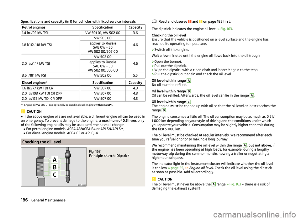
Fig. 163
Principle sketch: Dipstick
Read and observe and on page 185 first.
The dipstick indicates the engine oil level » Fig. 163.
Checking the oil level
Ensure that the vehicle is positioned on a level surface and the engine has
reached its operating temperature.
›
Switch off the engine.
Wait a few minutes until the engine oil flows back into the oil trough.
›
Open the bonnet.
›
Pull out the dipstick.
›
Wipe the dipstick with a clean cloth and insert it again to the stop.
›
Pull the dipstick out again and check the oil level.
Oil level within range
A
No oil must be refilled.
Oil level within range
B
Oil can be refilled. Afterwards, the oil level can lie in the range
A
.
Oil level within range
C
The engine must be topped up with oil so that the oil level at least reaches the
range
B
.
The engine consumes a little oil. The oil consumption may be as much as 0.5 l/
1 000 km depending on your style of driving and the conditions under which
you operate your vehicle. Consumption may be slightly higher than this during
the first 5 000 km.
The oil level must be checked at regular intervals. We recommend after each
time you refuel or prior to making a long journey.
We recommend maintaining the oil level within the range
A
, but not above , if
the engine has been operating at high loads, for example, during a lengthy
motorway trip during the summer months, towing a trailer or negotiating a
high mountain pass.
The indicator light in the instrument cluster will indicate whether the oil level
is too low » page 35,
Engine oil level
. Check the oil level using the dipstick
as soon as possible. Add oil accordingly.
CAUTION
The oil level must never be above the A range » Fig. 163 – there is a risk of
damaging the exhaust system!186General Maintenance
Page 189 of 246
ReplenishingRead and observe
and on page 185 first.
›
Check the oil level » page 186.
›
Unscrew the cap of the engine oil filler opening » Fig. 161 on page 184 .
›
Replenish the oil in portions of 0.5 litres in accordance with the correct speci-
fications » page 185 .
›
Check the oil level » page 186.
›
Carefully screw on the oil filler opening cap and push the dipstick in fully.
Changing
Read and observe
and on page 185 first.
The engine oil must be changed according to prescribed service intervals or ac-
cording to the service interval display » Service plan .
Coolant
Introduction
This chapter contains information on the following subjects:
Capacity
188
Checking the coolant level
188
Replenishing
188
The coolant consists of water with coolant additive. This mixture guarantees
antifreeze protection, protects the cooling/heater system against corrosion
and prevents lime formation.
Vehicles exported to countries with a mild climate are already factory-filled
with a coolant which offers antifreeze protection down to about -25 ℃. In
these countries, the concentration of coolant additive should be at least 40%.
Vehicles exported to countries with a cold climate are already factory-filled
with a coolant which offers antifreeze protection down to about -35 °C. In
these countries, the concentration of coolant additive should be at least 50%.
If a higher concentration of antifreeze is required for climatic reasons, the con-
centration of coolant additive can be increased up to a maximum of 60% (anti-
freeze protection down to approx. -40 °C).
When refilling, only use the same antifreeze identified on the coolant expan-
sion vessel » Fig. 164 on page 188 .WARNING■
The engine compartment of your car is a hazardous area. The following
warning instructions must be followed at all times when working in the en-
gine compartment » page 182.■
Do not continue your journey if for some reason it is not possible to fill
with coolant under the current circumstances
. Switch off the engine and
seek assistance from a specialist garage.
CAUTION
■ The concentration of coolant additive in the coolant must never be under
40%.■
Over 60% of coolant additive in the coolant reduces the antifreeze protec-
tion and cooling effect.
■
A coolant additive that does not comply with the correct specifications can
significantly reduce the corrosion protection.
■
Any faults resulting from corrosion may cause a loss of coolant and can con-
sequently result in major engine damage!
■
Do not fill the coolant above the mark
A
» Fig. 164 on page 188 .
■
If a fault causes the engine to overheat, we recommend visiting a specialist
garage, as otherwise serious engine damage may occur.
■
Additional headlights and other attached components in front of the air inlet
impair the cooling efficiency of the coolant.
■
Never cover the radiator - there is a risk of the engine overheating.
187Inspecting and replenishing
Page 191 of 246
Brake fluid
Introduction
This chapter contains information on the following subjects:
Checking the brake fluid level
189
Changing
189WARNING■ The engine compartment of your car is a hazardous area. The following
warning instructions must be followed at all times when working in the en-
gine compartment » page 182.■
Do not continue your journey if the fluid level has fallen below the MIN
marking » Fig. 165 on page 189 ,
- there is a risk of an accident. Seek help
from a specialist garage.
■
Do not use used brake fluid - the function of the brake system may be im-
paired – risk of accident!
CAUTION
Brake fluid damages the paintwork of the vehicle.
Note
■ The brake fluid is changed as part of a compulsory inspection service.■We recommend using brake fluids from the ŠKODA Original Accessories
range.
Checking the brake fluid level
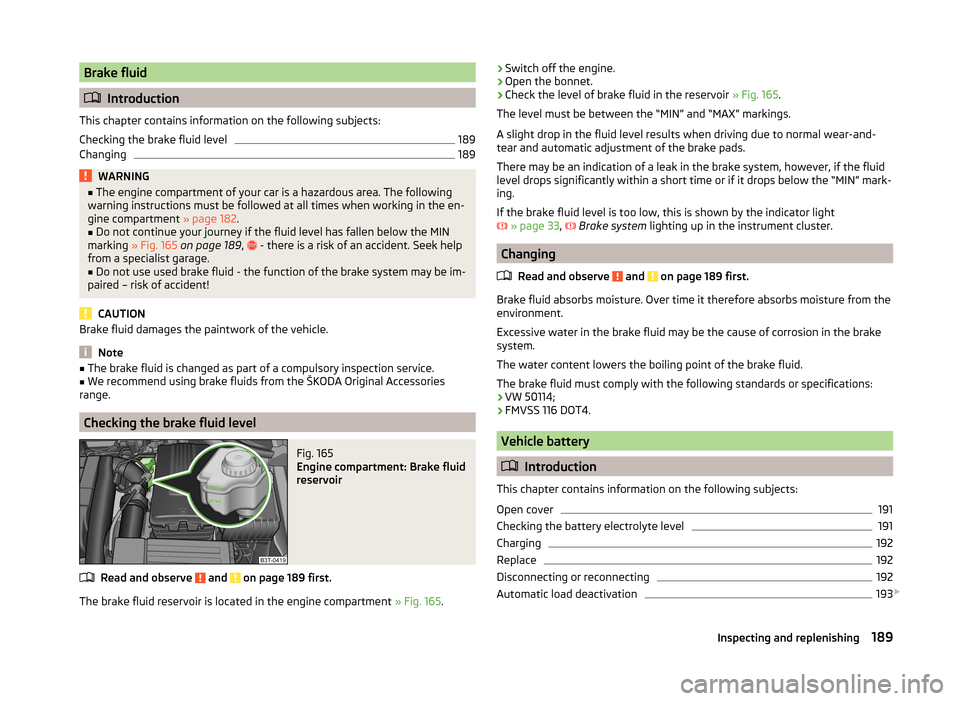
Fig. 165
Engine compartment: Brake fluid
reservoir
Read and observe and on page 189 first.
The brake fluid reservoir is located in the engine compartment » Fig. 165.
›Switch off the engine.›Open the bonnet.›
Check the level of brake fluid in the reservoir
» Fig. 165.
The level must be between the “MIN” and “MAX” markings.
A slight drop in the fluid level results when driving due to normal wear-and-
tear and automatic adjustment of the brake pads.
There may be an indication of a leak in the brake system, however, if the fluid
level drops significantly within a short time or if it drops below the “MIN” mark-
ing.
If the brake fluid level is too low, this is shown by the indicator light
» page 33 ,
Brake system
lighting up in the instrument cluster.
Changing
Read and observe
and on page 189 first.
Brake fluid absorbs moisture. Over time it therefore absorbs moisture from the
environment.
Excessive water in the brake fluid may be the cause of corrosion in the brake
system.
The water content lowers the boiling point of the brake fluid.
The brake fluid must comply with the following standards or specifications: › VW 50114;
› FMVSS 116 DOT4.
Vehicle battery
Introduction
This chapter contains information on the following subjects:
Open cover
191
Checking the battery electrolyte level
191
Charging
192
Replace
192
Disconnecting or reconnecting
192
Automatic load deactivation
193
189Inspecting and replenishing
Page 193 of 246
■Do not place the battery in direct daylight in order to protect the vehicle bat-
tery housing from the effects of ultra-violet light.■
If the vehicle has not been driven for more than 3 to 4 weeks, the battery will
discharge. This is because certain electrical components consume electricity
(e. g. control units) also in idle state. Prevent the battery from discharging by
disconnecting the battery's negative terminal (-) or continuously charging the
battery with a very low charging current.
■
If the vehicle is frequently used for making short trips, the vehicle battery
will not have time to charge up sufficiently and may discharge.
For the sake of the environment
A vehicle battery that has been removed is a special type of hazardous waste.
These must be disposed of in accordance with national legal regulations.
Note
You should replace batteries older than 5 years.
Open cover
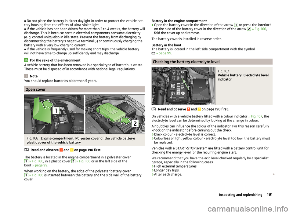
Fig. 166
Engine compartment: Polyester cover of the vehicle battery/
plastic cover of the vehicle battery
Read and observe
and on page 190 first.
The battery is located in the engine compartment in a polyester cover
1
» Fig. 166 , in a plastic cover
2
» Fig. 166 or in the left side of the
boot » page 99 .
When working on the battery, the edge of the polyester battery cover
1
» Fig. 166 is inserted between the battery and the side wall of the battery
cover.
Battery in the engine compartment›Open the battery cover in the direction of the arrow 1 or press the interlock
on the side of the battery cover in the direction of the arrow 2
» Fig. 166 ,
fold the cover up and remove.
The battery cover is installed in reverse order.
Battery in the boot
The battery is located in the left side compartment with the symbol
» page 99 .
Checking the battery electrolyte level
Fig. 167
Vehicle battery: Electrolyte level
indicator
Read and observe and on page 190 first.
On vehicles with a vehicle battery fitted with a colour indicator » Fig. 167, the
electrolyte level can be determined by looking at the change in colour.
Air bubbles can influence the colour of the indicator. For this reason carefully knock on the indicator before carrying out the check.
› Black colour - electrolyte level is correct.
› Colourless or light yellow colour - electrolyte level too low, the battery must
be replaced.
Vehicles with a START-STOP system are fitted with a battery control unit for
checking the energy level for the recurring engine start.
We recommend that you have the acid level checked regularly by a specialist
garage, especially in the following cases.
› High external temperatures.
› Longer day trips.
› After each charge.
191Inspecting and replenishing
Page 221 of 246
No.Consumer11Auxiliary heating and ventilation control unit12Data bus control unit13Engine control unit14Ignition15Lambda probe (petrol engine), glow plug system relay and fuel
pump (diesel engine)16Front right main headlight, right tail light17Horn18Audio amplifier (sound system)19Windscreen wipers20Valve for metering fuel, coolant pump, high pressure pump21Lambda probe22Clutch pedal switch23Coil of the coolant pump relay valves, high-pressure pump24Radiator fan25Pump for ABS26Front left main headlight, left tail light27Control unit for glow plug system28Windscreen heater29Power to the internal fuse carrier30Power supply for terminal 15 (ignition on)a)
In order not to drain the battery unnecessarily when starting the engine, the electrical components of
this terminal are automatically switched off.
Bulbs
Introduction
This chapter contains information on the following subjects:
Headlights
220
Replacing the low beam bulb
220
Replacing bulb for main beam and daytime running lights
220
Replacing bulb for main beam
221
Replacing the bulb for the fog light
221Replacing the bulb for the licence plate light222Rear light (Superb Combi)222
Replacing bulbs in rear light (Superb Combi)
223
Some manual skills are required to change a bulb. For this reason, we recom-
mend having bulbs replaced by a specialist garage or seeking other expert help
in the event of any uncertainties.
› Switch off the ignition and all of the lights before replacing a bulb.
› Faulty bulbs must only be replaced with the same type of bulbs. The designa-
tion is located on the light socket or the glass bulb.
› A stowage compartment for replacement bulbs is located in a plastic box in
the spare wheel or underneath the floor covering in the boot.
WARNING■ Always read and observe the warnings before completing any work in the
engine compartment » page 182.■
Accidents can be caused if the road in front of the vehicle is not suffi-
ciently illuminated and the vehicle cannot or can only be seen with difficul-
ty by other road users.
■
Bulbs H7 H8 and H15 are pressurised and may burst when changing the
bulb - risk of injury! We therefore recommended wearing gloves and safety
glasses when changing a bulb.
■
Gas discharge bulbs (xenon bulbs) operate with a high voltage, professio-
nal knowledge is required – risk of death!
■
Switch off the respective vehicle light when changing the bulb.
CAUTION
Do not take hold of the glass bulb with naked fingers (even the smallest
amount of dirt reduces the working life of the light bulb). Use a clean cloth,
napkin, or similar.
Note
■ This Owner's Manual only describes the replacement of bulbs where it is pos-
sible to replace the bulbs on your own without any complications arising. Other
bulbs must be replaced by a specialist garage.■
We recommend that a box of replacement bulbs always be carried in the ve-
hicle. Replacement bulbs can be purchased from ŠKODAOriginal Accessories.
■
We recommend having the headlight settings checked by a specialist garage
after replacing a bulb in the main, low or fog beam.
■
In case of failure of a xenon gas discharge lamp or an LED diode, visit a spe-
cialist garage.
219Fuses and light bulbs
Page 222 of 246
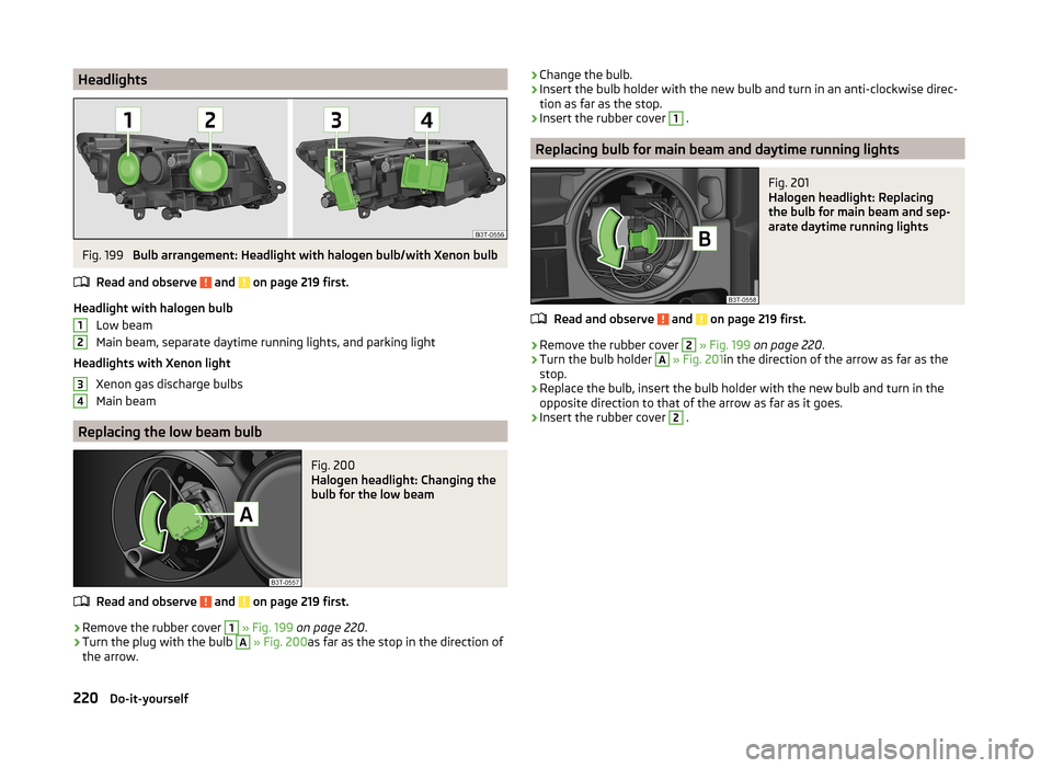
HeadlightsFig. 199
Bulb arrangement: Headlight with halogen bulb/with Xenon bulb
Read and observe
and on page 219 first.
Headlight with halogen bulb Low beam
Main beam, separate daytime running lights, and parking light
Headlights with Xenon light Xenon gas discharge bulbs
Main beam
Replacing the low beam bulb
Fig. 200
Halogen headlight: Changing the
bulb for the low beam
Read and observe and on page 219 first.
›
Remove the rubber cover
1
» Fig. 199 on page 220 .
›
Turn the plug with the bulb
A
» Fig. 200 as far as the stop in the direction of
the arrow.
1234› Change the bulb.›Insert the bulb holder with the new bulb and turn in an anti-clockwise direc-
tion as far as the stop.›
Insert the rubber cover
1
.
Replacing bulb for main beam and daytime running lights
Fig. 201
Halogen headlight: Replacing
the bulb for main beam and sep-
arate daytime running lights
Read and observe and on page 219 first.
›
Remove the rubber cover
2
» Fig. 199 on page 220 .
›
Turn the bulb holder
A
» Fig. 201 in the direction of the arrow as far as the
stop.
›
Replace the bulb, insert the bulb holder with the new bulb and turn in the
opposite direction to that of the arrow as far as it goes.
›
Insert the rubber cover
2
.
220Do-it-yourself
Page 236 of 246
Temperature gauge29
Warning light34
CORNER See Fog lights with CORNER function
69
Correct seated position7
Driver7
Front passenger8
Instructions9
Rear seats9
Counter for distance driven30
Cruise control system Activating/deactivating
158
Changing the stored speed159
Storing and maintaining speed159
Switching off temporarily159
Warning light39
Cruise Control System158
Cup holders88
D
DAY LIGHT see Daylight running lights
67
Daylight running lights67
De-icing the windscreen and rear window73
Deactivating an airbag19
Decorative films175
Delayed locking of the boot lid see boot lid
56
Diesel refer to Fuel
181
diesel - particulate filter
37
Diesel fuel Operation in winter
181
Diesel particulate filter warning light
37
Digital Clock Time
30
Dipstick186
Display29
Compass points46
Coolant temperature29
Fuel supply30
Gear changes40
Service intervals46
Display a low temperature40
Display of the second speed31
Distance driven30
Door Child safety lock
53
Closing53
Emergency locking the driver's door212
Opening53
Warning light door open34
Door locking Emergency
212
Door open Warning light
34
Doors Emergency locking
212
Driver Steering Recommendation (DSR)152
Driving Abroad
150
Driving through water on streets149
Emissions225
Fuel consumption225
Driving economically Economical gear changing
146
Driving through water149
DSR152
DVD-preinstallation134
E
Economical and environmentally friendly driv- ing
146
Economical driving Ballast
147
Driving at full throttle147
Idling147
Looking ahead146
Regular maintenance148
Saving energy148
Short distances147
Tyre inflation pressure147
EDL Operation
152
Electrical power windows61
Button in the driver's door59, 60
Button in the rear doors61
Operational faults62
Electric boot lid Force limit
57
Manual operation57
Electric luggage compartment lid Acoustic signals
59
Adjusting the top lid position59
Deleting the top lid position59
Malfunctions59
Operating57
Electric sliding/tilting roof62
Electronic Differential Lock (EDL)152
Electronic immobilizer136
Electronic Stability Control (ESC)151
Emergency Activation of the sliding/tilting roof
214
Changing a wheel201
Door locking212
Hazard warning light system70
jump-starting207
Jump-starting207
Locking the driver's door212
Selector lever-unlocking213
Sliding/tilting roof213
Start engine - KESSY139
Switching off the ignition –KESSY140
Towing the using the tow hitch210
Towing the vehicle208
Tyre repair204
234Index
Page 244 of 246
ŠKODA AUTO a.s. pursues a policy of constant product and model develop-
ment. We trust that you will understand that changes to models in terms of
shape, equipment and engineering, may be introduced at any time. The infor-
mation about appearance, performances, dimensions, weight, standards and
functions of the vehicle is correct at the time of publication. Some equipment
might only be introduced at a later date, or might only be offered in certain
markets; information is provided by ŠKODA Partners. It is therefore not possi-
ble for legal claims to be made based on the data, illustrations and descrip-
tions contained in this Owner's Manual.Reprinting, reproduction, translation, or any other use, either in whole or in
part, is not permitted without the written consent of ŠKODA AUTO a.s..
ŠKODA AUTO a.s. expressly reserves all rights relating to copyright laws.
Subject to change.
Issued by: ŠKODA AUTO a.s.
© ŠKODA AUTO a.s. 2014