key SKODA SUPERB 2014 2.G / (B6/3T) Workshop Manual
[x] Cancel search | Manufacturer: SKODA, Model Year: 2014, Model line: SUPERB, Model: SKODA SUPERB 2014 2.G / (B6/3T)Pages: 246, PDF Size: 17.16 MB
Page 170 of 246
Note■After coupling the trailer and connecting the power socket, check that the
rear lights on the trailer are working correctly.■
If there is an error in the trailer lighting, check the fuses in the fuse box in
the dash panel » page 216.
■
Contact between the breakaway cable and the safety eyelet can result in
mechanical wear on the surface protection of the eyelet. Such wear does not
impair the functioning of the safety eyelet and does not constitute a fault. It is
excluded from the warranty coverage.
■
If you tow a trailer frequently, you should also have your vehicle inspected
between service intervals.
■
The handbrake on the towing vehicle must be applied when coupling and un-
coupling the trailer.
Trailer stabilisation (TSA)
Read and observe
on page 166 first.
The trailer stabilisation is an extension of the stabilisation control that works
in conjunction with the counter-steering assistance to reduce the amount the
trailer "sways".
After turning on the ignition, the ESC indicator light in the instrument clus-
ter lights up for about 2 seconds longer than the ABS indicator light.
Function requirements for trailer stabilisation. The coupling device was factory-fitted or purchased from the ŠKODA Origi-
nal Accessories.
The ESC is active. (Warning lights or
do
not illuminate in the instru-
ment cluster).
The trailer is electrically connected to the towing vehicle via the trailer
socket.
The speed is higher than approx. 60 km/h.
The trailer has a rigid drawbar.
WARNINGThe increased safety offered by the trailer stabilisation must not tempt you to take greater risks than otherwise.CAUTION■ The trailer stabilisation need not be able to correctly detect all of driving sit-
uations.■
Light trailers that sway are not always detected and therefore stabilised ac-
cordingly by the trailer stabilisation.
■
Release the pressure on the accelerator pedal if the system is being regula-
ted.
■
Avoid abrupt and sudden driving/braking manoeuvres.
Note
The trailer stabilisation works for both braked and unbraked trailers.
Anti-theft alarm system
Read and observe
on page 166 first.
When the vehicle is locked, the alarm is activated when the electrical connec-
tion to the trailer is interrupted.
Always switch off the anti-theft alarm system before a trailer is coupled or un-
coupled » page 54 .
Conditions for including a trailer in the anti-theft alarm system. The vehicle is factory-fitted with an anti-theft alarm system and towing
device.
The trailer is electrically connected to the towing vehicle via the trailer
socket.
The electrical system of the vehicle and trailer is functional.
The vehicle is locked with the vehicle key and the anti-theft alarm system
is activated.
Note
For technical reasons, trailers with rear LED lights cannot be connected to the
anti-theft alarm system.168Driving
Page 184 of 246
CAUTION■Just filling the tank once with diesel fuel that does not comply with the
standard, can cause severe damage to parts of the engine, the fuel and ex-
haust system!■
If a different fuel other than diesel fuel, which complies to the above men-
tioned standards (e.g. petrol) is used by mistake do not start the engine or
switch on the ignition! Extensive damage to engine parts can occur! We rec-
ommend that you have the fuel system cleaned by a specialist garage.
■
Water which has collected in the fuel filter can cause engine faults.
CAUTION
■ The vehicle cannot be operated with bio fuel RME, therefore this fuel must
not be filled in the tank and used for driving the vehicle. The use of biofuel
RME can cause considerable damage to parts of the engine or fuel system.■
Do not mix any fuel additives, so-called “flow improvers” (petrol and similar
agents), into the diesel. This can result in considerable damage to parts of the
engine or the exhaust system!
Engine compartment
Introduction
This chapter contains information on the following subjects:
Opening and closing the bonnet
183
Engine compartment overview
184
Radiator fan
184
Windscreen washer system
184WARNINGInjuries or scolding or risks of accident or fire may occur when working in
the engine compartment. For this reason, it is essential to comply with the
warning instructions outlined below and with the general applicable safety
rules. The engine compartment of your car is a hazardous area!WARNINGInstructions before beginning work in the engine compartment■Turn off the engine and withdraw the ignition key.■
Firmly apply the handbrake.
WARNING (Continued)■ If the vehicle is fitted with a manual gearbox, move the gearshift lever in-
to Neutral, or if the vehicle is fitted with an automatic gearbox, move the
selector lever into position P.■
Allow the engine to cool.
■
Never open the bonnet if you can see steam or coolant escaping from the
engine compartment – risk of scalding! Wait until no more steam or coolant
is escaping.
WARNINGInformation for working in the engine compartment■Keep all people, especially children, away from the engine compartment.■
Never touch the radiator fan while the engine is still warm. The fan might
suddenly start running!
■
Do not touch any hot engine parts – risk of burns!
■
The coolant is harmful to health.
■
Avoid contact with the coolant.
■
Coolant vapours are harmful to health.
■
Never open the end cover of the coolant expansion reservoir while the
engine is still warm. The cooling system is pressurized!
■
When opening the end cover of the coolant expansion reservoir, cover it
with a cloth to protect your face, hands and arms from hot steam or hot
coolant.
■
If any coolant splashes into your eyes, immediately rinse out your eyes
with clear water and contact a doctor as soon as possible.
■
Always keep the coolant in the original container, safe from people who
are not completely independent, especially children - there is a danger of
poisoning!
■
If coolant is swallowed, consult a doctor immediately.
■
Never spill fluids on the hot engine. Such fluids (e.g. the antifreeze con-
tained in the coolant) may ignite!
WARNINGInformation for working in the engine compartment with the engine run-
ning■
Pay particular attention to rotating engine parts (e.g. V-ribbed belt, gen-
erator, radiator fan) and the high-voltage ignition system – risk to life!
■
Never touch the electric wiring on the ignition system.
182General Maintenance
Page 203 of 246
The fire extinguisher must be checked by an authorised person once a year.
The national legal requirements must be observed.WARNINGThe fire extinguisher must always be secured safely so that they do not
come loose when making an emergency braking or in a vehicle collision
which could cause injuries to occupants.
Note
■ The fire extinguisher must comply with national legal requirements.■Pay attention to the expiration date of the fire extinguisher. Proper function-
ing of the fire extinguisher is not assured once it has passed its expiry date.■
The fire extinguisher is part of the scope of delivery in certain countries only.
Vehicle tool kit
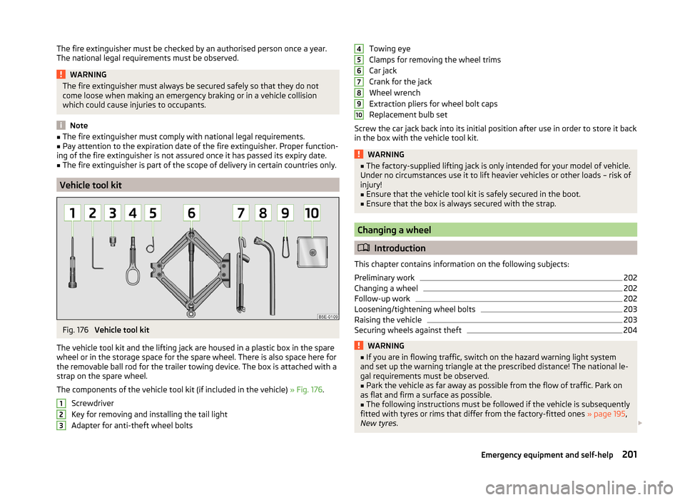
Fig. 176
Vehicle tool kit
The vehicle tool kit and the lifting jack are housed in a plastic box in the spare
wheel or in the storage space for the spare wheel. There is also space here for
the removable ball rod for the trailer towing device. The box is attached with a
strap on the spare wheel.
The components of the vehicle tool kit (if included in the vehicle) » Fig. 176.
Screwdriver
Key for removing and installing the tail light
Adapter for anti-theft wheel bolts
123Towing eye
Clamps for removing the wheel trims
Car jack
Crank for the jack
Wheel wrench
Extraction pliers for wheel bolt caps
Replacement bulb set
Screw the car jack back into its initial position after use in order to store it back
in the box with the vehicle tool kit.WARNING■ The factory-supplied lifting jack is only intended for your model of vehicle.
Under no circumstances use it to lift heavier vehicles or other loads – risk of
injury!■
Ensure that the vehicle tool kit is safely secured in the boot.
■
Ensure that the box is always secured with the strap.
Changing a wheel
Introduction
This chapter contains information on the following subjects:
Preliminary work
202
Changing a wheel
202
Follow-up work
202
Loosening/tightening wheel bolts
203
Raising the vehicle
203
Securing wheels against theft
204WARNING■ If you are in flowing traffic, switch on the hazard warning light system
and set up the warning triangle at the prescribed distance! The national le-
gal requirements must be observed.■
Park the vehicle as far away as possible from the flow of traffic. Park on
as flat and firm a surface as possible.
■
The following instructions must be followed if the vehicle is subsequently
fitted with tyres or rims that differ from the factory-fitted ones » page 195,
New tyres .
45678910201Emergency equipment and self-help
Page 212 of 246
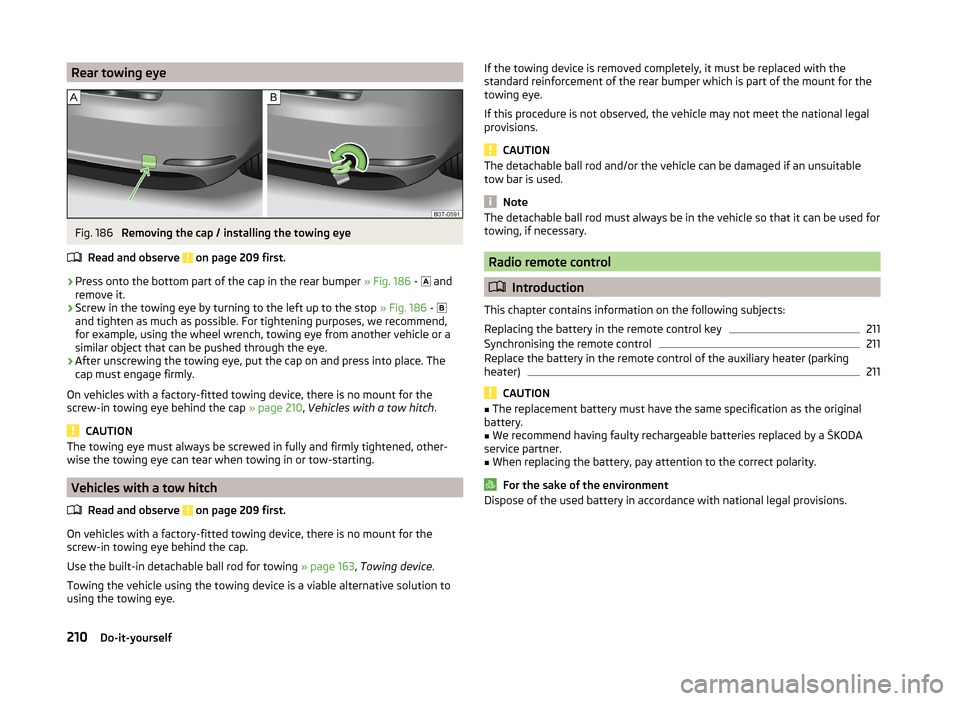
Rear towing eyeFig. 186
Removing the cap / installing the towing eye
Read and observe
on page 209 first.
›
Press onto the bottom part of the cap in the rear bumper » Fig. 186 -
and
remove it.
›
Screw in the towing eye by turning to the left up to the stop » Fig. 186 -
and tighten as much as possible. For tightening purposes, we recommend,
for example, using the wheel wrench, towing eye from another vehicle or a
similar object that can be pushed through the eye.
›
After unscrewing the towing eye, put the cap on and press into place. The
cap must engage firmly.
On vehicles with a factory-fitted towing device, there is no mount for the
screw-in towing eye behind the cap » page 210, Vehicles with a tow hitch .
CAUTION
The towing eye must always be screwed in fully and firmly tightened, other-
wise the towing eye can tear when towing in or tow-starting.
Vehicles with a tow hitch
Read and observe
on page 209 first.
On vehicles with a factory-fitted towing device, there is no mount for the
screw-in towing eye behind the cap.
Use the built-in detachable ball rod for towing » page 163, Towing device .
Towing the vehicle using the towing device is a viable alternative solution to
using the towing eye.
If the towing device is removed completely, it must be replaced with the
standard reinforcement of the rear bumper which is part of the mount for the
towing eye.
If this procedure is not observed, the vehicle may not meet the national legal
provisions.
CAUTION
The detachable ball rod and/or the vehicle can be damaged if an unsuitable
tow bar is used.
Note
The detachable ball rod must always be in the vehicle so that it can be used for
towing, if necessary.
Radio remote control
Introduction
This chapter contains information on the following subjects:
Replacing the battery in the remote control key
211
Synchronising the remote control
211
Replace the battery in the remote control of the auxiliary heater (parking
heater)
211
CAUTION
■ The replacement battery must have the same specification as the original
battery.■
We recommend having faulty rechargeable batteries replaced by a ŠKODA
service partner.
■
When replacing the battery, pay attention to the correct polarity.
For the sake of the environment
Dispose of the used battery in accordance with national legal provisions.210Do-it-yourself
Page 213 of 246
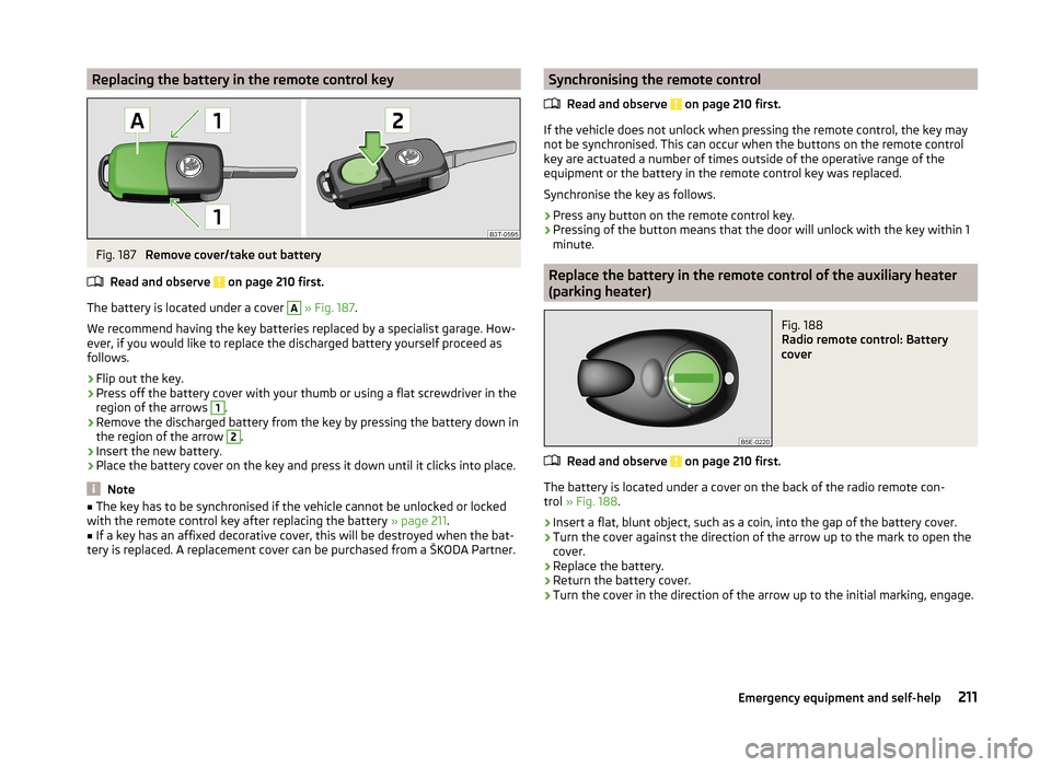
Replacing the battery in the remote control keyFig. 187
Remove cover/take out battery
Read and observe
on page 210 first.
The battery is located under a cover
A
» Fig. 187 .
We recommend having the key batteries replaced by a specialist garage. How-
ever, if you would like to replace the discharged battery yourself proceed as
follows.
›
Flip out the key.
›
Press off the battery cover with your thumb or using a flat screwdriver in the
region of the arrows
1
.
›
Remove the discharged battery from the key by pressing the battery down in
the region of the arrow
2
.
›
Insert the new battery.
›
Place the battery cover on the key and press it down until it clicks into place.
Note
■ The key has to be synchronised if the vehicle cannot be unlocked or locked
with the remote control key after replacing the battery » page 211.■
If a key has an affixed decorative cover, this will be destroyed when the bat-
tery is replaced. A replacement cover can be purchased from a ŠKODA Partner.
Synchronising the remote control
Read and observe
on page 210 first.
If the vehicle does not unlock when pressing the remote control, the key may
not be synchronised. This can occur when the buttons on the remote control
key are actuated a number of times outside of the operative range of the
equipment or the battery in the remote control key was replaced.
Synchronise the key as follows.
›
Press any button on the remote control key.
›
Pressing of the button means that the door will unlock with the key within 1
minute.
Replace the battery in the remote control of the auxiliary heater
(parking heater)
Fig. 188
Radio remote control: Battery
cover
Read and observe on page 210 first.
The battery is located under a cover on the back of the radio remote con-
trol » Fig. 188 .
›
Insert a flat, blunt object, such as a coin, into the gap of the battery cover.
›
Turn the cover against the direction of the arrow up to the mark to open the
cover.
›
Replace the battery.
›
Return the battery cover.
›
Turn the cover in the direction of the arrow up to the initial marking, engage.
211Emergency equipment and self-help
Page 214 of 246
Emergency unlocking/locking
Introduction
This chapter contains information on the following subjects:
Unlocking/locking the driver's door
212
Locking a door
212
Unlocking the tailgate
212
Selector lever-emergency unlocking
213
Unlocking/locking the driver's door
Fig. 189
Handle on the driver's door: cov-
ered locking cylinder
›
Pull on the handle.
›
Push the vehicle key into the recess on the bottom side of the cover in the
region of the arrow and fold it upwards » Fig. 189.
›
Insert the vehicle key (the buttons facing upward) into the locking cylinder
and lock/unlock the vehicle.
CAUTION
Make sure you do not damage the paint when performing an emergency lock-
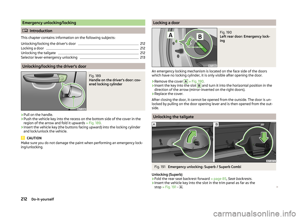
ing/unlocking.Locking a doorFig. 190
Left rear door: Emergency lock-
ing
An emergency locking mechanism is located on the face side of the doors
which have no locking cylinder, it is only visible after opening the door.
›
Remove the cover
A
» Fig. 190 .
›
Insert the key into the slot
B
and turn it into the horizontal position in the
direction of the arrow (mirror-inverted on the right doors).
›
Replace the cover.
After closing the door, it cannot be opened from the outside. The door is un-
locked by pulling on the door opening lever and is then opened from the out-
side.
Unlocking the tailgate
Fig. 191
Emergency unlocking: Superb / Superb Combi
Unlocking (Superb)
›
Fold the rear seat backrest forward » page 85, Seat backrests .
›
Insert the vehicle key into the slot in the trim panel as far as the
stop » Fig. 191 -
.
212Do-it-yourself
Page 215 of 246
›Unlock the lid by moving it in the direction of the arrow.›Open the tailgate.
Unlocking (Superb Combi)›
Fold the rear seat backrest forward » page 85, Seat backrests .
›
Insert a screwdriver or similar tool into the opening of the trim as far as it
goes » Fig. 191 -
.
›
Unlock the lid by moving it in the direction of the arrow.
›
Open the tailgate.
Selector lever-emergency unlocking
Fig. 192
Selector lever-emergency unlocking
›
Firmly apply the handbrake.
›
Grasp the cover
1
in the area of arrow
2
» Fig. 192 and carefully pull up-
wards.
›
Also unlock the cover on the other side.
›
Use a finger to press the yellow plastic part in the direction of the arrow
3
.
›
At the same time, press the locking button in the selector lever and move the selector lever to position N.
If the selector lever is moved again to position P, it is once again blocked.
Emergency operation of the sliding/tilting roof
Introduction
This chapter contains information on the following subjects:
Operation
213
Activation after un-clamping and re-clamping the battery
214
Operation
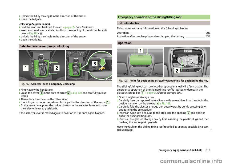
Fig. 193
Point for positioning screwdriver/opening for positioning the key
The sliding/tilting roof can be closed or opened manually if a fault occurs. The
emergency operation of the sliding/tilting roof is located underneath the
glasses storage box
1
» page 91 , Glasses storage box .
›
Open the glasses storage box.
›
Carefully insert an approximately 5 mm wide screwdriver into the slot in the
positions shown by the arrows
1
» Fig. 193 .
›
Carefully fold the glasses storage box downwards by gently pressing down
and turning the screwdriver.
›
Insert an Allen key, SW 4, up to the stop into the opening
2
and close or
open the sliding/tilting roof.
›
Reinstall the glasses storage box by first inserting the plastic plugs and then
pushing the entire part upwards.
Have the fault on the sliding tilting roof rectified as soon as possible by a spe- cialist garage.
213Emergency equipment and self-help
Page 234 of 246
Index
A
Abroad Driving abroad
150
Unleaded petrol150
ABS Operation
152
Warning light36
Accessories169
Adaptive headlights (AFS)68
Adjust Auxiliary heating (auxiliary heating and ventila-tion)
117
Adjusting Belt height
13
Exterior mirrors78
Head restraints81
Interior mirror77
Manual air conditioning112
Seats79, 80
Steering wheel8
Adjusting the seats7, 79
Adjustment Headlight beam
66
Aerial173
See windows175
AFS68
Warning light36
Airbag14
Deactivating19
Deactivating the front passenger airbag20
Deployment14
Front airbag15
Head airbag18
Indicator light38
Knee airbag16
Modifications and damage to the airbag system 171 Side airbag
17
Airbag system14
Air conditioning system108
Air outlets108
Climatronic113
Manual air conditioning system110
Air outlets108
Air recirculation Climatronic
115
Alarm Switching off
54
Triggering54
Anti-theft alarm system Activating/deactivating
54
Trailer168
Antilock brake system (ABS)152
Armrest front
85
rear85, 94
Artificial leather178
Ashtray89
ASR Warning light
35
Assist systems151
ABS36, 152
ASR35
Cruise Control System158
DSR152
EDL152
ESC35, 151
HBA152
HHC153
Park assist154
Parking aid153
START-STOP159
TCS152
Auto Check Control31
Automatic driving lamp control68
Automatic gearbox142
Selector lever-emergency unlocking213
Starting-off and driving144
Tiptronic143
Using the selector lever142
Automatic gearbox modes142
Automatic load deactivation193
Automatic retractable cargo cover (Superb Combi))
99
Automatic transmission Kickdown
144
Malfunction144
Selector lever lock143
AUX Installation in the storage compartment
90
Auxiliary heating (auxiliary heating and ventila- tion)
116
Adjust117
Radio remote control118
Switching on/off117
Avoiding damage to the vehicle Driving through water
149
Avoiding damage to your vehicle149
B
Ball head Check fitting
165
Fitting164
Ready position164
Removing165
Battery In the remote control key
211
iReplace the remote control of the auxiliary heater (parking heater)
211
Belts10
Belt tensioners13
Bonnet Closing
183
Opening183
Warning light34
Boot Automatic retraction (Superb Combi)
99
Extending variable loading floor103
232Index
Page 238 of 246
HeadlightsDriving abroad150
Headlight cleaning system77
Replacing a bulb220
Head restraint81
Heater Windscreen and rear window
73
Heating Exterior mirrors
78
Seats83
HHC153
Hill Hold Control (HHC)153
Horn27
Hydraulic Brake Assist (HBA)152
I
Ignition
136
Immobilizer136
Individual settings Locking
52
Unlocking52
Inertia reels13
Information message see KESSY
51
Information system39
Compass point display46
Display a low temperature40
Door warning41
Gear recommendation40
MAXI DOT display44
Multifunction display41
Operation40
Service interval display46
instrument cluster Auto Check Control
31
Instrument cluster28
Counter for distance driven30
Display29
Display of the second speed31
Fuel gauge30
Overview28
Revolutions counter29
see instrument cluster28
Speedometer29
Temperature gauge29
Warning lights32
Interior monitor54
Internet connection127
ISOFIX23
J
Jack
201
Jacking points Raise vehicle
203
Jump-starting207
K
KESSY
50
Information message51
Lock / unlock the steering138
Locking50
Starting the engine139
Switching off the engine139
Switch off ignition138
Switch on ignition138
Unlocking50
Key Starting the engine
136
Stopping the engine137
Knee airbag16
L
Lamp Warning light
36
Lamp failure Warning light
36
LEAVING HOME70
Lever Main beam67
Turn signal67
Windscreen wipers76
Licht COMING HOME / LEAVING HOME
70
Light Cockpit
71
Fog lights with CORNER function69
Replacing bulbs219
Travel mode69
Light bulbs Rear light (Superb Combi)
222
Lighting Luggage compartment
95
Lights65
Adaptive headlights (AFS)68
Automatic driving lamp control68
Daylight running67
Fog lights69
Hazard warning light system70
Headlight beam adjustment66
Headlight flasher67
Instrument lighting66
Low beam lights66
Main beam67
Parking lights66, 71
Rear fog light69
Switching on and off66
Tourist lights69
Turn signal67
Warning lights32
Lock Remote control
49
Vehicle key49
Locking Individual settings
52
KESSY50
Locking and unlocking the vehicle from the in- side
52
236Index
Page 240 of 246
Passive safetyBefore setting off6
Driving safety6
Safety equipment6
Passive Safety6
Payload224
Pedals142
Footmats142
Petrol refer to Fuel
180
Polishing the paintwork See Taking care of your vehicle
174
Power outlet 12 V
90
Power Steering / steering lock (KESSY system) warning light
34
Power windows Button in the front passenger door
61
Practical features86
12-Volt power outlet90
Storage compartment for umbrella93
Storage compartment in rear centre console93
Storage compartment on the passenger side92
Storage compartment under the armrest, front 90
Storage compartment under the passenger seat
92
Storage net in the front centre console91
Storage pockets on the front seats93
R
Radiator fan
184
Radio reception See windows
175
Radio remote control Auxiliary heating
118
Raise vehicle203
Rear-view mirror Exterior mirrors78
Fold in passenger mirror78
Synchronous adjustment of the rear-view mir- ror
78
Rear fog light69
Warning light36
Rear interior light72
Rear mirror77
Interior mirror77
Rear seats Seat folded forward Combi
86
Rear window - heater73
Recirculated air mode Manual air conditioning
112
Refuelling180
Fuel180
Remote control lock
49
Replacing the battery211
Synchronisation process211
unlock49
Remote control key Replacing the battery
211
Removable lights (Superb Combi) Changing rechargeable light batteries
101
Removable Light (Superb Combi) Remove light
101
Removable ski bag95
Removable variable loading floor Fit and remove
104
Repairs and technical alterations169
Replace Vehicle battery
192
Replacing Bulb for main beam
221
Bulb for main beam and daytime running lights 220
Bulb for the fog light
221
Bulb for the licence plate light222
Bulb in rear light (Superb Combi)223
Bulbs219
Fuses215
Fuses in the dash panel216
Fuses in the engine compartment217
Low beam bulb220
Wiper blades214
Replenishing Coolant
188
Engine oil187
Windscreen washer fluid184
Revolutions counter29
Roof luggage rack Attachment points
107
Roof rack system106
Roof load107
Running-in The first 1500 km
145
Running in Brake pads
145
Engine145
Tyres145
S
SAFE see Safe securing
51
SAFELOCK see Safe securing
51
Safe securing51
Safety6
Child safety21
Child safety seats21
Correct seated position7
Head restraints81
ISOFIX23
TOP TETHER24
Saving electrical energy146
Screens see Sun screen in the rear doors
74
Seals Taking care of your vehicle
174
238Index