key SKODA SUPERB 2014 2.G / (B6/3T) Service Manual
[x] Cancel search | Manufacturer: SKODA, Model Year: 2014, Model line: SUPERB, Model: SKODA SUPERB 2014 2.G / (B6/3T)Pages: 246, PDF Size: 17.16 MB
Page 138 of 246
Electronic immobilizerRead and observe
and on page 135 first.
An electronic chip is integrated in the head of the key. The immobiliser is deac-
tivated with the aid of this chip when the key is inserted in the ignition lock.
The electronic immobiliser is automatically activated when the ignition key is
withdrawn from the lock.
The engine will not start if a non-authorized ignition key is used.
The following message is shown in the information cluster display. Immobilizer active.
IMMOBILISER
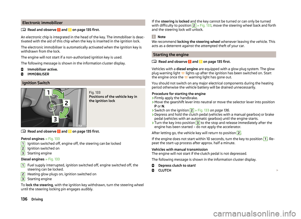
Ignition Switch
Fig. 133
Positions of the vehicle key in
the ignition lock
Read and observe and on page 135 first.
Petrol engines » Fig. 133
Ignition switched off, engine off, the steering can be locked
Ignition switched on
Starting engine
Diesel engines » Fig. 133
Fuel supply interrupted, ignition switched off, engine switched off, the
steering can be locked.
Heating glow plugs on, ignition switched on
Starting engine
To lock the steering , with the ignition key withdrawn, turn the steering wheel
until the steering locking pin engages audibly.
123123If the steering is locked and the key cannot be turned or can only be turned
with difficulty to position 2 » Fig. 133 , move the steering wheel back and forth
and the steering lock will unlock.
Note
We recommend locking the steering wheel whenever leaving the vehicle. This
acts as a deterrent against the attempted theft of your car.
Starting the engine
Read and observe
and on page 135 first.
Vehicles with a diesel engine are equipped with a glow plug system. The glow
plug warning light lights up after the ignition has been switched on. Start
the engine once the warning light has gone out.
You should not switch on any major electrical components during the heating
period otherwise the vehicle battery will be drained unnecessarily.
Procedure for starting the engine
›
Firmly apply the handbrake.
›
Move the gearshift lever into neutral or move the selector lever into position
P or N.
›
Switch on the ignition
2
» Fig. 133 on page 136 .
›
Depress and hold the clutch pedal (vehicles with a manual gearbox) or brake
pedal (vehicles with an automatic gearbox) until the engine starts.
›
Turn the key into position
3
to the stop and release immediately after the
engine has been started – do not apply the accelerator.
After letting go, the vehicle key will return to position
2
.
If the engine does not start within 10 seconds, turn the key to position
1
. Re-
peat the start-up process after approx. half a minute.
Vehicles with manual transmission
The engine will not start if the clutch pedal is not depressed.
The following message is shown in the information cluster display. Depress clutch to start!
CLUTCH
136Driving
Page 139 of 246
Vehicles with automatic transmission1)
The engine will not start if the brake pedal is not depressed.
The following message is shown in the information cluster display. Depress brake to start!
BRAKE
CAUTION
■ If the engine does not start up after a second attempt, one of the following
fuses may be defective. ■ Petrol engine - fuse for the electric fuel pump.
■ Diesel engine - fuse for the control unit for glow plugs or glow plug relay
and fuel pump.■
Check the fuse and replace if necessary » page 215, or seek assistance from
a specialist garage.
Stopping the engine
Read and observe
and on page 135 first.
Switch off the engine by turning the ignition key to position
1
» Fig. 133 on
page 136 .
For vehicles with automatic transmission, the ignition key can only be removed
if the selector lever is in position P.
Starting and stopping the engine - KESSY
Introduction
This chapter contains information on the following subjects:
Steering lock / unlock
138
Ignition on/off
138
Starting the engine
139
Switching off the engine
139
Emergency start-up of the engine
139
Emergency ignition shutoff system
140The KESSY system (Keyless Entry Exit System, hereinafter referred to only as
system) allows the switching on or switching off of the ignition and starting or
stopping of the engine without the active use of the key.
A key must be in the vehicle to unlock the steering, switch on the ignition and
start the vehicle. When travelling the key must be in the vehicle.
The engine running noises may louder at first be louder for a short time after starting the cold engine. This is quite normal and is not an operating problem.WARNING■ Never leave the key in the vehicle when you exit the vehicle. Unauthor-
ized persons, such as children, for example, could lock the car, turn on the
ignition or start the engine - there is a danger of injury and accidents!■
Never leave the vehicle unattended with the engine running - there is a
risk of theft etc!
■
Never switch off the engine before the vehicle is stationary – risk of acci-
dent!
WARNING■ Never leave the engine running in unventilated or closed rooms. The ex-
haust gases from the engine contain substances such as odourless and col-
ourless carbon monoxide (a poisonous gas) – risk to life! ■Carbon monoxide can cause unconsciousness and death.
CAUTION
■ The system can recognize the valid key, even if it has been forgotten, for ex-
ample, in the front of the vehicle roof D » Fig. 32 on page 50 - There is danger
of loss or damage to the key! It is therefore not always necessary to know
where the key is.■
The starter must only be operated when the engine is not running and the
vehicle is at a standstill. The starter or engine may be damaged if the starter is
activated when the engine is running.
■
Do not tow start the engine – there is a risk of damaging the engine and the
catalytic converter. The battery from another vehicle can be used as a jump-
start aid » page 207 , Jump-starting .
1)
Applies to vehicles with START-STOP system.
137Starting-off and Driving
Page 141 of 246
If the driver's door is opened while the igition is on, an audible signal sounds
and the following message appears in the instrument cluster display.
Ignition on!
IGNITION ON
When leaving the vehicle always switch off the ignition.
Note
The ignition is switched on when indicated by the lighting up of certain indica-
tor lamps in the instrument cluster.
Starting the engine
Read and observe
and on page 137 first.
Vehicles with a diesel engine are equipped with a glow plug system. The glow
plug warning light lights up after the ignition has been switched on. Start
the engine once the warning light has gone out.
You should not switch on any major electrical components during the heating
period otherwise the vehicle battery will be drained unnecessarily.
Procedure for starting the engine
›
Firmly apply the handbrake.
›
Move the gearshift lever into neutral or move the selector lever into position
P or N.
›
Depress and hold the clutch pedal (vehicles with a manual gearbox) or brake
pedal (vehicles with an automatic gearbox) until the engine starts.
›
Press and hold » Fig. 134 on page 138 1)
the starter button until the engine
starts.
CAUTION
■ If the engine does not start up after a second attempt, one of the following
fuses may be defective. ■ Petrol engine - fuse for the electric fuel pump.
■ Diesel engine - fuse for the control unit for glow plugs or glow plug relay
and fuel pump.■
Check the fuse and replace if necessary » page 215, or seek assistance from
a specialist garage.
Switching off the engine
Read and observe
and on page 137 first.
›
Stop the vehicle.
›
Press the starter button » Fig. 134 on page 138 briefly.
The engine and the ignition are switched off simultaneously.
The engine can be switched off up to a speed of 2 km/h.
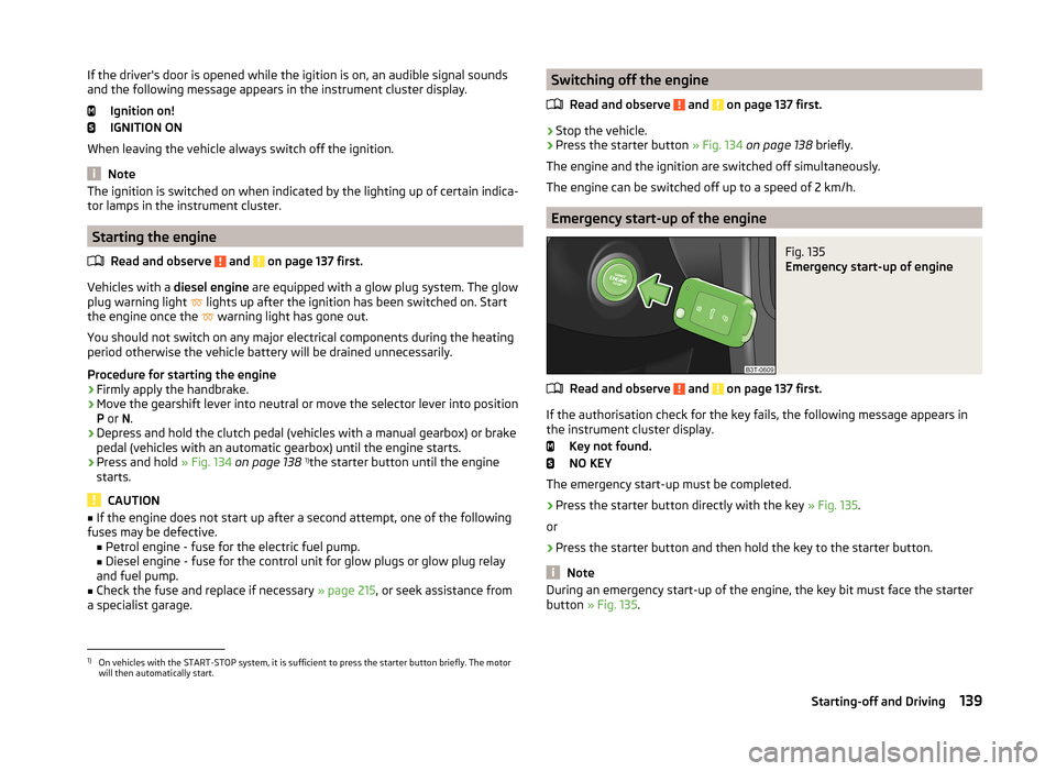
Emergency start-up of the engine
Fig. 135
Emergency start-up of engine
Read and observe and on page 137 first.
If the authorisation check for the key fails, the following message appears in
the instrument cluster display.
Key not found.
NO KEY
The emergency start-up must be completed.
› Press the starter button directly with the key
» Fig. 135.
or
› Press the starter button and then hold the key to the starter button.
Note
During an emergency start-up of the engine, the key bit must face the starter
button » Fig. 135 .1)
On vehicles with the START-STOP system, it is sufficient to press the starter button briefly. The motor
will then automatically start.
139Starting-off and Driving
Page 144 of 246
WARNINGNever engage reverse gear when driving – risk of accident!
CAUTION
If not in the process of changing gear, do not leave your hand on the gearshift
lever while driving. The pressure from the hand can cause the gearshift mech-
anism to wear excessively.
Pedals
The operation of the pedals must not be hindered under any circumstances!
In the driver's footwell, only a footmat, which is attached to the two corre-
sponding attachment points, may be used.
Only use factory-supplied footmats or footmats from the range of ŠKODAOrigi-
nal Accessories, which are fitted to two attachment points.
WARNINGNo objects may be placed in the driver's footwell – risk due to obstruction
or limitation of pedal operation.
Automatic gearbox
Introduction
This chapter contains information on the following subjects:
Modes and use of selector lever
142
Manual shifting of gears (Tiptronic)
143
Starting-off and driving
144
Malfunction
144WARNING■ Do not depress the accelerator if changing the forward driving mode –
risk of accident!■
Never move the selector lever to mode R or P when driving – risk of acci-
dent!
■
When the vehicle is stationery and the engine is running, the vehicle must
be held in mode D, S or R with the brake pedal. Even when the engine is
idling, the power transmission is never completely interrupted – the vehicle
creeps.
CAUTION■ If the selector lever is moved to mode N while driving, the accelerator pedal
must be released and you will need to wait until the engine has reached its
idling speed before moving the selector lever to a forward driving mode again.■
At temperatures below -10 °C, the engine can only be started in the selector
lever position P.
■
When stopping on a slope, never try to hold the vehicle using the accelerator
pedal – this may lead to gear damage.
Note
After the ignition is switched off, the ignition key can only be withdrawn if the
selector lever is in the position P.
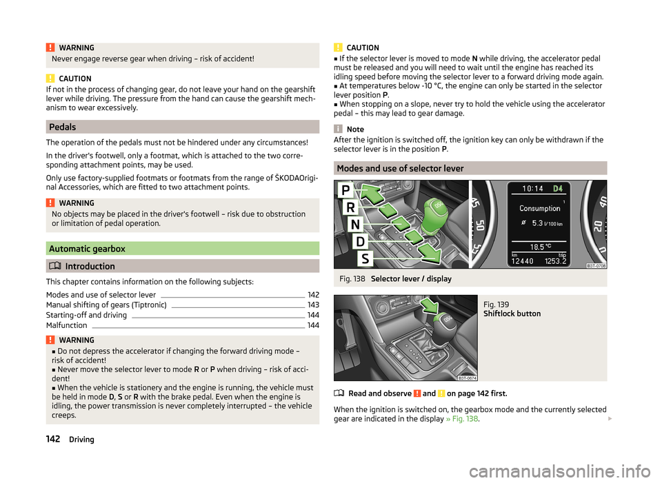
Modes and use of selector lever
Fig. 138
Selector lever / display
Fig. 139
Shiftlock button
Read and observe and on page 142 first.
When the ignition is switched on, the gearbox mode and the currently selected
gear are indicated in the display » Fig. 138.
142Driving
Page 158 of 246
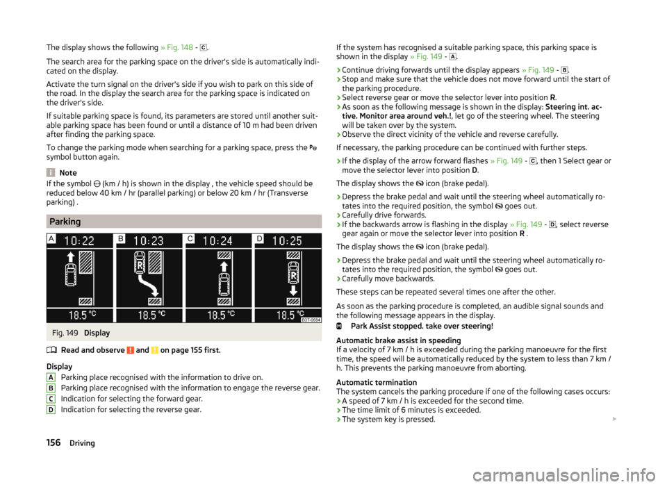
The display shows the following » Fig. 148 - .
The search area for the parking space on the driver's side is automatically indi- cated on the display.
Activate the turn signal on the driver's side if you wish to park on this side of
the road. In the display the search area for the parking space is indicated on
the driver's side.
If suitable parking space is found, its parameters are stored until another suit-
able parking space has been found or until a distance of 10 m had been driven
after finding the parking space.
To change the parking mode when searching for a parking space, press the
symbol button again.
Note
If the symbol (km / h) is shown in the display , the vehicle speed should be
reduced below 40 km / hr (parallel parking) or below 20 km / hr (Transverse
parking) .
Parking
Fig. 149
Display
Read and observe
and on page 155 first.
Display Parking place recognised with the information to drive on.
Parking place recognised with the information to engage the reverse gear.
Indication for selecting the forward gear.
Indication for selecting the reverse gear.
ABCDIf the system has recognised a suitable parking space, this parking space is
shown in the display » Fig. 149 - .›
Continue driving forwards until the display appears » Fig. 149 -
.
›
Stop and make sure that the vehicle does not move forward until the start of
the parking procedure.
›
Select reverse gear or move the selector lever into position R.
›
As soon as the following message is shown in the display: Steering int. ac-
tive. Monitor area around veh.! , let go of the steering wheel. The steering
will be taken over by the system.
›
Observe the direct vicinity of the vehicle and reverse carefully.
If necessary, the parking procedure can be continued with further steps.
›
If the display of the arrow forward flashes » Fig. 149 -
, then 1 Select gear or
move the selector lever into position D.
The display shows the icon (brake pedal).
›
Depress the brake pedal and wait until the steering wheel automatically ro-
tates into the required position, the symbol goes out.
›
Carefully drive forwards.
›
If the backwards arrow is flashing in the display
» Fig. 149 -
, select reverse
gear again or move the selector lever into position R .
The display shows the icon (brake pedal).
›
Depress the brake pedal and wait until the steering wheel automatically ro-
tates into the required position, the symbol goes out.
›
Carefully move backwards.
These steps can be repeated several times one after the other.
As soon as the parking procedure is completed, an audible signal sounds and
the following message appears in the display.
Park Assist stopped. take over steering!
Automatic brake assist in speeding
If a velocity of 7 km / h is exceeded during the parking manoeuvre for the first
time, the speed will be automatically reduced by the system to less than 7 km /
h. This prevents the parking manoeuvre from aborting.
Automatic termination
The system cancels the parking procedure if one of the following cases occurs:
› A speed of 7 km / h is exceeded for the second time.
› The time limit of 6 minutes is exceeded.
› The system key is pressed.
156Driving
Page 159 of 246
›The ASR system is turned off.
› There is a driver intervention in the automatic steering operation (wheel
stop).
› When there is a system fault (system temporarily not available).
› There is an automatic emergency braking.
If any of the above events occurs, the following message is dis-
played » page 157 .
Departing from a parallel parking space
Read and observe
and on page 155 first.
Manoeuvring out
›
Press the symbol button » Fig. 148 on page 155
once .
›
Activate the turn signal for side of the vehicle where the parking space is out
of which you wish to manoeuvre.
›
Select reverse gear or move the selector lever into position R.
›
As soon as the following message is shown in the display: Steering int. ac-
tive. Monitor area around veh.! , let go of the steering wheel. The steering
will be taken over by the system.
›
Observe the direct vicinity of the vehicle and reverse carefully.
›
Follow the system instructions shown in the display.
As soon as the parking procedure is completed, an audible signal sounds and
the following message appears in the information display:
Please take over steering and drive on.
Automatic termination
The system terminates the manoeuvring procedure if one of the following ca-
ses arises.
› The system key is pressed.
› The ASR system is turned off.
› There is a driver intervention in the automatic steering operation (wheel
stop).
› When there is a system fault (system temporarily not available).
› There is an automatic emergency braking.
If any of the above events occurs, the following message is dis-
played » page 157 .
Automatic emergency braking
Read and observe
and on page 155 first.
If the system detects a risk of collision during parking, automatic emergencybraking takes place to prevent a collision.
The parking is terminated by the emergency braking.
CAUTION
If the parking is aborted due to the speed exceeding 7 km / h for the second
speed, then the automatic emergency braking is not triggered by the system!
Information messages
Read and observe
and on page 155 first.
Park Assist: Speed too high.
If a speed of 50 km / h is exceeded while searching for a parking space, the
system with the key symbol is must be reactivated.
Speed too high. take over steering!
The parking is terminated if the speed exceeds 7 km / hr. Steering intervention by the driver: take over steering!
The parking procedure is terminated due to a driver steering intervention. Park Assist stopped. ASR deactivated.
The parking procedure cannot be carried out because the TCS system is deac-
tivated. Activate the TCS.
ASR deactivated. take over steering!
The parking procedure was ended because TCS was deactivated during the parking procedure.
Trailer: Park Assist stopped.
The parking procedure cannot be carried out because a trailer is hitched. Time limit exceeded. take over steering!
The parking procedure was ended because the time limit of 6 minutes was
passed.
Park Assist currently not available.
157Assist systems
Page 165 of 246
Towing a trailer
Towing device
Introduction
This chapter contains information on the following subjects:
Description
163
Adjusting the ready position
164
Fitting the ball head
164
Check proper fitting
165
Removing the ball head
165
Use and care
166
If your vehicle has already been factory-fitted with a towing device or is fitted
with a towing device from ŠKODA Original Accessories, then it meets all of the
technical requirements and national legal regulations for towing a trailer.
Your vehicle is fitted with a 13-pin power socket for the electrical connection
between the vehicle and trailer. If the trailer that is to be towed has a 7-pin
connector , you can use a suitable adapter from ŠKODA Original Accessories.
The maximum trailer drawbar load is 80 kg.
WARNING■
Check that the tow bar is seated correctly and is secured in the mounting
recess before the start of every journey.■
Do not use the tow bar if it is not correctly inserted and secured in the
mounting recess.
■
Do not use the towing device if it is damaged or if there are parts missing.
■
Do not modify or adapt the towing device in any way.
■
Never release the tow bar while the trailer is still coupled.
CAUTION
Take care when handling the tow bar so as to avoid damaging the paintwork
on the bumper.DescriptionFig. 153
Carrier for the towing device/tow bar
Read and observe
and on page 163 first.
The tow bar can be removed and is kept in the spare wheel compartment or in
a compartment for the spare wheel in the boot » page 201, Vehicle tool kit .
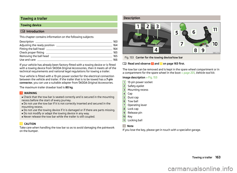
Image description » Fig. 153
13-pin power socket
Safety eyelet
Mounting recess
Cap
Dust cap
Tow ball
Operating lever
Lock cap
Release pin
Key
Locking ball
Note
If you lose the key, please get in touch with a specialist garage.1234567891011163Towing a trailer
Page 166 of 246
Adjusting the ready positionFig. 154
Setting the ready position/ready position
Read and observe
and on page 163 first.
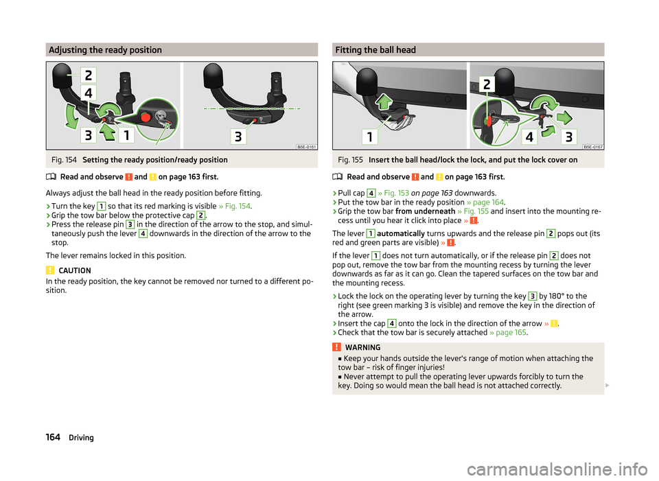
Always adjust the ball head in the ready position before fitting.
›
Turn the key
1
so that its red marking is visible » Fig. 154.
›
Grip the tow bar below the protective cap
2
.
›
Press the release pin
3
in the direction of the arrow to the stop, and simul-
taneously push the lever
4
downwards in the direction of the arrow to the
stop.
The lever remains locked in this position.
CAUTION
In the ready position, the key cannot be removed nor turned to a different po-
sition.Fitting the ball headFig. 155
Insert the ball head/lock the lock, and put the lock cover on
Read and observe
and on page 163 first.
›
Pull cap
4
» Fig. 153 on page 163 downwards.
›
Put the tow bar in the ready position » page 164.
›
Grip the tow bar from underneath » Fig. 155 and insert into the mounting re-
cess until you hear it click into place » .
The lever
1
automatically turns upwards and the release pin
2
pops out (its
red and green parts are visible) » .
If the lever
1
does not turn automatically, or if the release pin
2
does not
pop out, remove the tow bar from the mounting recess by turning the lever
downwards as far as it can go. Clean the tapered surfaces on the tow bar and
the mounting recess.
›
Lock the lock on the operating lever by turning the key
3
by 180° to the
right (see green marking 3 is visible) and remove the key in the direction of
the arrow.
›
Insert the cap
4
onto the lock in the direction of the arrow » .
›
Check that the tow bar is securely attached » page 165.
WARNING■
Keep your hands outside the lever's range of motion when attaching the
tow bar – risk of finger injuries!■
Never attempt to pull the operating lever upwards forcibly to turn the
key. Doing so would mean the ball head is not attached correctly.
164Driving
Page 167 of 246
CAUTION■After removing the key, always replace the cap on the lock of the operating
lever – risk of dirt getting into the lock.■
Keep the mounting recess of the towing equipment clean at all times. Such
dirt prevents the ball head from being attached securely.
■
After removing the ball head, always place the cap on the mounting recess.
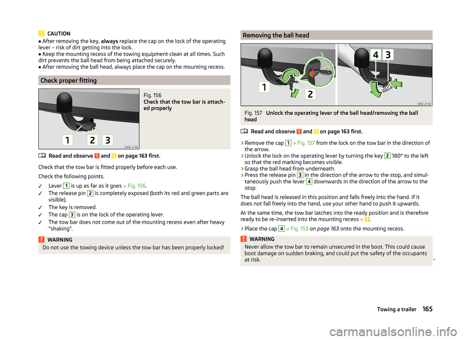
Check proper fitting
Fig. 156
Check that the tow bar is attach-
ed properly
Read and observe and on page 163 first.
Check that the tow bar is fitted properly before each use.
Check the following points. Lever
1
is up as far as it goes » Fig. 156.
The release pin
2
is completely exposed (both its red and green parts are
visible).
The key is removed.
The cap
3
is on the lock of the operating lever.
The tow bar does not come out of the mounting recess even after heavy
“shaking”.
WARNINGDo not use the towing device unless the tow bar has been properly locked!Removing the ball headFig. 157
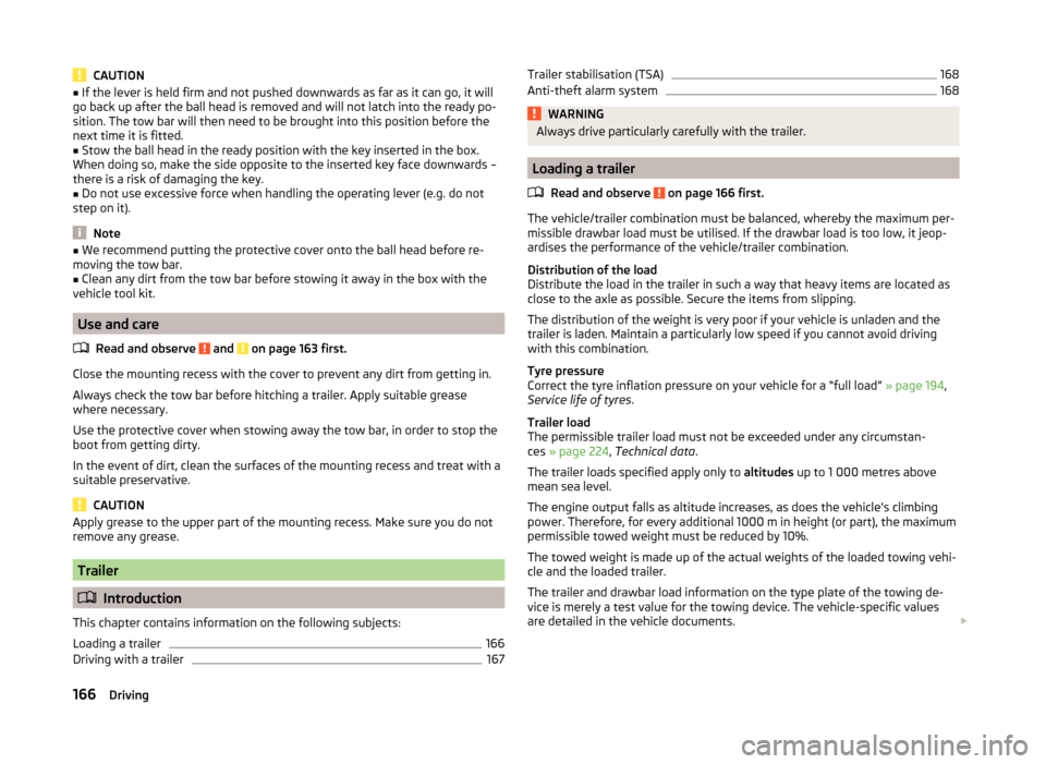
Unlock the operating lever of the ball head/removing the ball
head
Read and observe
and on page 163 first.
›
Remove the cap
1
» Fig. 157 from the lock on the tow bar in the direction of
the arrow.
›
Unlock the lock on the operating lever by turning the key
2
180° to the left
so that the red marking becomes visible.
›
Grasp the ball head from underneath.
›
Press the release pin
3
in the direction of the arrow to the stop, and simul-
taneously push the lever
4
downwards in the direction of the arrow to the
stop.
The ball head is released in this position and falls freely into the hand. If it
does not fall freely into the hand, use your other hand to push it upwards.
At the same time, the tow bar latches into the ready position and is therefore
ready to be re-inserted into the mounting recess »
.
›
Place the cap
4
» Fig. 153 on page 163 onto the mounting recess.
WARNINGNever allow the tow bar to remain unsecured in the boot. This could cause
boot damage on sudden braking, and could put the safety of the occupants
at risk. 165Towing a trailer
Page 168 of 246
CAUTION■If the lever is held firm and not pushed downwards as far as it can go, it will
go back up after the ball head is removed and will not latch into the ready po-
sition. The tow bar will then need to be brought into this position before the
next time it is fitted.■
Stow the ball head in the ready position with the key inserted in the box.
When doing so, make the side opposite to the inserted key face downwards –
there is a risk of damaging the key.
■
Do not use excessive force when handling the operating lever (e.g. do not
step on it).
Note
■ We recommend putting the protective cover onto the ball head before re-
moving the tow bar.■
Clean any dirt from the tow bar before stowing it away in the box with the
vehicle tool kit.
Use and care
Read and observe
and on page 163 first.
Close the mounting recess with the cover to prevent any dirt from getting in.
Always check the tow bar before hitching a trailer. Apply suitable grease
where necessary.
Use the protective cover when stowing away the tow bar, in order to stop the
boot from getting dirty.
In the event of dirt, clean the surfaces of the mounting recess and treat with a
suitable preservative.
CAUTION
Apply grease to the upper part of the mounting recess. Make sure you do not
remove any grease.
Trailer
Introduction
This chapter contains information on the following subjects:
Loading a trailer
166
Driving with a trailer
167Trailer stabilisation (TSA)168Anti-theft alarm system168WARNINGAlways drive particularly carefully with the trailer.
Loading a trailer
Read and observe
on page 166 first.
The vehicle/trailer combination must be balanced, whereby the maximum per-
missible drawbar load must be utilised. If the drawbar load is too low, it jeop-
ardises the performance of the vehicle/trailer combination.
Distribution of the load
Distribute the load in the trailer in such a way that heavy items are located as
close to the axle as possible. Secure the items from slipping.
The distribution of the weight is very poor if your vehicle is unladen and the
trailer is laden. Maintain a particularly low speed if you cannot avoid driving
with this combination.
Tyre pressure
Correct the tyre inflation pressure on your vehicle for a “full load” » page 194,
Service life of tyres .
Trailer load
The permissible trailer load must not be exceeded under any circumstan- ces » page 224 , Technical data .
The trailer loads specified apply only to altitudes up to 1 000 metres above
mean sea level.
The engine output falls as altitude increases, as does the vehicle's climbing
power. Therefore, for every additional 1000 m in height (or part), the maximum
permissible towed weight must be reduced by 10%.
The towed weight is made up of the actual weights of the loaded towing vehi-
cle and the loaded trailer.
The trailer and drawbar load information on the type plate of the towing de-
vice is merely a test value for the towing device. The vehicle-specific values
are detailed in the vehicle documents.
166Driving