key SKODA SUPERB 2014 2.G / (B6/3T) Owner's Guide
[x] Cancel search | Manufacturer: SKODA, Model Year: 2014, Model line: SUPERB, Model: SKODA SUPERB 2014 2.G / (B6/3T)Pages: 246, PDF Size: 17.16 MB
Page 81 of 246
CAUTION■The exterior mirrors with fold-in function never mechanically fold by hand
- there is a risk of damaging the electric mirror actuator!■
When the mirror is swung by external influences (due to impact during ma-
noeuvring, for example), then first fold-in the mirror by turning the knob and
wait for a loud clapping noise.
Note
■ The mirror heater only operates when the engine is running and up to an
outside temperature of +35 ℃.■
If the electrical mirror setting fails at any time, the mirrors can be adjusted by
hand by pressing on the edge of the mirror surface.
Seats and useful equipment
Adjusting the seats
Introduction
This chapter contains information on the following subjects:
Manually adjusting the front seats
80
Electric front seat adjustment
80
Head restraints
81
Memory function of the electrically adjustable seat
82
Memory function of the remote control key
82
The driver's seat should be adjusted in such a way that the pedals can be fully
pressed to the floor with slightly bent legs.
The seat backrest on the driver's seat should be adjusted in such a way that the upper point of the steering wheel can be easily reached with slightly bent
arms.
Correct adjustment of the seats is particularly important for the following rea-
sons.
› Reaching the controls safely and quickly.
› A relaxed and fatigue-free body position.
› Achieving the maximum protection offered by the seat belts and the airbag
system.
WARNING■ Only adjust the driver's seat when the vehicle is stationary – risk of acci-
dent!■
Caution when adjusting the seat! You may suffer injuries or bruises as a
result of adjusting the seat without paying proper attention.
■
The electric front seat adjustment is still functional if the ignition is
switched off (even with the ignition key removed). Therefore, when leaving
the vehicle, never leave people who are not completely independent, such
as children, unattended in the vehicle - there is a danger of injury!
■
Never carry more people than the number of seats in the vehicle.
■
Do not carry any objects on the front passenger seat except objects de-
signed for this purpose (e.g. child seats) – risk of accident!
79Seats and useful equipment
Page 82 of 246
Note■After a certain time, play can develop within the adjustment mechanism of
the backrest angle.■
For safety reasons, it is not possible to store the seat position in the electric
seat memory and remote control key memory if the inclination angle of the
seat backrest is more than 102° in relation to the seat cushion.
■
Each time you store the position of the electrically adjustable driver's seat
and exterior mirrors, the existing setting is deleted.
Manually adjusting the front seats
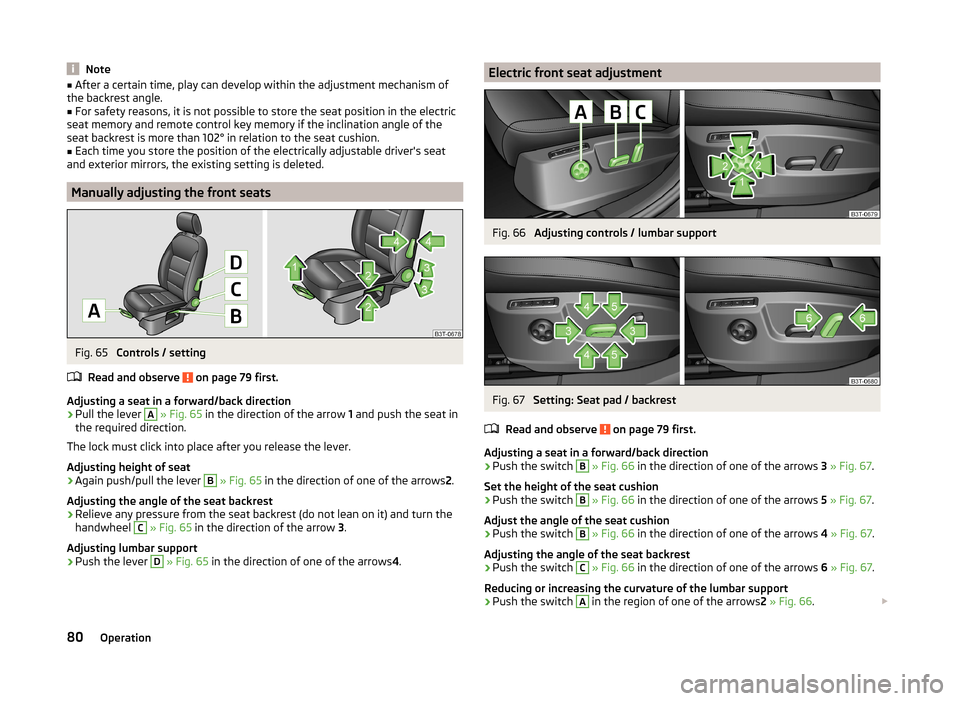
Fig. 65
Controls / setting
Read and observe
on page 79 first.
Adjusting a seat in a forward/back direction
›
Pull the lever
A
» Fig. 65 in the direction of the arrow 1 and push the seat in
the required direction.
The lock must click into place after you release the lever.
Adjusting height of seat
›
Again push/pull the lever
B
» Fig. 65 in the direction of one of the arrows 2.
Adjusting the angle of the seat backrest
›
Relieve any pressure from the seat backrest (do not lean on it) and turn the
handwheel
C
» Fig. 65 in the direction of the arrow 3.
Adjusting lumbar support
›
Push the lever
D
» Fig. 65 in the direction of one of the arrows 4.
Electric front seat adjustmentFig. 66
Adjusting controls / lumbar support
Fig. 67
Setting: Seat pad / backrest
Read and observe
on page 79 first.
Adjusting a seat in a forward/back direction
›
Push the switch
B
» Fig. 66 in the direction of one of the arrows 3 » Fig. 67 .
Set the height of the seat cushion
›
Push the switch
B
» Fig. 66 in the direction of one of the arrows 5 » Fig. 67 .
Adjust the angle of the seat cushion
›
Push the switch
B
» Fig. 66 in the direction of one of the arrows 4 » Fig. 67 .
Adjusting the angle of the seat backrest
›
Push the switch
C
» Fig. 66 in the direction of one of the arrows 6 » Fig. 67 .
Reducing or increasing the curvature of the lumbar support
›
Push the switch
A
in the region of one of the arrows 2 » Fig. 66 .
80Operation
Page 83 of 246
Raising or lowering the curvature of the lumbar support›Push the switch A in the region of one of the arrows1 » Fig. 66 .
The adjusted driver's seat position can be set in the memory of the
seat » page 82 or the remote control key » page 82.
Note
If the setting procedure is interrupted, you will need to press the button again.
Head restraints
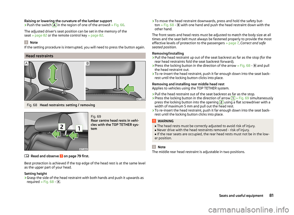
Fig. 68
Head restraints: setting / removing
Fig. 69
Rear centre head rests in vehi-
cles with the TOP TETHER sys-
tem
Read and observe on page 79 first.
Best protection is achieved if the top edge of the head rest is at the same level
as the upper part of your head.
Setting height
›
Grasp the side of the head restraint with both hands and push it upwards as
required » Fig. 68 -
.
›To move the head restraint downwards, press and hold the safety but-
ton » Fig. 68 - with one hand and push the head restraint down with the
other hand.
The front seats and head rests must be adjusted to match the body size at all
times and the seat belt must always be fastened properly to provide the most
effective levels of protection to the passengers » page 7, Correct and safe
seated position .
Removing/installing›
Pull the head restraint up out of the seat backrest as far as the stop (for the
rear head restraints fold the seat backrest forward).
›
Press the locking button in the direction of the arrow » Fig. 68 -
and pull
the head restraint out.
›
To re-insert the head restraint, push it far enough down into the seat back-
rest until the locking button clicks into place.
Removing and installing rear middle head rest
Applies to vehicles using the TOP TETHER system.
›
Pull the head restraint out of the seat backrest as far as the stop.
›
Press the locking button in the direction of arrow
1
» Fig. 69 simultaneously
press the locking button into the opening
2
using a flat screwdriver with a
width of maximum 5 mm and pull out the head rest.
›
To re-insert the head restraint, push it far enough down into the seat back-
rest until the locking button clicks into place.
WARNING■ The head rests must be correctly adjusted to avoid risk of injury.■Never drive with the head restraints removed - risk of injury.■
If the rear seats are occupied, the rear head rests must not be in the low-
er position.
Note
The middle rear head restraint is adjustable in two positions.81Seats and useful equipment
Page 84 of 246
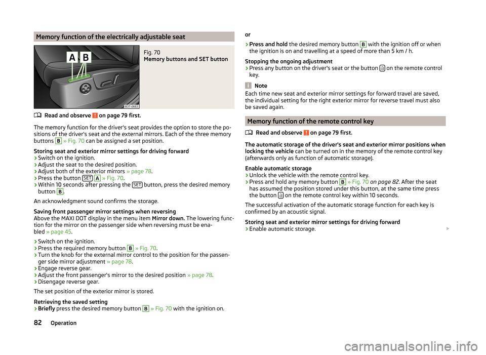
Memory function of the electrically adjustable seatFig. 70
Memory buttons and SET button
Read and observe on page 79 first.
The memory function for the driver's seat provides the option to store the po-
sitions of the driver's seat and the external mirrors. Each of the three memory
buttons
B
» Fig. 70 can be assigned a set position.
Storing seat and exterior mirror settings for driving forward
›
Switch on the ignition.
›
Adjust the seat to the desired position.
›
Adjust both of the exterior mirrors » page 78.
›
Press the button SET
A
» Fig. 70 .
›
Within 10 seconds after pressing the SET button, press the desired memory
button
B
.
An acknowledgment sound confirms the storage.
Saving front passenger mirror settings when reversing
Above the MAXI DOT display in the menu item Mirror down. The lowering func-
tion for the mirror on the passenger side when reversing must be ena-
bled » page 45 .
›
Switch on the ignition.
›
Press the required memory button
B
» Fig. 70 .
›
Turn the knob for the external mirror control to the position for the passen-
ger side mirror adjustment » page 78.
›
Engage reverse gear.
›
Adjust the front passenger's mirror to the desired position » page 78.
›
Disengage reverse gear.
The set position of the exterior mirror is stored.
Retrieving the saved setting
›
Briefly press the desired memory button
B
» Fig. 70 with the ignition on.
or›
Press and hold the desired memory button
B
with the ignition off or when
the ignition is on and travelling at a speed of more than 5 km / h.
Stopping the ongoing adjustment
›
Press any button on the driver's seat or the button on the remote control
key.
Note
Each time new seat and exterior mirror settings for forward travel are saved,
the individual setting for the right exterior mirror for reverse travel must also
be saved again.
Memory function of the remote control key
Read and observe
on page 79 first.
The automatic storage of the driver's seat and exterior mirror positions when
locking the vehicle can be turned on in the memory of the remote control key
(afterwards only as function of automatic storage).
Enable automatic storage
›
Unlock the vehicle with the remote control key.
›
Press and hold any memory button
B
» Fig. 70 on page 82 . After the seat
has assumed the position stored under this button, at the same time press
the button
on the remote control key within 10 seconds.
The successful activation of the automatic storage function for each key is
confirmed by an acoustic signal.
Storing seat and exterior mirror settings for driving forward
›
Enable automatic storage.
82Operation
Page 85 of 246
When automatic storage is activated, the current positions of the driver's seat
and the external mirrors are saved in the memory of the remote control key
each time the vehicle is locked. When the vehicle is next unlocked using the
same key, the driver's seat and the external mirrors assume the positions stor-
ed in the memory of this key 1)
.
Saving front passenger mirror settings when reversing
Above the MAXI DOT display in the menu item Mirror down. The lowering func-
tion for the mirror on the passenger side when reversing must be ena-
bled » page 45 .›
Unlock the vehicle with the remote control key.
›
Switch on the ignition.
›
Turn the knob for the external mirror control to the position for the passen-
ger side mirror adjustment » page 78.
›
Engage reverse gear.
›
Adjust the front passenger's mirror to the desired position » page 78.
›
Disengage reverse gear.
The adjusted position of the exterior mirror is stored in the remote control key
memory.
Disable the function of automatic storage
›
Unlock the vehicle with the remote control key.
›
Press and hold the SET button
A
» Fig. 70 on page 82 . At the same time,
press the button on the remote control key within 10 seconds.
The successful deactivation of the automatic storage function for each key is confirmed by an acoustic signal.
Stopping the ongoing adjustment
›
Press any button on the driver's seat or the button on the remote control
key.
Seat features
Introduction
This chapter contains information on the following subjects:
Seat heaters
83
Ventilated front seats
84Convenience features of passenger seat85Armrest, front85
Armrest rear
85
Seat backrests
85
Rear seat folded forward (Superb Combi)
86
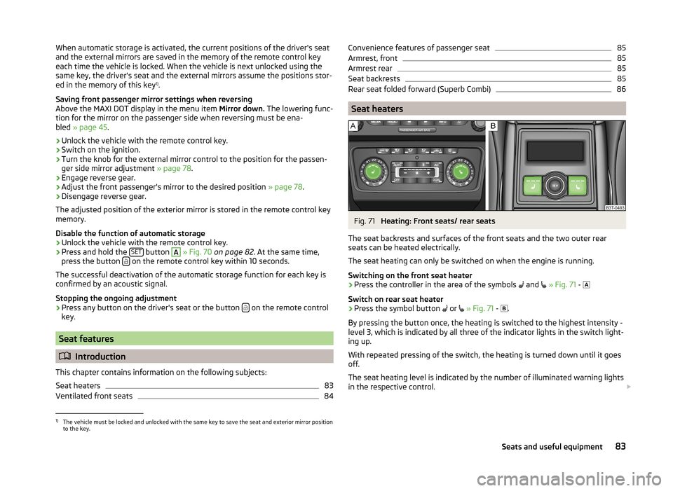
Seat heaters
Fig. 71
Heating: Front seats/ rear seats
The seat backrests and surfaces of the front seats and the two outer rear
seats can be heated electrically.
The seat heating can only be switched on when the engine is running.
Switching on the front seat heater
›
Press the controller in the area of the symbols and
» Fig. 71 -
Switch on rear seat heater
›
Press the symbol button or
» Fig. 71 -
.
By pressing the button once, the heating is switched to the highest intensity -
level 3, which is indicated by all three of the indicator lights in the switch light-
ing up.
With repeated pressing of the switch, the heating is turned down until it goes
off.
The seat heating level is indicated by the number of illuminated warning lights
in the respective control.
1)
The vehicle must be locked and unlocked with the same key to save the seat and exterior mirror position
to the key.
83Seats and useful equipment
Page 91 of 246
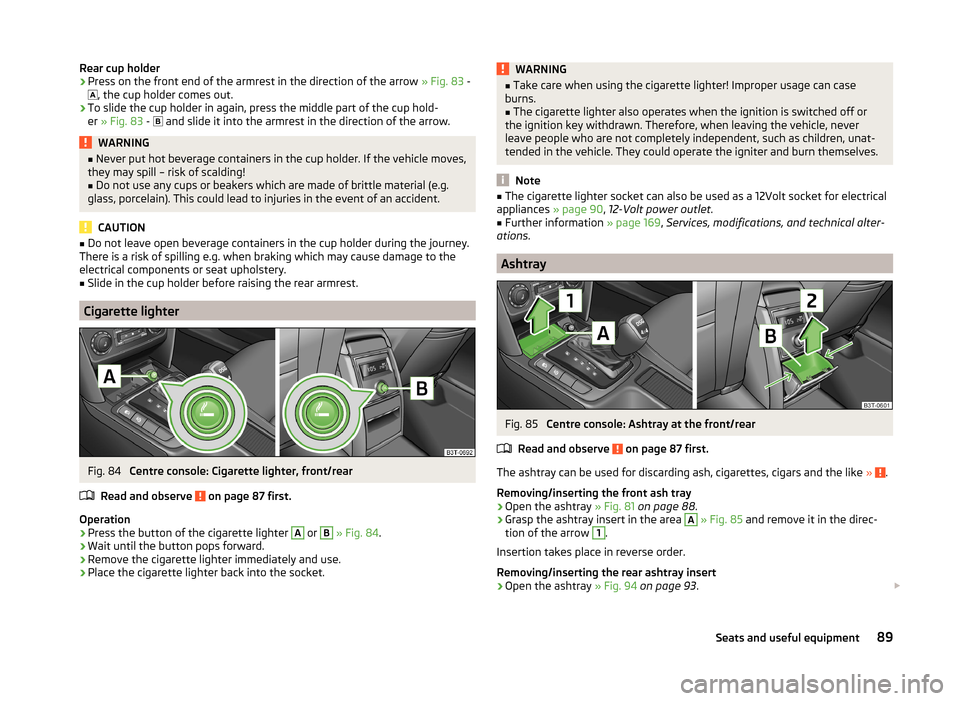
Rear cup holder›Press on the front end of the armrest in the direction of the arrow » Fig. 83 -
, the cup holder comes out.›
To slide the cup holder in again, press the middle part of the cup hold-
er » Fig. 83 -
and slide it into the armrest in the direction of the arrow.
WARNING■
Never put hot beverage containers in the cup holder. If the vehicle moves,
they may spill – risk of scalding!■
Do not use any cups or beakers which are made of brittle material (e.g.
glass, porcelain). This could lead to injuries in the event of an accident.
CAUTION
■ Do not leave open beverage containers in the cup holder during the journey.
There is a risk of spilling e.g. when braking which may cause damage to the
electrical components or seat upholstery.■
Slide in the cup holder before raising the rear armrest.
Cigarette lighter
Fig. 84
Centre console: Cigarette lighter, front/rear
Read and observe
on page 87 first.
Operation
›
Press the button of the cigarette lighter
A
or
B
» Fig. 84 .
›
Wait until the button pops forward.
›
Remove the cigarette lighter immediately and use.
›
Place the cigarette lighter back into the socket.
WARNING■
Take care when using the cigarette lighter! Improper usage can case
burns.■
The cigarette lighter also operates when the ignition is switched off or
the ignition key withdrawn. Therefore, when leaving the vehicle, never
leave people who are not completely independent, such as children, unat-
tended in the vehicle. They could operate the igniter and burn themselves.
Note
■ The cigarette lighter socket can also be used as a 12Volt socket for electrical
appliances » page 90, 12-Volt power outlet .■
Further information » page 169, Services, modifications, and technical alter-
ations .
Ashtray
Fig. 85
Centre console: Ashtray at the front/rear
Read and observe
on page 87 first.
The ashtray can be used for discarding ash, cigarettes, cigars and the like » .
Removing/inserting the front ash tray
›
Open the ashtray » Fig. 81 on page 88 .
›
Grasp the ashtray insert in the area
A
» Fig. 85 and remove it in the direc-
tion of the arrow
1
.
Insertion takes place in reverse order.
Removing/inserting the rear ashtray insert
›
Open the ashtray » Fig. 94 on page 93 .
89Seats and useful equipment
Page 92 of 246
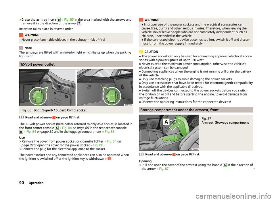
›Grasp the ashtray insert B
» Fig. 85 in the area marked with the arrows and
remove it in the direction of the arrow 2.
Insertion takes place in reverse order.WARNINGNever place flammable objects in the ashtray – risk of fire!
Note
The ashtrays are fitted with an interior light which lights up when the parking
light is on.
12-Volt power outlet
Fig. 86
Boot: Superb / Superb Combi socket
Read and observe
on page 87 first.
The 12-volt power socket (hereinafter referred to only as a socket) is located in
the front center console
A
» Fig. 84 on page 89 in the rear center console
B
» Fig. 84 on page 89 and in the luggage compartment » Fig. 86.
Use
›
Remove the cover from power socket or cigarette lighter » Fig. 84 on
page 89 or open the cover for the power socket » Fig. 86.
›
Connect the plug for the electrical appliance to the socket.
The power socket and any connected appliances can also be operated when
the ignition is switched off or the ignition key is withdrawn »
.
WARNING■
Improper use of the power sockets and the electrical accessories can
cause fires, burns and other serious injuries. Therefore, when leaving the
vehicle, never leave people who are not completely independent, such as
children, unattended in the vehicle.■
If the connected electric device becomes too hot, switch it off and discon-
nect it from the power supply immediately.
CAUTION
■ The power socket can only be used for connecting approved electrical acces-
sories with a power uptake of up to 120 watt.■
Never exceed the maximum power consumption, otherwise the vehicle's
electrical system can be damaged.
■
Connecting appliances when the engine is not running will drain the battery
of the vehicle!
■
Only use matching plugs to avoid damaging the power sockets.
■
Only use accessories that have been tested for electromagnetic compatibility
in accordance with the applicable directives.
■
Switch off the devices connected to the power sockets before you switch
the ignition on or off and before starting the engine, to avoid damage from
voltage fluctuations.
■
Observe the operating instructions for the connected devices!
Storage compartment under the armrest, front
Fig. 87
Armrest: Stowage compartment
Read and observe on page 87 first.
Opening
›
Pull and open the cover of the armrest using the handle
A
in the direction of
the arrow » Fig. 87.
90Operation
Page 125 of 246
If there is no free space available to create a new user profile, delete an exist-
ing user profile.
During the connecting procedure, no other mobile phone may be connected
with the hands-free system.
Up to four mobile phones can be paired with the hands-free system, whereby
only one mobile phone can communicate with the hands-free system.
The visibility of the hands-free system is automatically switched off 3 minutes
after the ignition is switched on and is also deactivated when the mobile
phone has connected to the hands-free system.
Restoring the visibility of the hands-free system
If you have not managed to connect your mobile phone with the hands-free
system within 3 minutes of switching on the ignition, the visibility of the
hands-free system can be reestablished for 3 minutes in the following ways.
› By turning the ignition off and on.
› By turning voice control off and on.
› In the MAXI DOT display under menu item
Bluetooth - Visibility .
Creating a connection with an already paired mobile phone
After switching on the ignition, the connection is automatically established for
the already paired mobile phone 1)
. Check on your mobile phone if the automatic
connection has been established.
Disconnecting the connection
› By withdrawing the ignition key.
› By disconnecting the hands-free system in the mobile phone.
› By disconnecting from the user in the MAXI DOT display under the menu item
Bluetooth - User .
Solving connection problems
If the hands-free system reports No paired phone found, check the operating
status of the mobile phone.
› Is the mobile phone switched on?
› Is the PIN code entered?
› Is Bluetooth ®
active?› Is the visibility of the mobile phone active?
› Has the mobile phone already been paired with the hands-free system?
Telephone operation in the MAXI DOT display
The following menu items can be selected from the Phone menu.
■ Phone book
■ Dial number 2)
■ Call list
■ Voice mailbox
■ Bluetooth 2)
■ Settings 3)
■ Back
Phone book
The Phone book menu item lists the contacts downloaded from the telephone
memory and the mobile phone SIM card.
Dial number
Any telephone number can be entered in the Dial number menu item. The re-
quired digits must be selected one after the other using the adjustment wheel,
and then confirmed by pressing the adjustment wheel. You can select digits
0-9 , symbols
,
, #
and the Cancel, Call and Delete functions.
Call list
The following menu items can be selected in the Call list menu item.
■ Missed calls - List of missed calls
■ Dialled Nos. - List of dialled numbers
■ Received calls - list of received calls
Voice mailbox
In the Voice mailbox menu item, you can set the number of the voice mailbox 2)
and then dial the number.
1)
Some mobile phones have a menu, in which the authorisation for establishing a Bluetooth®
connection
is completed by inputting a code. If the authorisation input is required, it must always be performed
when re-establishing the Bluetooth connection.
2)
On vehicles fitted with the Amundsen+ navigation system, this function can be accessed via the naviga-
tion system menu; refer to the » operating instructions for the Amundsen+ navigation system .
3)
This function is not available in vehicles fitted with the Amundsen+ navigation system.
123Communication and multimedia
Page 127 of 246
›Select the phone you wish to connect from the list of units found.›Confirm the PIN 1)
.›
If your SIM card is blocked by a PIN code, enter the PIN code for the SIM card
in your phone. The telephone connects to the hands-free system (during the
first connection you can only enter the PIN code in the MAXI DOT display when the vehicle is stationary, as this is the only situation when you can
choose whether the PIN code should be stored).
›
To save a new user, follow the instructions in the Maxi DOT display.
›
Reconfirm the rSAP command on your mobile phone to download the tele-
phone book and the identification data from the SIM card into the hands-free
system.
Connecting the telephone with the hands-free system via the HPP profile
›
Activate Bluetooth ®
and the visibility of your mobile phone on your tele-
phone.
›
Switch on the ignition.
›
Select the Phone - New user menu in the MAXI DOT display and wait until
the hands-free system has completed the search.
›
Select the phone you wish to connect from the list of units found.
›
Confirm the PIN 1 )
.
›
Follow the instructions on the MAXI DOT display and the mobile phone to
store a new user or to download the telephone book and identification data
from the SIM card into the hands-free system.
The telephone primarily connects via the rSAP profile.
If the PIN code was stored, the telephone is automatically detected and con- nected with the hands-free system the next time the ignition is switched on.
Check your mobile phone to see whether this automatic connection has been
established.
Disconnecting the connection
› By removing the key from the ignition lock (the connection is disconnected
during a telephone call).
› By disconnecting the hands-free system in the mobile phone.
› Select the user by disconnecting the user in the Maxi DOT display in the
Bluetooth - User menu option - Disconnect.
On vehicles which are fitted with a radio or navigation system at the factory, it
is possible to terminate the telephone call after removing the key from the ig-
nition lock by pressing the button on the touch screen of the radio 2)
or naviga-
tion system; refer to the » Operating instructions for the radio or navigation
system .
Note
■
In the memory of the hands-free system, up to three users can be stored,
whereby the hands-free system can only communicate actively with one user.
If a connection is established with a fourth mobile phone, one of the users
must be deleted.■
When connecting to the hands-free system, follow the instructions on your
mobile phone.
Telephone operation in the MAXI DOT display
If no phone is connected to the hands-free system, the message No paired
phone found appears along with the following menu items when the Mobile
phone menu is selected.
■ Help - This menu item appears when no paired phone is stored in the memo-
ry of the hands-free system.
■ Connect - This menu item appears when one or more paired phones are stor-
ed in the memory of the hands-free system.
■ New user - New phone
■ Media player - Media player
■ Active device - Connected device
■ Paired devices - List of paired devices
■ Search - Device search
■ Visibility - Visibility on/off
■ SOS - Emergency call
If a telephone is paired with the hands-free system, the following menu items
can be selected in the Mobile phone menu.
Phone book
The Phone book menu item lists the contacts downloaded from the telephone
memory and the mobile phone SIM card.
1)
Depending on the Bluetooth®
version on the mobile phone, an automatically generated 6-digit PIN (SSP)
will either be displayed, or a 16-digit code displayed in the MAXI DOTdisplay will need to be entered into
your mobile phone and confirmed within 30 seconds by following the instructions on your mobile phone
display.
2)
Does not apply for Radio Swing.
125Communication and multimedia
Page 137 of 246
Driving
Starting-off and Driving
Starting and stopping the engine using the key
Introduction
This chapter contains information on the following subjects:
Electronic immobilizer
136
Ignition Switch
136
Starting the engine
136
Stopping the engine
137
Starting and stopping the engine on vehicles with the KESSY sys-
tem » page 137 .
The engine can only be started using a correctly coded original key.
The engine running noises may louder at first be louder for a short time after
starting the cold engine. This is quite normal and is not an operating problem.
WARNING■ When the vehicle is travelling with the engine off, the ignition key must
always be in position 2 » Fig. 133 on page 136 (ignition switched on). This
position is confirmed by the appearance of certain indicator lamps in the in-
strument cluster. ■If the key is not in position 2,
it could unexpectedly lock the steering -
danger of accident!
■
Only pull the ignition key from the ignition lock when the vehicle has
come to a complete stop (by applying the handbrake). Otherwise, the steer-
ing could be blocked – risk of accident!
■
Never leave the key in the vehicle when you exit the vehicle. Unauthor-
ized persons, such as children, for example, could lock the car, turn on the
ignition or start the engine - there is a danger of injury and accidents!
■
Never leave the vehicle unattended with the engine running - there is
risk of accident, damage or theft!
■
Never switch off the engine before the vehicle is stationary – risk of acci-
dent!
WARNING■ Never leave the engine running in unventilated or closed rooms. The ex-
haust gases from the engine contain substances such as odourless and col-
ourless carbon monoxide (a poisonous gas) – risk to life! ■Carbon monoxide can cause unconsciousness and death.■
Do not leave any items (e.g. cloths or tools) in the engine compartment.
This presents a fire hazard and the risk of engine damage.
■
Never cover the engine with additional insulation material (e.g. with a
cover) – risk of fire!
CAUTION
■ The starter must only be operated when the engine is not running and the
vehicle is at a standstill. The starter or engine can be damaged if the starter is
activated when the engine is running 3
» Fig. 133 on page 136 .
■
Do not tow start the engine – there is a risk of damaging the engine and the
catalytic converter. The battery from another vehicle can be used as a jump-
start aid » page 207 , Jump-starting .
CAUTION
■
Avoid high engine revolutions, full throttle and high engine loads before the
engine has reached its operating temperature – risk of damaging the engine!■
Do not switch the engine off immediately at the end of your journey after the
engine has been operated over a prolonged period at high loads but leave it to
run at an idling speed for about 1 minute. This prevents any possible accumula-
tion of heat when the engine is switched off.
For the sake of the environment
Do not warm up the engine while the vehicle is stationary. If possible, start
your journey as soon as the engine has started. Through this the engine rea-
ches its operating temperature more rapidly and the pollutant emissions are
lower.
Note
After switching off the ignition, the radiator fan may intermittently continue to
operate for approx. 10 minutes.135Starting-off and Driving