fuel pump SKODA SUPERB 2014 2.G / (B6/3T) Owner's Manual
[x] Cancel search | Manufacturer: SKODA, Model Year: 2014, Model line: SUPERB, Model: SKODA SUPERB 2014 2.G / (B6/3T)Pages: 246, PDF Size: 17.16 MB
Page 119 of 246
WARNING■The auxiliary heating (aux. heating) must never be operated in closed
rooms (e.g. garages) – risk of poisoning!■
The auxiliary heating (aux. heating) must not be allowed to run during re-
fuelling – risk of fire.
■
The exhaust pipe of the auxiliary heating (aux. heating) is located on the
underside of the vehicle. Therefore, if you wish to operate the auxiliary
heating (aux. heating), do not park the vehicle in such a way that the ex-
haust gases can come into contact with highly flammable materials (e.g. dry
grass) or easily inflammable substances (e.g. spilt fuel) – risk of fire.
CAUTION
■ Running auxiliary heating (aux. heating) consumes fuel from the vehicle tank
and automatically controls the filling level. If only a low quantity of fuel is
present in the fuel tank, the auxiliary heating (aux. heating) switches off.■
The exhaust pipe of the auxiliary heating (aux. heating), which is located on
the underside of the vehicle, must not be clogged and the exhaust flow must
not be blocked.
■
If the auxiliary heating (aux. heating) is running, the vehicle battery discharg-
es. If the auxiliary heating and ventilation has been operated several times
over a longer period, the vehicle must be driven a few kilometres in order to
recharge the vehicle battery.
Note
■ The auxiliary heating (aux. heating) switches on the blower B » Fig. 124 on
page 110 or » Fig. 125 on page 113 only if it has achieved a coolant temperature
of approx. 50 °C.■
At low outside temperatures, this can result in a formation of water vapour in
the area of the engine compartment. This is quite normal and is not an operat-
ing problem.
■
The air inlet in front of the windscreen must be free (e.g. of ice, snow or
leaves) to ensure that the auxiliary heating (aux. heating) operates properly.
■
So that warm air can flow into the vehicle interior after switching on the aux-
iliary heating, you must maintain the comfort temperature normally selected
by you, leave the fan switched on and leave the air outlet vents in an open po-
sition. It is recommended to put the air flow in the position
or
.
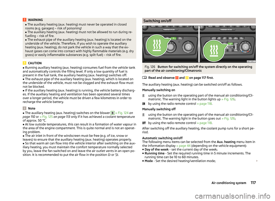
Switching on/offFig. 126
Button for switching on/off the system directly on the operating
part of the air conditioning/Climatronic
Read and observe
and on page 117 first.
The auxiliary heating (aux. heating) can be switched on/off as follows.
Manually switching on using the button on the operating part of the manual air conditioning/Cli-
matronic. The warning light in the button lights up » Fig. 126;
by using the radio remote control » page 118.
Manually switching off using the button on the operating part of the manual air conditioning/Cli-
matronic. The warning light in the button goes out » Fig. 126;
by using the radio remote control » page 118.
After switching off the auxiliary heating, the coolant pump runs for a short pe-
riod.
Automatic switching on/off
The following menu items can be selected from the Aux. heating menu item in
the information display » page 44 (depending on the vehicle equipment):
■ Day of the week - set the current day of the week;
■ Running time - Set the required running time in 5 minute increments. The
running time can be 10 to 60 minutes.
■ Mode - Set the desired heating/ventilation mode;
117Air conditioning system
Page 139 of 246
Vehicles with automatic transmission1)
The engine will not start if the brake pedal is not depressed.
The following message is shown in the information cluster display. Depress brake to start!
BRAKE
CAUTION
■ If the engine does not start up after a second attempt, one of the following
fuses may be defective. ■ Petrol engine - fuse for the electric fuel pump.
■ Diesel engine - fuse for the control unit for glow plugs or glow plug relay
and fuel pump.■
Check the fuse and replace if necessary » page 215, or seek assistance from
a specialist garage.
Stopping the engine
Read and observe
and on page 135 first.
Switch off the engine by turning the ignition key to position
1
» Fig. 133 on
page 136 .
For vehicles with automatic transmission, the ignition key can only be removed
if the selector lever is in position P.
Starting and stopping the engine - KESSY
Introduction
This chapter contains information on the following subjects:
Steering lock / unlock
138
Ignition on/off
138
Starting the engine
139
Switching off the engine
139
Emergency start-up of the engine
139
Emergency ignition shutoff system
140The KESSY system (Keyless Entry Exit System, hereinafter referred to only as
system) allows the switching on or switching off of the ignition and starting or
stopping of the engine without the active use of the key.
A key must be in the vehicle to unlock the steering, switch on the ignition and
start the vehicle. When travelling the key must be in the vehicle.
The engine running noises may louder at first be louder for a short time after starting the cold engine. This is quite normal and is not an operating problem.WARNING■ Never leave the key in the vehicle when you exit the vehicle. Unauthor-
ized persons, such as children, for example, could lock the car, turn on the
ignition or start the engine - there is a danger of injury and accidents!■
Never leave the vehicle unattended with the engine running - there is a
risk of theft etc!
■
Never switch off the engine before the vehicle is stationary – risk of acci-
dent!
WARNING■ Never leave the engine running in unventilated or closed rooms. The ex-
haust gases from the engine contain substances such as odourless and col-
ourless carbon monoxide (a poisonous gas) – risk to life! ■Carbon monoxide can cause unconsciousness and death.
CAUTION
■ The system can recognize the valid key, even if it has been forgotten, for ex-
ample, in the front of the vehicle roof D » Fig. 32 on page 50 - There is danger
of loss or damage to the key! It is therefore not always necessary to know
where the key is.■
The starter must only be operated when the engine is not running and the
vehicle is at a standstill. The starter or engine may be damaged if the starter is
activated when the engine is running.
■
Do not tow start the engine – there is a risk of damaging the engine and the
catalytic converter. The battery from another vehicle can be used as a jump-
start aid » page 207 , Jump-starting .
1)
Applies to vehicles with START-STOP system.
137Starting-off and Driving
Page 141 of 246
If the driver's door is opened while the igition is on, an audible signal sounds
and the following message appears in the instrument cluster display.
Ignition on!
IGNITION ON
When leaving the vehicle always switch off the ignition.
Note
The ignition is switched on when indicated by the lighting up of certain indica-
tor lamps in the instrument cluster.
Starting the engine
Read and observe
and on page 137 first.
Vehicles with a diesel engine are equipped with a glow plug system. The glow
plug warning light lights up after the ignition has been switched on. Start
the engine once the warning light has gone out.
You should not switch on any major electrical components during the heating
period otherwise the vehicle battery will be drained unnecessarily.
Procedure for starting the engine
›
Firmly apply the handbrake.
›
Move the gearshift lever into neutral or move the selector lever into position
P or N.
›
Depress and hold the clutch pedal (vehicles with a manual gearbox) or brake
pedal (vehicles with an automatic gearbox) until the engine starts.
›
Press and hold » Fig. 134 on page 138 1)
the starter button until the engine
starts.
CAUTION
■ If the engine does not start up after a second attempt, one of the following
fuses may be defective. ■ Petrol engine - fuse for the electric fuel pump.
■ Diesel engine - fuse for the control unit for glow plugs or glow plug relay
and fuel pump.■
Check the fuse and replace if necessary » page 215, or seek assistance from
a specialist garage.
Switching off the engine
Read and observe
and on page 137 first.
›
Stop the vehicle.
›
Press the starter button » Fig. 134 on page 138 briefly.
The engine and the ignition are switched off simultaneously.
The engine can be switched off up to a speed of 2 km/h.
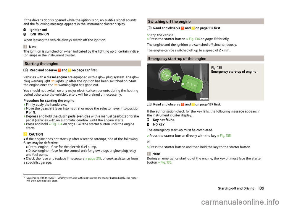
Emergency start-up of the engine
Fig. 135
Emergency start-up of engine
Read and observe and on page 137 first.
If the authorisation check for the key fails, the following message appears in
the instrument cluster display.
Key not found.
NO KEY
The emergency start-up must be completed.
› Press the starter button directly with the key
» Fig. 135.
or
› Press the starter button and then hold the key to the starter button.
Note
During an emergency start-up of the engine, the key bit must face the starter
button » Fig. 135 .1)
On vehicles with the START-STOP system, it is sufficient to press the starter button briefly. The motor
will then automatically start.
139Starting-off and Driving
Page 182 of 246
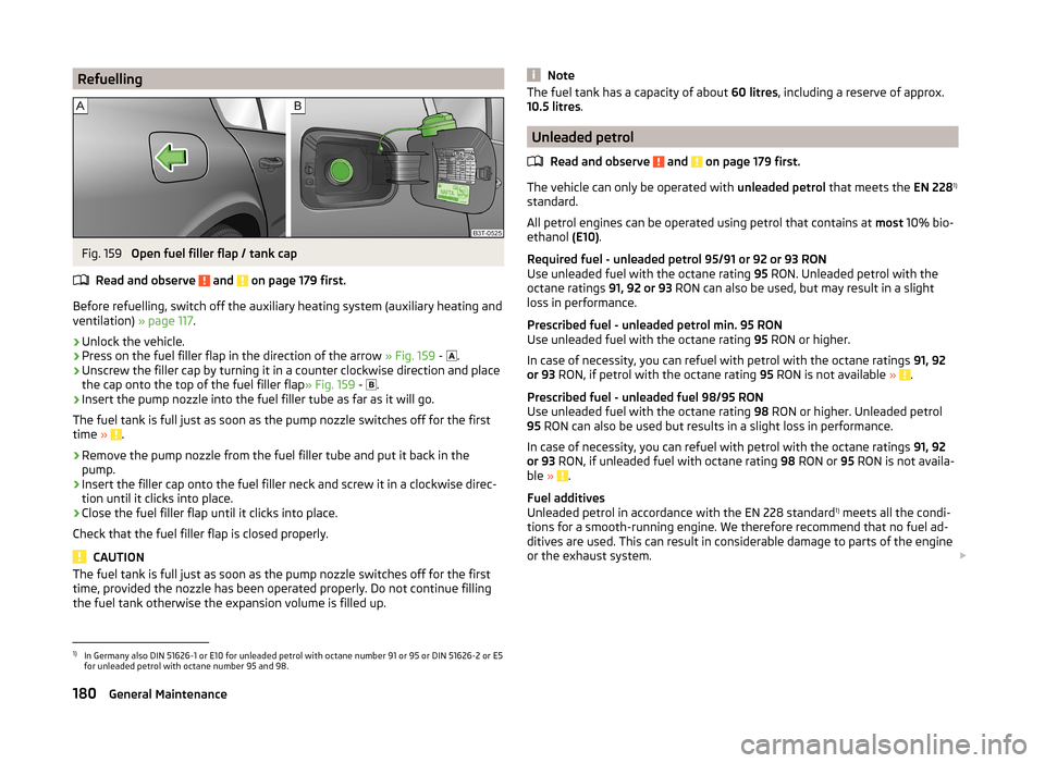
RefuellingFig. 159
Open fuel filler flap / tank cap
Read and observe
and on page 179 first.
Before refuelling, switch off the auxiliary heating system (auxiliary heating and ventilation) » page 117.
›
Unlock the vehicle.
›
Press on the fuel filler flap in the direction of the arrow » Fig. 159 -
.
›
Unscrew the filler cap by turning it in a counter clockwise direction and place
the cap onto the top of the fuel filler flap » Fig. 159 -
.
›
Insert the pump nozzle into the fuel filler tube as far as it will go.
The fuel tank is full just as soon as the pump nozzle switches off for the first
time »
.
›
Remove the pump nozzle from the fuel filler tube and put it back in the
pump.
›
Insert the filler cap onto the fuel filler neck and screw it in a clockwise direc-
tion until it clicks into place.
›
Close the fuel filler flap until it clicks into place.
Check that the fuel filler flap is closed properly.
CAUTION
The fuel tank is full just as soon as the pump nozzle switches off for the first
time, provided the nozzle has been operated properly. Do not continue filling
the fuel tank otherwise the expansion volume is filled up.NoteThe fuel tank has a capacity of about 60 litres, including a reserve of approx.
10.5 litres .
Unleaded petrol
Read and observe
and on page 179 first.
The vehicle can only be operated with unleaded petrol that meets the EN 2281)
standard.
All petrol engines can be operated using petrol that contains at most 10% bio-
ethanol (E10).
Required fuel - unleaded petrol 95/91 or 92 or 93 RON
Use unleaded fuel with the octane rating 95 RON. Unleaded petrol with the
octane ratings 91, 92 or 93 RON can also be used, but may result in a slight
loss in performance.
Prescribed fuel - unleaded petrol min. 95 RON
Use unleaded fuel with the octane rating 95 RON or higher.
In case of necessity, you can refuel with petrol with the octane ratings 91, 92
or 93 RON, if petrol with the octane rating 95 RON is not available »
.
Prescribed fuel - unleaded fuel 98/95 RON
Use unleaded fuel with the octane rating 98 RON or higher. Unleaded petrol
95 RON can also be used but results in a slight loss in performance.
In case of necessity, you can refuel with petrol with the octane ratings 91, 92
or 93 RON, if unleaded fuel with octane rating 98 RON or 95 RON is not availa-
ble »
.
Fuel additives
Unleaded petrol in accordance with the EN 228 standard 1)
meets all the condi-
tions for a smooth-running engine. We therefore recommend that no fuel ad-
ditives are used. This can result in considerable damage to parts of the engine
or the exhaust system.
1)
In Germany also DIN 51626-1 or E10 for unleaded petrol with octane number 91 or 95 or DIN 51626-2 or E5
for unleaded petrol with octane number 95 and 98.
180General Maintenance
Page 218 of 246
CAUTION■“Never repair” fuses or replace them with a fuse of a higher amperage – risk
of fire! This may also cause damage at another part of the electrical system.■
If a newly inserted fuse blows again after a short time, have the electrical
system checked as quickly as possible by a specialist garage.
■
A blown fuses is recognisable by the molten metal strip. Replace the faulty
fuse with a new one of the same amperage.
Note
■
We recommend always carrying replacement fuses in the vehicle. A box of
replacement fuses can be purchased from ŠKODA Original Accessories.■
There can be several power consuming devices for one fuse.
■
Multiple fuses may exist for a single power consuming device.
Fuses in the dash panel
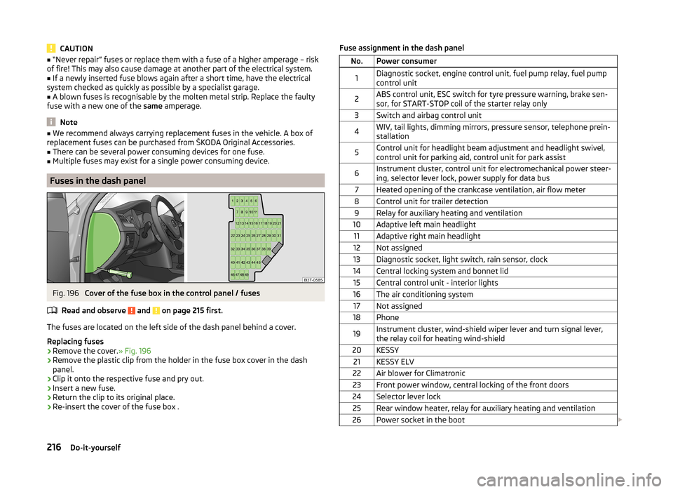
Fig. 196
Cover of the fuse box in the control panel / fuses
Read and observe
and on page 215 first.
The fuses are located on the left side of the dash panel behind a cover.
Replacing fuses
›
Remove the cover. » Fig. 196
›
Remove the plastic clip from the holder in the fuse box cover in the dash
panel.
›
Clip it onto the respective fuse and pry out.
›
Insert a new fuse.
›
Return the clip to its original place.
›
Re-insert the cover of the fuse box .
Fuse assignment in the dash panelNo.Power consumer1Diagnostic socket, engine control unit, fuel pump relay, fuel pump
control unit2ABS control unit, ESC switch for tyre pressure warning, brake sen-
sor, for START-STOP coil of the starter relay only3Switch and airbag control unit4WIV, tail lights, dimming mirrors, pressure sensor, telephone prein-
stallation5Control unit for headlight beam adjustment and headlight swivel,
control unit for parking aid, control unit for park assist6Instrument cluster, control unit for electromechanical power steer-
ing, selector lever lock, power supply for data bus7Heated opening of the crankcase ventilation, air flow meter8Control unit for trailer detection9Relay for auxiliary heating and ventilation10Adaptive left main headlight11Adaptive right main headlight12Not assigned13Diagnostic socket, light switch, rain sensor, clock14Central locking system and bonnet lid15Central control unit - interior lights16The air conditioning system17Not assigned18Phone19Instrument cluster, wind-shield wiper lever and turn signal lever,
the relay coil for heating wind-shield20KESSY21KESSY ELV22Air blower for Climatronic23Front power window, central locking of the front doors24Selector lever lock25Rear window heater, relay for auxiliary heating and ventilation26Power socket in the boot 216Do-it-yourself
Page 219 of 246
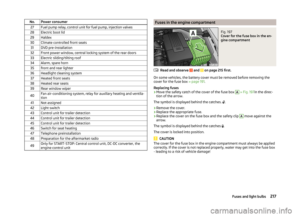
No.Power consumer27Fuel pump relay, control unit for fuel pump, injection valves28Electric boot lid29Haldex30Climate controlled front seats31DVD pre-installation32Front power window, central locking system of the rear doors33Electric sliding/tilting roof34Alarm, spare horn35front and rear lighter36Headlight cleaning system37Heated front seats38Heated rear seats39Rear window wiper40Fan air-conditioning system, relay for auxiliary heating and ventila-
tion41Not assigned42Light switch43Control unit for trailer detection44Control unit for trailer detection45Control unit for trailer detection46Switch for seat heating47Telephone preinstallation48Preparation for the aftermarket radio49Only for START-STOP: Central control unit, DC-DC converter, the
engine control unitFuses in the engine compartmentFig. 197
Cover for the fuse box in the en-
gine compartment
Read and observe and on page 215 first.
On some vehicles, the battery cover must be removed before removing the
cover for the fuse box » page 191.
Replacing fuses
›
Move the safety catch of the cover of the fuse box
A
» Fig. 197 in the direc-
tion of the arrow.
The symbol is displayed behind the catches. .
›
Remove the cover.
›
Replace the appropriate fuse.
›
Replace the cover on the fuse box and the safety clip
A
move against the
arrow.
The symbol is displayed behind the catches .
The cover is locked into position.
CAUTION
The cover for the fuse box in the engine compartment must always be applied
correctly. If the cover is not replaced properly, water may get into the fuse box
- leading to a risk of vehicle damage!217Fuses and light bulbs
Page 220 of 246
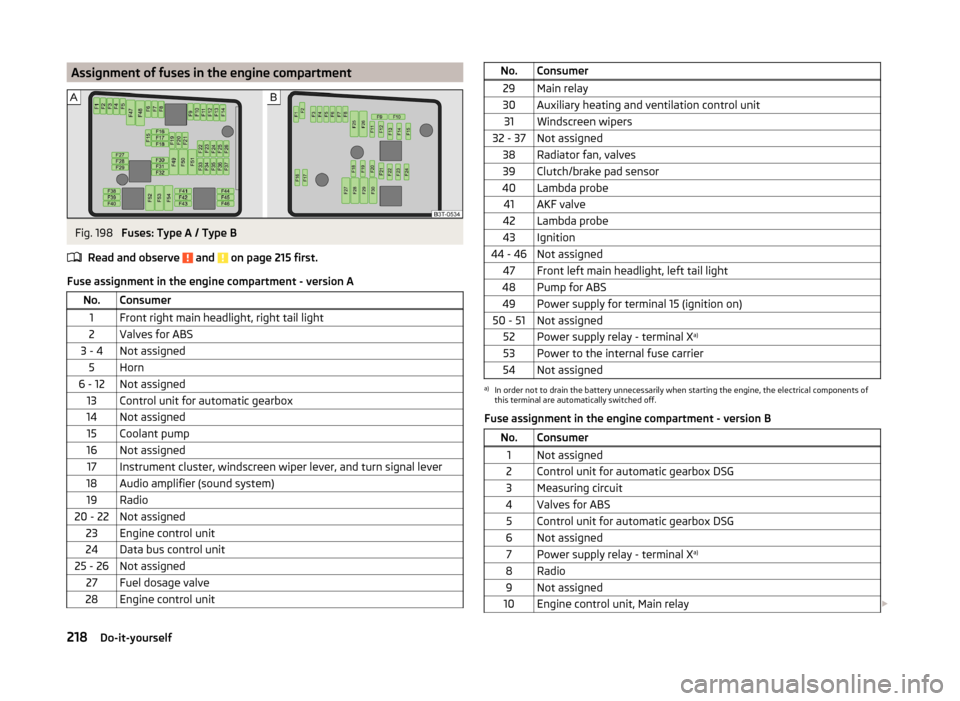
Assignment of fuses in the engine compartmentFig. 198
Fuses: Type A / Type B
Read and observe
and on page 215 first.
Fuse assignment in the engine compartment - version A
No.Consumer1Front right main headlight, right tail light2Valves for ABS3 - 4Not assigned5Horn6 - 12Not assigned13Control unit for automatic gearbox14Not assigned15Coolant pump16Not assigned17Instrument cluster, windscreen wiper lever, and turn signal lever18Audio amplifier (sound system)19Radio20 - 22Not assigned23Engine control unit24Data bus control unit25 - 26Not assigned27Fuel dosage valve28Engine control unitNo.Consumer29Main relay30Auxiliary heating and ventilation control unit31Windscreen wipers32 - 37Not assigned38Radiator fan, valves39Clutch/brake pad sensor40Lambda probe41AKF valve42Lambda probe43Ignition44 - 46Not assigned47Front left main headlight, left tail light48Pump for ABS49Power supply for terminal 15 (ignition on)50 - 51Not assigned52Power supply relay - terminal X a)53Power to the internal fuse carrier54Not assigneda)
In order not to drain the battery unnecessarily when starting the engine, the electrical components of
this terminal are automatically switched off.
Fuse assignment in the engine compartment - version B
No.Consumer1Not assigned2Control unit for automatic gearbox DSG3Measuring circuit4Valves for ABS5Control unit for automatic gearbox DSG6Not assigned7Power supply relay - terminal X a)8Radio9Not assigned10Engine control unit, Main relay
218Do-it-yourself
Page 221 of 246
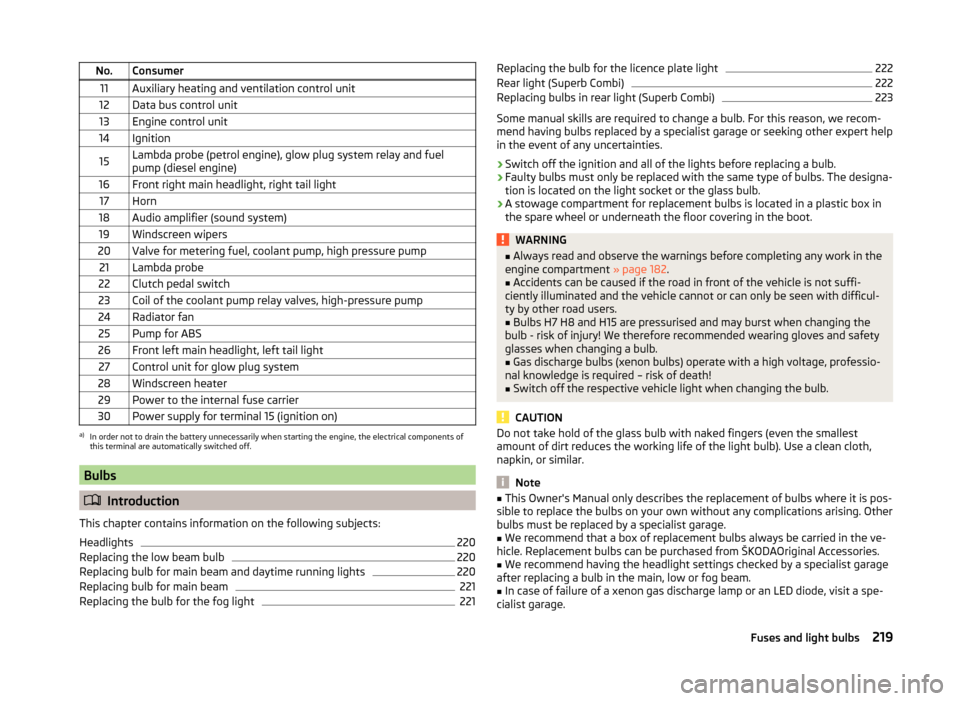
No.Consumer11Auxiliary heating and ventilation control unit12Data bus control unit13Engine control unit14Ignition15Lambda probe (petrol engine), glow plug system relay and fuel
pump (diesel engine)16Front right main headlight, right tail light17Horn18Audio amplifier (sound system)19Windscreen wipers20Valve for metering fuel, coolant pump, high pressure pump21Lambda probe22Clutch pedal switch23Coil of the coolant pump relay valves, high-pressure pump24Radiator fan25Pump for ABS26Front left main headlight, left tail light27Control unit for glow plug system28Windscreen heater29Power to the internal fuse carrier30Power supply for terminal 15 (ignition on)a)
In order not to drain the battery unnecessarily when starting the engine, the electrical components of
this terminal are automatically switched off.
Bulbs
Introduction
This chapter contains information on the following subjects:
Headlights
220
Replacing the low beam bulb
220
Replacing bulb for main beam and daytime running lights
220
Replacing bulb for main beam
221
Replacing the bulb for the fog light
221Replacing the bulb for the licence plate light222Rear light (Superb Combi)222
Replacing bulbs in rear light (Superb Combi)
223
Some manual skills are required to change a bulb. For this reason, we recom-
mend having bulbs replaced by a specialist garage or seeking other expert help
in the event of any uncertainties.
› Switch off the ignition and all of the lights before replacing a bulb.
› Faulty bulbs must only be replaced with the same type of bulbs. The designa-
tion is located on the light socket or the glass bulb.
› A stowage compartment for replacement bulbs is located in a plastic box in
the spare wheel or underneath the floor covering in the boot.
WARNING■ Always read and observe the warnings before completing any work in the
engine compartment » page 182.■
Accidents can be caused if the road in front of the vehicle is not suffi-
ciently illuminated and the vehicle cannot or can only be seen with difficul-
ty by other road users.
■
Bulbs H7 H8 and H15 are pressurised and may burst when changing the
bulb - risk of injury! We therefore recommended wearing gloves and safety
glasses when changing a bulb.
■
Gas discharge bulbs (xenon bulbs) operate with a high voltage, professio-
nal knowledge is required – risk of death!
■
Switch off the respective vehicle light when changing the bulb.
CAUTION
Do not take hold of the glass bulb with naked fingers (even the smallest
amount of dirt reduces the working life of the light bulb). Use a clean cloth,
napkin, or similar.
Note
■ This Owner's Manual only describes the replacement of bulbs where it is pos-
sible to replace the bulbs on your own without any complications arising. Other
bulbs must be replaced by a specialist garage.■
We recommend that a box of replacement bulbs always be carried in the ve-
hicle. Replacement bulbs can be purchased from ŠKODAOriginal Accessories.
■
We recommend having the headlight settings checked by a specialist garage
after replacing a bulb in the main, low or fog beam.
■
In case of failure of a xenon gas discharge lamp or an LED diode, visit a spe-
cialist garage.
219Fuses and light bulbs