change time SKODA SUPERB 2015 3.G / (B8/3V) User Guide
[x] Cancel search | Manufacturer: SKODA, Model Year: 2015, Model line: SUPERB, Model: SKODA SUPERB 2015 3.G / (B8/3V)Pages: 276, PDF Size: 42.14 MB
Page 168 of 276
Start controlRead and observe
on page 163 first.
Basic requirements for start of control The ACC is activated.
The TCS is activated » page 143, Braking and stabilisation systems .
On vehicles with a manual transmission , the second gear or higher must
be engaged.
On vehicles with an automatic transmission , the selector lever must be in
the D/S position or in the Tiptronic position.
On vehicles with a manual transmission , the current speed must be higher
than approx. 25 km/h.
The control be started with the key or by adjusting the lever
» Fig. 204 on page 165 into the sprung position.
Button
›
Press the button .
The ACC will adopt the current speed and execute control.
Lever position
›
Set the lever into the sprung position Set.
The ACC will adopt the current speed and execute control. Should the speed be stored already, the ACC adopts this speed and executes control.
The warning light illuminates in the instrument cluster when the regulation
is switched on.
Note
■ If control is started at a speed of less than 30 km/h on vehicles with an auto-
matic transmission, the speed of 30 km/h is stored. The speed increases auto-
matically to 30 km/h or is regulated with respect to the speed of the vehicle
ahead.■
When TCS is disabled, it will be activated automatically upon starting control.
■
If the TCS is deactivated during control, control is stopped automatically.
Stop/resume control
Read and observe
on page 163 first.
Stop control
›
Set the lever into the sprung position
» Fig. 204 on page 165 Set.
Or
›
Apply the brake.
Control stops, the speed remains stored.
Resume control
›
Start control » page 166.
WARNINGControl may only be resumed if the stored speed is not too high for the cur-
rent traffic conditions.
Note
Regulation is also stopped when the clutch is held down for longer than 30 s.
Set/change the desired speed
Read and observe
on page 163 first.
The desired speed can be set or changed using the control lever » Fig. 204 on
page 165 .
The set speed is stored upon releasing the lever or the button on the button
on the lever.
Setting/changing the speed by 10 km/h at a time (
) - requirements
The ACC is activated.
Increasing the speed by 1 km/h at a time (
) - requirements
The ACC is activated.
The vehicle is controlled.
Decreasing the speed by 1 km/h at a time (
) - requirements
The ACC is activated.
The vehicle is controlled.
166Driving
Page 169 of 276
Changing the speed by adopting the current speed () - requirements
The ACC is activated.
The vehicle is moving at a speed other than that which is stored.
Note
■
If during control the speed is increased by pressing the accelerator, control is
temporarily stopped. Upon releasing the accelerator, control is automatically
resumed.■
If during control the speed is reduced by applying the brake, control is stop-
ped. Control needs to be restarted in order to resume » page 166.
■
If the vehicle is controlled by a lower speed than the stored speed, then
the current speed is stored the first time the key is pressed. Press the key
again
and the speed is reduced in increments of 1 km/h.
Set the clearance level
Read and observe
on page 163 first.
The proximity to the vehicle ahead can be set with the lever » Fig. 204 on
page 165 or in the Infotainment » Owner´s Manual Infotainment , chapter CAR -
Vehicle settings .
Setting by means of the lever
›
Set the switch to the spring-loaded position or to -
» Fig. 204 on
page 165 .
The display of the instrument cluster shows line
2
» Fig. 202 on page 164 ,
which indicates the proximity.
›
Using the switch set line
2
on the lever to the desired distance level.
Note
■
If the proximity is changed in infotainment, the change will only come into
effect after a subsequent activation of the ACC.■
The proximity is dependent on the speed. The higher the speed, the greater
the proximity to the vehicle ahead.
■
On wet roads, a longer time interval to the vehicle ahead should always be
selected than on dry roads.
Special driving conditionsFig. 205
Special conditions: Cornering / narrow vehicles or vehicles trav-
elling side by side
Fig. 206
Special conditions: Lane changes of other vehicles / stationary
vehicles
Read and observe
on page 163 first.
The following and similar situations require special attention of the driver.
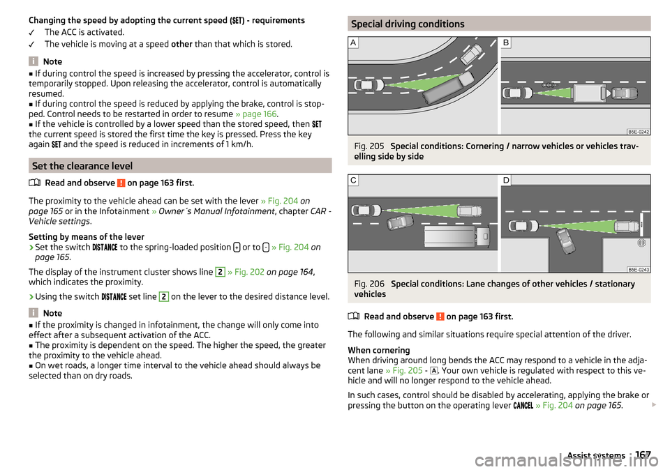
When cornering
When driving around long bends the ACC may respond to a vehicle in the adja-
cent lane » Fig. 205 -
. Your own vehicle is regulated with respect to this ve-
hicle and will no longer respond to the vehicle ahead.
In such cases, control should be disabled by accelerating, applying the brake or
pressing the button on the operating lever
» Fig. 204 on page 165 .
167Assist systems
Page 170 of 276
Narrow vehicles or vehicles travelling side by side
Narrow vehicles or vehicles travelling side by side are not detected by the ra-
dar sensor until they are within the sensor's range » Fig. 205 -
.
If necessary, slow down the car by applying the brake.
Other vehicles changing lanes
Vehicles that change onto the lane with a small proximity » Fig. 206 -
do not
have to be detected by the radar sensor in time. The result may be a delayed
ACC response.
If necessary, slow down the car by applying the brake.
Stationary vehicles
The ACC does not detect stationary objects! When a vehicle detected by the
ACC turns or sheers off and there is a stationary vehicle in front of this vehicle,
» Fig. 206 -
the ACC does not respond to the stationary vehicle.
In such cases, take over the steering and stop the vehicle by applying the foot
brake.
When overtaking
When your vehicle is being controlled (the speed is lower than that which is
stored) and the indicator is activated, the ACC interprets this situation as
meaning that the driver intends to overtake. The ACC automatically acceler-
ates the vehicle, thereby reducing the proximity to a vehicle ahead.
If the vehicle changes to the fast lane and no vehicle is detected ahead, the
ACC accelerates until the set speed is reached and then keeps it constant.
Acceleration can be cancelled at any time by touch on the brake pedal or
pressing the button on the lever
» Fig. 204 on page 165 .
Vehicles with special load or special body parts
Other vehicles with a load or with body parts protruding from the sides, back
or top of the vehicle contour may not be detected by the ACC.
Control should therefore be disabled whenever you are driving behind or over-
taking such a vehicle.
Towing a trailer
When towing, or in when another accessory is connected to the trailer socket
the ACC control is set with a lower rate. The manner of driving should there-
fore be adapted to this limitation.Information messages
Read and observe
on page 163 first.
The warning symbols are shown in the instrument cluster display.
ACC: no sensor view!
The sensor cover or the sensor is covered or dirty.
Stop the car, switch off the engine and clean the sensor cover or remove the
obstacle » Fig. 174 on page 143 .
If this message appears in winter, the cause can be snow covering the sensor.
The ACC is functional again after the snow melts away from the sensor.
If the message appears again after starting the engine, the position of the lev- er should be
» Fig. 204 on page 165 adjusted.
ACC not available.
The ACC is not available for an unknown reason.
Stop the vehicle, switch off the engine and then start it again. If the ACC is still
not available, push the lever into position . Seek help from a specialist ga-
rage.
Error: ACC
There is an ACC system error.
Push the lever into position / press. Seek help from a specialist garage.
Speed limit
Increase the speed accordingly and start control
» page 166.
Front Assist
Introduction
This chapter contains information on the following subjects:
Operation
169
Distance warning (dangerous distance)
169
Warning and automatic braking
169
Disable/enable
170
Information messages
171
168Driving
Page 179 of 276
Assistant for “blind spot monitoring”
Introduction
This chapter contains information on the following subjects:
Operation
177
Driving conditions and warnings
178
Activation / deactivation
178
Information messages
179
The assistant for“blind spot monitoring” (following known as system) draws
attention to vehicles travelling in the same direction in the next lane in the so
called blind spots.
The “blind spot” is an area that is not easily visible in a rear-view mirror or even
directly from the vehicle.
WARNING■ Please take note of the general points relating to the use of assistance
systems » page 142, in section Introduction .WARNINGThe system has physical and system-related limitations. Therefore, in the
following situations the system can be delayed in drawing attention (or not
at all) to a vehicle in the next land. The responsibility for the lane change
rests with the driver.■
When a vehicle is approaching at a very high speed.
■
When passing through a very sharp curve or a roundabout.
Operation
Fig. 214
Installation of radar sensors
Read and observe on page 177 first.
Using radar sensors and when the speed is above 15 km / h the system moni- tors the area next to and behind the vehicle. At the same time, the distance
and the difference in speed between your vehicle and the other vehicles in the
monitored area can be measured.
If a vehicle is detected in the “blind spot” area, the system indicates this vehi-
cle by the indicator light in the exterior mirror.
Radar sensors
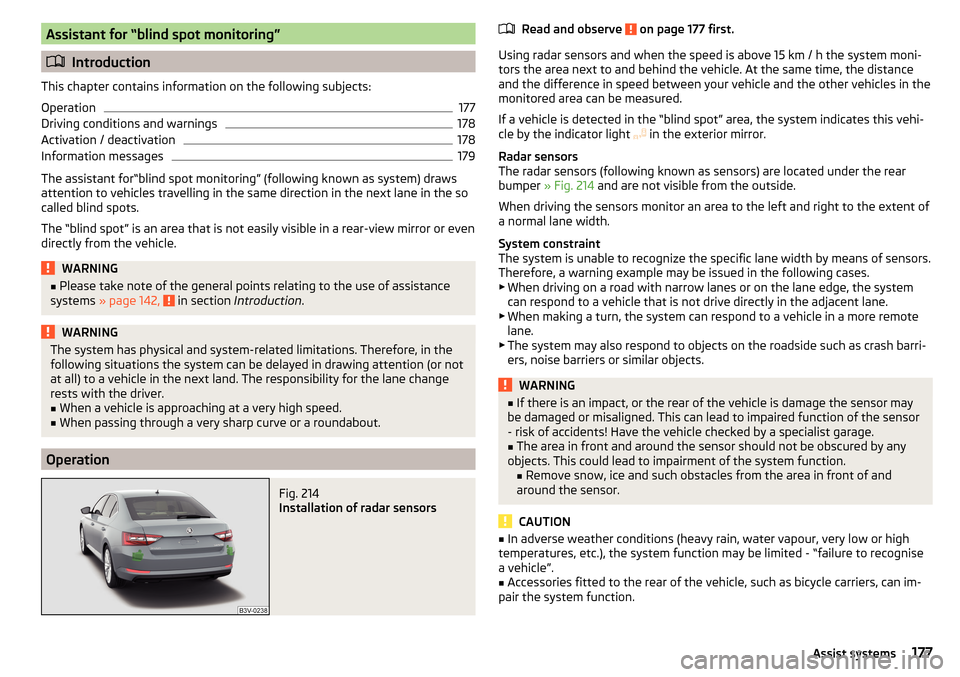
The radar sensors (following known as sensors) are located under the rear
bumper » Fig. 214 and are not visible from the outside.
When driving the sensors monitor an area to the left and right to the extent of
a normal lane width.
System constraint
The system is unable to recognize the specific lane width by means of sensors. Therefore, a warning example may be issued in the following cases.
▶ When driving on a road with narrow lanes or on the lane edge, the system
can respond to a vehicle that is not drive directly in the adjacent lane.
▶ When making a turn, the system can respond to a vehicle in a more remote
lane.
▶ The system may also respond to objects on the roadside such as crash barri-
ers, noise barriers or similar objects.
WARNING■ If there is an impact, or the rear of the vehicle is damage the sensor may
be damaged or misaligned. This can lead to impaired function of the sensor
- risk of accidents! Have the vehicle checked by a specialist garage.■
The area in front and around the sensor should not be obscured by any
objects. This could lead to impairment of the system function. ■ Remove snow, ice and such obstacles from the area in front of and
around the sensor.
CAUTION
■ In adverse weather conditions (heavy rain, water vapour, very low or high
temperatures, etc.), the system function may be limited - “failure to recognise
a vehicle”.■
Accessories fitted to the rear of the vehicle, such as bicycle carriers, can im-
pair the system function.
177Assist systems
Page 183 of 276

FunctionFig. 217
Camera viewing range for traffic
sign recognition
Fig. 218
Instrument cluster display: Display examples
Read and observe
on page 180 first.
Description of indications and displayed traffic signs
Display » Fig. 218Display of detected traffic signs in the menu item Driving data → Road signAdditional display (monochromatic display)Additional display (colour display)
The system can display the following (vertical) traffic signs where identified.
▶ Speed limit.
▶ Overtaking prohibited.
Additional signs, such as 'when wet' or signs which only apply for a limited
time can also be displayed.
The system works on the basis of the data captured by the camera and is only
able to show traffic signs which are in the camera's “viewing range” » Fig. 217.
Data from the camera is supplemented by information from the Infotainment
Navigation. This is the reason why traffic signs with maximum speeds can also
be shown on sections of roads which do not have any traffic signs.
Warning when exceeding the speed limit
The warning when exceeding the permissible speed can be activated and set
in the Infotainment (based on the recognized road sign) » Owner´s Manual In-
fotainment , chapter CAR - vehicle settings .
Mode when towing a trailer
For vehicles with a factory-fitted towing device, it is possible in the Infotain-
ment to enable or disable the relevant traffic signs for trailer operation and the
top speed for the towing a trailer » Owner´s Manual Infotainment , chap-
ter CAR - vehicle settings .
The system may not be available or may only be available to a limited extent
in the following situations.
▶ Poor visibility conditions, e.g. fog, heavy rain, thick snowfall.
▶ The camera is blinded by the sun.
▶ The camera is blinded by the oncoming traffic.
▶ The camera “viewing range” is obstructed by an obstacle.
▶ Travelling at high speed.
▶ The traffic signs are fully or partially obscured (e.g. by trees, snow, dirt or
other vehicles).
▶ The traffic signs are not standard (round with a red border).
▶ The traffic signs are damaged or bent.
▶ The traffic signs are attached to flashing neon signs.
▶ The traffic signs were changed (the navigation data are out of date).
Additional display
Read and observe
on page 180 first.
If the menu item
Road sign
is currently not shown » Fig. 218 on page 181 -
, the
road sign with the speed limit will appear in the upper display area of the in-
strument cluster » Fig. 218 on page 181 -
,
.
If several traffic signs are detected simultaneously, the next traffic sign will al- so in some cases be displayed in the colour display - . All detected traffic
signs can be displayed in the menu item
Road sign
- .
The additional display can be enabled or disabled in the Infotainment » Owner
´s Manual Infotainment , chapter CAR - vehicle settings .
181Assist systems
Page 194 of 276

ŠKODA Service Partners are liable for any defects of ŠKODA Genuine Accesso-
ries for a period of 2 years after installation or delivery in accordance with the
materials defect liability, unless agreed otherwise in the purchase agreement
or any other agreements. You should keep the approved warranty certificate
and the invoices for these accessories for this period of time, so that the com-
mencement of the term can be verified.
ŠKODA Service Partners also stock a range of suitable car care products and all
parts that are subject to natural wear-and-tear, such as tyres, batteries, bulbs
and wiper blades.
Note
The accessories authorized by the company ŠKODA AUTO a.s. will be offered
by the ŠKODA Partners in all countries where the company ŠKODA AUTO a.s.
has a sales and after-sales service network. This will usually be in the form of a
printed catalogue of ŠKODA Genuine Accessories, in the form of separate prin-
ted brochures or in the form of ŠKODA Genuine Accessories on the ŠKODA
Partner websites.
Spoiler
Read and observe
on page 190 first.
If your new vehicle is fitted with a spoiler on the front bumper in combination
with the spoiler on the luggage compartment lid, the following instructions
must be adhered to. ▶ For safety reasons, the vehicle must only be fitted with a spoiler on the front
bumper in combination with the associated spoiler on the luggage compart-
ment lid.
▶ This kind of spoiler cannot be left on the front bumper either on its own, in
combination with another spoiler not on the luggage compartment lid or in
combination with an unsuitable spoiler on the luggage compartment lid.
▶ We recommend that you consult the ŠKODA Service Partner for any repairs
to or replacement, addition or removal of spoilers.
WARNING■ If work on your vehicle's spoilers is not carried out properly, this can lead
to operational faults - risk of accident and serious injuries.■
If a front spoiler, full wheel trim, etc. is mounted retrospectively, it must
be ensured that the air supply to the front wheel brakes is not reduced.
The front brakes may overheat which can have a negative impact on the
functioning of the braking system – risk of accident!
Component protection
Read and observe
on page 190 first.
Some electronic vehicle components (such as the instrument cluster) are fac-
tory-equipped with component protection.
Component protection has been developed as a protection mechanism for the
following situations. ▶ Impairment of factory- or garage-fitted electronic components after installa-
tion in another vehicle (for example, after a theft).
▶ Impairment of electronic components used outside the vehicle.
▶ The possibility of a legitimate installation or change of electronic compo-
nents for repairs at a specialist garage.
The activated component protection can be realized by functional limitations
of the specific electronic component. Seek help from a specialist garage.
Airbags
Read and observe
on page 190 first.
WARNING■Modifications, repairs and technical alterations that have been carried out
unprofessionally can cause damage and operational faults, and can also se-
riously impair the effectiveness of the airbag system – risk of accident and
fatal injury!■
A change to the vehicle's wheel suspension, including the use of non-ap-
proved wheels and tire combinations, can alter the functioning of the air-
bag system - risk of accident and fatal injury!
WARNINGInformation on the use of the airbag system■Never install any airbag parts into the vehicle that have been removed
from old cars or have been recycled.■
Never install damaged airbag parts in the vehicle. The airbags may then
not be deployed properly or even at all in the event of an accident.
192General Maintenance
Page 211 of 276
CAUTION■Under no circumstances must radiator antifreeze or other additives be added
to the windscreen washer fluid.■
If the vehicle is fitted with a headlight cleaning system, only cleaning prod-
ucts which do not attack the polycarbonate coating of the headlights must be
added to the windscreen washer fluid.
■
Do not remove the filter from the windscreen washer fluid reservoir when re-
filling, as this may cause contamination of the liquid transportation system,
leading in turn to a windscreen washer system malfunction.
Engine oil
Introduction
This chapter contains information on the following subjects:
Specification
209
Checking the oil level
210
Replenishing
210
The engine has been factory-filled with a high-grade oil that can be use
throughout the year - except in extreme climate zones.
The engine oils are undergoing continuous further development. Thus the in- formation stated in this Owner's Manual is only correct at the time of publica-
tion.
ŠKODA Service Partners are informed about the latest changes by the manu-
facturer. We therefore recommend that the oil change be completed by a
ŠKODA Service Partner.
The specifications (VW standards) stated in the following can be indicated sep-
arately or together with other specifications on the bottle.
The engine oil should be changed after specified service intervals » page 49.
WARNINGThe engine compartment of your car is a hazardous area. The following
warning instructions must be followed at all times when working in the en-
gine compartment » page 206.
CAUTION
Do not pour any additives into the engine oil – risk of serious damage to the
engine parts.Note■ Before a long drive we recommend that you purchase and carry with you en-
gine oil which complies with the specification for your vehicle.■
We recommend that you use oils from ŠKODA Original Accessories.
■
If oil comes into contact with your skin, the affected area must be washed
thoroughly.
Specification
Read and observe
and on page 209 first.
Vehicles with variable service intervals
Petrol enginesSpecification1.4 l / 92 kW TSI
VW 504 00
1.4 l/110 kW TSI1.8 l/132 kW TSI2.0 l/162, 206 kW TSIDiesel enginesSpecification1.6 ltr. / 88 kW TDI CRVW 507 002.0 l/110, 130, 140 kW TDI CR
Vehicles with fixed service intervals
Petrol enginesSpecification1.4 l / 92 kW TSI
VW 502 00
1.4 l/110 kW TSI1.8 l/132 kW TSI2.0 l/162, 206 kW TSIDiesel enginesSpecification1.6 ltr. / 88 kW TDI CRVW 507 002.0 l/110, 130, 140 kW TDI CR
Engine oil VW 505 01 can optionally be used in diesel engines without a DPF.
209Inspecting and replenishing
Page 214 of 276
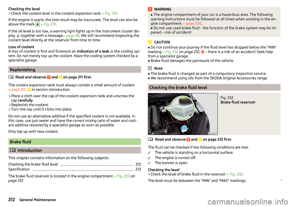
Checking the level›Check the coolant level in the coolant expansion tank » Fig. 231.
If the engine is warm, the test result may be inaccurate. The level can also be
above the mark A
» Fig. 231 .
If the oil level is too low, a warning light lights up in the instrument cluster dis-
play
together with a message » page 38. We still recommend inspecting the
coolant level directly at the reservoir from time to time.
Loss of coolant
A loss of coolant is first and foremost an indication of a leak in the cooling sys-
tem. Do not merely top up the coolant. Have the cooling system checked by a
specialist garage.
Replenishing
Read and observe
and on page 211 first.
The coolant expansion tank must always contain a small amount of coolant» page 211, in section Introduction .
›
Place a cloth over the cap of the coolant expansion tank and unscrew the
cap carefully .
›
Replenish the coolant.
›
Turn the cap until it clicks into place.
Do not use an alternative additive if the specified coolant is not available. In
this case, use just water and have the correct mixing ratio of water and cool-
ant additive restored by a specialist garage as soon as possible.
Only top up with new coolant.
Brake fluid
Introduction
This chapter contains information on the following subjects:
Checking the brake fluid level
212
Specification
213
The brake fluid reservoir is located in the engine compartment » Fig. 232 on
page 212 .
WARNING■
The engine compartment of your car is a hazardous area. The following
warning instructions must be followed at all times when working in the en-
gine compartment » page 206.■
Do not use used brake fluid - the function of the brake system may be im-
paired – risk of accident!
CAUTION
■ Do not continue your journey if the fluid level has dropped below the “MIN”
marking » Fig. 232 on page 212 , - there is a risk of an accident! Seek help
from a specialist garage.■
Brake fluid damages the paintwork of the vehicle.
Note
■ The brake fluid is changed as part of a compulsory inspection service.■We recommend using oils from the ŠKODA Original Accessories range.
Checking the brake fluid level
Fig. 232
Brake fluid reservoir
Read and observe and on page 212 first.
The fluid can be checked if the following conditions are met.
The vehicle is standing on a horizontal surface.
The engine is turned off.
The bonnet is open.
Checking the level
›
Check the level of brake fluid in the reservoir » Fig. 232.
The level must be between the “MIN” and “MAX” markings.
212General Maintenance
Page 216 of 276

WARNING■The use of open flames and light should be avoided.■Smoking and radio triggering activities should be avoided.■
Never use a damaged vehicle battery – risk of explosion!
■
Never charge a frozen or thawed vehicle battery – risk of explosion and
chemical burns!
■
Replace a frozen vehicle battery.
■
Never jump-start vehicle batteries with an electrolyte level that is too low
– risk of explosion and caustic burns.
CAUTION
■ Improper handling of the vehicle battery may cause damage.■Ensure that battery acid does not come into contact with the bodywork – risk
of damage to the paintwork.■
If the vehicle has not been driven for more than 3 to 4 weeks, the battery will
discharge. Prevent the battery from discharging by disconnecting the battery's
negative terminal
or continuously charging the battery with a very low
charging current.
■
Do not place the battery in direct daylight in order to protect the vehicle bat-
tery housing from the effects of ultra-violet light.
■
If the vehicle is frequently used for making short trips, the vehicle battery
will not have time to charge up sufficiently and may discharge.
Note
■ We recommend having all work on the vehicle battery carried out by a spe-
cialist garage.■
You should replace batteries older than 5 years.
Opening the cover
Fig. 233
Polyester cover of vehicle bat-
tery
Read and observe and on page 213 first.
The battery is located in the engine compartment. For some equipment var- iants, it is located underneath a polyester cover » Fig. 233.
›
Fold out the cover on the battery in the direction of the arrow.
The battery cover is installed in reverse order.
Checking the battery electrolyte level
Fig. 234
Vehicle battery: Electrolyte level
indicator
Read and observe and on page 213 first.
On vehicles with a vehicle battery fitted with a colour indicator, the electrolyte
level can be determined by looking at the change in colour of this display.
Air bubbles can influence the colour of the indicator. For this reason carefully
knock on the indicator before carrying out the check.
Check
Black colour - electrolyte level is correct.
Colourless or light yellow colour - electrolyte level too low, the battery must be
replaced.
For technical reasons, on vehicles with the description “AGM”, the electrolyte
level cannot be checked.
Vehicles with the START-STOP system are fitted with a battery control unit for
checking the energy level for the recurring engine starts.
We recommend that you have the acid level checked regularly by a specialist
garage, especially in the following cases. ▶ High external temperatures.
▶ Longer day trips.
▶ After each charge.
214General Maintenance
Page 220 of 276
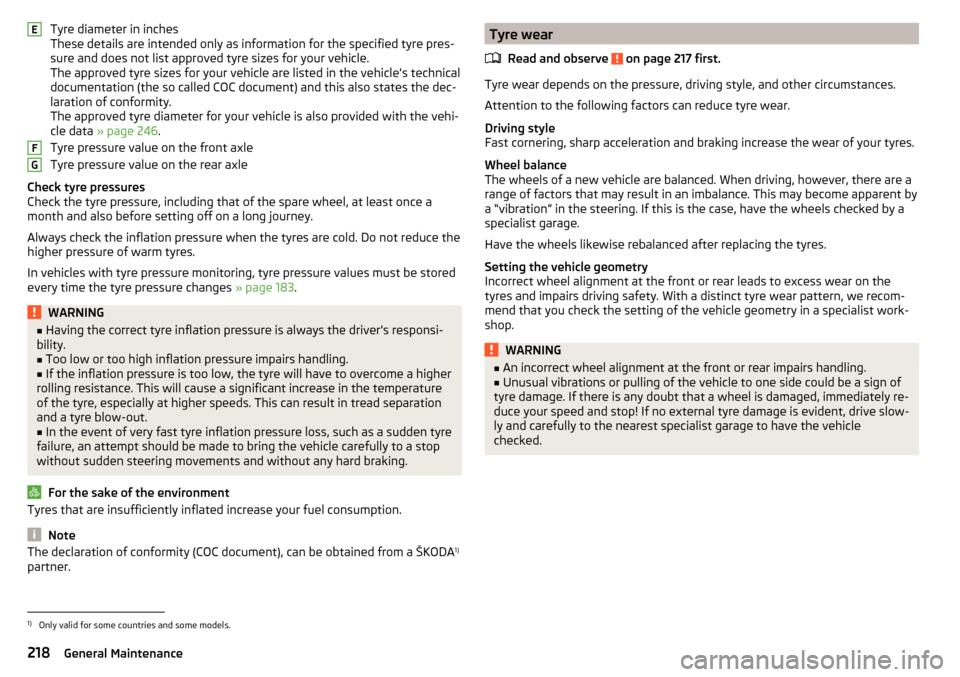
Tyre diameter in inches
These details are intended only as information for the specified tyre pres-
sure and does not list approved tyre sizes for your vehicle.
The approved tyre sizes for your vehicle are listed in the vehicle's technical
documentation (the so called COC document) and this also states the dec-
laration of conformity.
The approved tyre diameter for your vehicle is also provided with the vehi-
cle data » page 246 .
Tyre pressure value on the front axle
Tyre pressure value on the rear axle
Check tyre pressures
Check the tyre pressure, including that of the spare wheel, at least once a
month and also before setting off on a long journey.
Always check the inflation pressure when the tyres are cold. Do not reduce the
higher pressure of warm tyres.
In vehicles with tyre pressure monitoring, tyre pressure values must be stored
every time the tyre pressure changes » page 183.WARNING■
Having the correct tyre inflation pressure is always the driver's responsi-
bility.■
Too low or too high inflation pressure impairs handling.
■
If the inflation pressure is too low, the tyre will have to overcome a higher
rolling resistance. This will cause a significant increase in the temperature
of the tyre, especially at higher speeds. This can result in tread separation
and a tyre blow-out.
■
In the event of very fast tyre inflation pressure loss, such as a sudden tyre
failure, an attempt should be made to bring the vehicle carefully to a stop
without sudden steering movements and without any hard braking.
For the sake of the environment
Tyres that are insufficiently inflated increase your fuel consumption.
Note
The declaration of conformity (COC document), can be obtained from a ŠKODA 1)
partner.EFGTyre wear
Read and observe
on page 217 first.
Tyre wear depends on the pressure, driving style, and other circumstances.
Attention to the following factors can reduce tyre wear.
Driving style
Fast cornering, sharp acceleration and braking increase the wear of your tyres.
Wheel balance
The wheels of a new vehicle are balanced. When driving, however, there are a
range of factors that may result in an imbalance. This may become apparent by
a “vibration” in the steering. If this is the case, have the wheels checked by a
specialist garage.
Have the wheels likewise rebalanced after replacing the tyres.
Setting the vehicle geometry
Incorrect wheel alignment at the front or rear leads to excess wear on the
tyres and impairs driving safety. With a distinct tyre wear pattern, we recom-
mend that you check the setting of the vehicle geometry in a specialist work-
shop.
WARNING■ An incorrect wheel alignment at the front or rear impairs handling.■Unusual vibrations or pulling of the vehicle to one side could be a sign of
tyre damage. If there is any doubt that a wheel is damaged, immediately re-
duce your speed and stop! If no external tyre damage is evident, drive slow-
ly and carefully to the nearest specialist garage to have the vehicle
checked.1)
Only valid for some countries and some models.
218General Maintenance