change time SKODA SUPERB 2015 3.G / (B8/3V) Owner's Manual
[x] Cancel search | Manufacturer: SKODA, Model Year: 2015, Model line: SUPERB, Model: SKODA SUPERB 2015 3.G / (B8/3V)Pages: 276, PDF Size: 42.14 MB
Page 6 of 276
On-board literature
You will always find this Owner's Manual and the Service Plan included in the
on-board literature for your vehicle.
Depending on the equipment, the on-board literature can also include the In-
fotainment Owner´s Manual and in some countries also the brochure On the
road .
Owner's Manual
These Owner´s Manual apply to all body variants of the vehicle and all related
model versions as well as all equipment levels .
This Owner's Manual describes all possible equipment variants without identi-
fying them as special equipment, model variants or market-dependent equip-
ment. Consequently, this vehicle does not contain all of the equipment com-
ponents described in this Owner's Manual.
The level of equipment in your vehicle refers to your purchase contract for the vehicle. For any questions regarding the scope of equipment, please contact a
ŠKODA Partner.
The Pictures in this Owner's Manual are for illustrative purposes only. The il-
lustrations can differ in minor details from your vehicle; they are only intended
to provide general information.
ŠKODA AUTO a.s. pursues a policy of ongoing product and model development
with all vehicles. Changes in terms of supply scope are possible at any time
with regard to design, equipment and technology. The information listed in
this Owner's Manual corresponds to the information available at the time of
going to press.
Therefore legal claims cannot be made based on the technical data, illustra-
tions and information contained in this Owner's Manual.
We recommend that the web pages that are referred to in this Owner's Man-
ual are displayed using the classic view. If the web pages are displayed using
the mobile view, they may not contain all necessary information.
Service schedule
The service schedule includes the documentation of the vehicle handover,
warranty information and service events.
Infotainment Owner´s Manual
The Infotainment Owner's Manual contains a description of the Infotainment
service and possibly also some functions and vehicle systems.On-the-road brochure
The On The Move brochure contains the importer's customer service number
and the service number in the individual countries as well as the emergency
numbers.
Online user manualsFig. 1
This QR code opens a web page with a model overview of the ŠKODA brand.
The page can also be accessed by entering the following address in the web
browser.
http://www.skoda-auto.com/en/mini-apps/owners-manuals/
▶ Select the desired model - a menu with the user manuals is displayed.
▶ Select the construction period as well as the language.
▶ Select the desired manual - it can be displayed either online or in pdf format.
4On-board literature
Page 11 of 276
WARNING■The front seats and all head restraints must be adjusted to match the
body size at all times and the seat belt must always be fastened properly to
provide the most effective levels of protection to the passengers.■
Each occupant must correctly fasten the seat belt belonging to the seat.
Children must be fastened » page 20, Transporting children safely with a
suitable restraint system.
■
By sitting incorrectly, the occupant is risking life-threatening injuries.
■
The seat backrests must not be tilted too far back when driving, as this
will impair the function of the seat belts and of the airbag system – risk of
injury!
Correct seat position of the driver
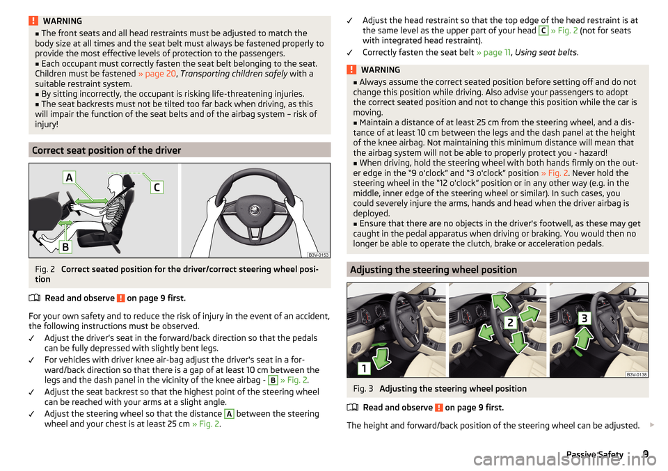
Fig. 2
Correct seated position for the driver/correct steering wheel posi-
tion
Read and observe
on page 9 first.
For your own safety and to reduce the risk of injury in the event of an accident,
the following instructions must be observed.
Adjust the driver’s seat in the forward/back direction so that the pedals
can be fully depressed with slightly bent legs.
For vehicles with driver knee air-bag adjust the driver's seat in a for-
ward/back direction so that there is a gap of at least 10 cm between the
legs and the dash panel in the vicinity of the knee airbag -
B
» Fig. 2 .
Adjust the seat backrest so that the highest point of the steering wheel
can be reached with your arms at a slight angle.
Adjust the steering wheel so that the distance
A
between the steering
wheel and your chest is at least 25 cm » Fig. 2.
Adjust the head restraint so that the top edge of the head restraint is at
the same level as the upper part of your head C » Fig. 2 (not for seats
with integrated head restraint).
Correctly fasten the seat belt » page 11, Using seat belts .WARNING■
Always assume the correct seated position before setting off and do not
change this position while driving. Also advise your passengers to adopt
the correct seated position and not to change this position while the car is
moving.■
Maintain a distance of at least 25 cm from the steering wheel, and a dis-
tance of at least 10 cm between the legs and the dash panel at the height
of the knee airbag. Not maintaining this minimum distance will mean that
the airbag system will not be able to properly protect you - hazard!
■
When driving, hold the steering wheel with both hands firmly on the out-
er edge in the “9 o'clock” and “3 o'clock” position » Fig. 2. Never hold the
steering wheel in the “12 o'clock” position or in any other way (e.g. in the
middle, inner edge of the steering wheel or similar). In such cases, you
could severely injure the arms, hands and head when the driver airbag is
deployed.
■
Ensure that there are no objects in the driver's footwell, as these may get
caught in the pedal apparatus when driving or braking. You would then no
longer be able to operate the clutch, brake or acceleration pedals.
Adjusting the steering wheel position
Fig. 3
Adjusting the steering wheel position
Read and observe
on page 9 first.
The height and forward/back position of the steering wheel can be adjusted.
9Passive Safety
Page 51 of 276
Eco-tipsRead and observe
on page 45 first.
To minimise fuel consumption, fuel economy tips can appear in the display.
Eco tips are indicated next to the letters ECO-TIP.
For instance, if the air-conditioning is on and a window is open, the following
message appears
ECO TIP Air conditioning switched on: Close windows.
Enable/disable » Owner´s Manual Infotainment , chapter CAR - vehicle set-
tings .
Service interval display
Introduction
This chapter contains information on the following subjects:
Displaying the distance and days until the next service interval
49
Service messages
49
Resetting the service interval display
49
The service interval display shows the time and mileage to the next service
event.
The information regarding the service intervals can be found in the service
schedule.
Displaying the distance and days until the next service interval
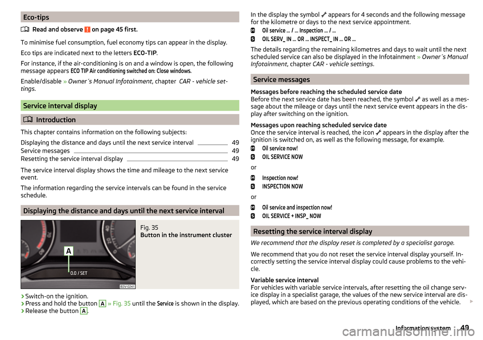
Fig. 35
Button in the instrument cluster
›
Switch-on the ignition.
›
Press and hold the button
A
» Fig. 35 until the
Service
is shown in the display.
›
Release the button
A
.
In the display the symbol appears for 4 seconds and the following message
for the kilometre or days to the next service appointment.Oil service … / … Inspection … / …OIL SERV_ IN … OR … INSPECT_ IN … OR …
The details regarding the remaining kilometres and days to wait until the next
scheduled service can also be displayed in the Infotainment » Owner´s Manual
Infotainment , chapter CAR - vehicle settings .
Service messages
Messages before reaching the scheduled service date
Before the next service date has been reached, the symbol as well as a mes-
sage about the mileage or days until the next service event appears in the dis-
play after switching on the ignition.
Messages upon reaching scheduled service date
Once the service interval is reached, the icon appears in the display after the
ignition is switched on, as well as the following message, for example.
Oil service now!OIL SERVICE NOW
or
Inspection now!INSPECTION NOW
or
Oil service and inspection now!OIL SERVICE + INSP_ NOW
Resetting the service interval display
We recommend that the display reset is completed by a specialist garage.
We recommend that you do not reset the service interval display yourself. In-
correctly setting the service interval display could cause problems to the vehi-
cle.
Variable service interval
For vehicles with variable service intervals, after resetting the oil change serv-
ice display in a specialist garage, the values of the new service interval are dis-
played, which are based on the previous operating conditions of the vehicle.
49Information system
Page 54 of 276

After changing the password/PIN, the connection to SmartGate must be re-es-
tablished on the communication device to be connected using the new pass-
word or new PIN code.
If the password/PIN code is still set to the preset factory password/PIN code,
you are requested to change the password/PIN code after starting the ŠKODA
application. Without changing the password/PIN code, you are unable to use
the application.
Changing the password for the Wi-Fi connection›
Open the SmartGate web interface.
›
In the menu item “WPA / WPA2 key:” enter the new password (8 to 63 alpha-
numeric, special, lower and upper case characters).
›
Confirm the password change by tapping on the “Save” button.
›
Restart SmartGate by tapping on the “Reboot” 1)
button.
Changing the PIN code for the Wi-Fi Direct connection
›
Open the SmartGate web interface.
›
In the menu item “WiFi Direct PIN:” Enter the new PIN code (6 digits).
›
Confirm the PIN code change by tapping on the “Save” button.
›
Restart SmartGate by tapping on the “Reboot” 1)
button.
Note
If you have forgotten your password/PIN code for connecting to SmartGate,
SmartGate must be reset to the factory settings in a specialist workshop.Unlocking and opening
Unlocking and locking
Introduction
This chapter contains information on the following subjects:
Unlocking / locking with the remote control key
53
KESSY override key removal
54
Unlocking / locking - KESSY
54
Locking / unlocking the vehicle with the central locking button
55
Safe securing system
55
Individual settings
56
Opening/closing a door
56
Child safety lock
57
Malfunctions
57
Your car is equipped with a central locking system.
The central locking system allows you to lock and unlock all doors, the fuel fill-
er flap and boot lid at the same time. The functions of the central locking sys-
tem can be individually adjusted » page 56.
After unlocking, depending on vehicle equipment and setting the following is
valid for the central locking. ▶ The turn signal lights flash twice as confirmation that the vehicle has been
unlocked.
▶ An double audible signal sounds additionally on vehicles which are fitted
with the anti-theft alarm system.
▶ The doors, the boot lid and the fuel filler flap are unlocked.
▶ The interior lamp illuminates.
▶ The SafeLock system is switched off.
▶ The indicator light in the driver door stops flashing.
▶ The exterior mirrors are set into the driving position.
▶ The anti-theft alarm system is deactivated.
1)
If the “Reboot” button is not displayed, you must manually restore the web browser display.
52Using the system
Page 71 of 276

If during the “comfort flashing” the operating lever in the opposite side is
pressed, then the blinking stops.
The “Lane change flash” can be activated/deactivated in the Infotainment
» Owner´s Manual Infotainment , chapter CAR - vehicle settings .WARNINGOnly turn on the main beam or the headlight flasher if other road users will
not be dazzled.
Automatic driving lamp control
Fig. 56
Light switch: AUTO position
Read and observe on page 67 first.
The light switch is in position
» Fig. 56 then depending on the equipment
the automatic switch on / off the lights corresponding to the light or weather
conditions (rain) takes place.
The sensitivity of the sensor for the determination of the ambient light can be
adjusted in the infotainment » Owner´s Manual Infotainment , chapter CAR -
vehicle settings .
If the light switch is in position
, the lettering
illuminates next to the
light switch. If the light is switched on automatically, the symbol
next to the
light switch also lights up.
Automatic driving light control during rain
The dipped beam is switched on automatically if the following conditions are
met.
The function is activated.
The light switch is in the position
.
The windscreen wipers are on for more than 30 s.
The light turns off about 4 minutes after turning off the wipers.
Automatic headlight control in rain can be activated or deactivated in the Info-
tainment » Owner´s Manual Infotainment , chapter CAR - Vehicle settings .
CAUTION
Poorer visibility is evaluated by a motor mounted below the windscreen in the
holder of the interior mirror sensor. Do not attach any stickers or similar ob-
jects in front of the light sensor on the windscreen in order to avoid impairing
the function or its reliability.
Xenon headlight
Read and observe
on page 67 first.
The xenon headlight (hereinafter referred as system) ensures that the roads
are illuminated independent of the traffic and weather conditions.
The system automatically adjusts the cone of light in front of the vehicle based
on the driving information (such as vehicle speed and loading situation, use of
the windscreen wipers, selected driving profile, vehicle position according to
the data from Infotainment navigation).
The system works as long as the light switch is in position .
The system operates automatically in the following modes.
Out of town mode
The cone of light in front of the vehicle is similar to the low beam.
City mode
The cone of light in front of the vehicle is adjusted so that it also illuminates
the adjacent pavements, crossings, pedestrian crossings etc. The mode is ac-
tive at a speed of 15-50 km / h.
Motorway mode
The cone of light in front of the vehicle is adjusted so that the driver can re-
spond in time to an obstruction or other hazard in time. The mode is active at
speeds above 110 km/h.
Rain mode
The cone of light in front of the vehicle is adjusted so that the driver can re-
duce the glare from oncoming vehicles in rain.
The mode is active at speeds of 50 – 90 km/h and if the windscreen wipers
continuously operate for a period of time longer than about 2 minutes. The de-
activation of the mode is carried out a few minutes after switching off the wip-
er.
69Lights and visibility
Page 79 of 276

Sun screen in the rear doorsFig. 68
Sun blind on the rear door
Read and observe
on page 75 first.
Extending
›
Pull out the sun blind with the handle
A
in the direction of arrow » Fig. 68
and hang it in the bracket
B
on the top edge of the door.
Retracting
›
Remove the sun blind from the handle
A
» Fig. 68 out of the bracket and
hold it in such a way that it can roll up slowly without being damaged.
Windscreen wipers and washers
Introduction
This chapter contains information on the following subjects:
Windscreen wipers and washers
78
Headlight cleaning system
78
The windscreen wipers and the wash system only operate if the ignition is
switched on and the bonnet and boot are closed.
Winter setting of the windscreen wiper
If the windscreen wipers are in rest position, they cannot be folded out from
the windscreen. For this reason we recommend adjusting the windscreen wip-
ers in winter so that they can be folded out from the windscreen easily.
▶ Switch on the windscreen wipers.
▶ Switch off the ignition.
The windscreen wipers remain in the position in which they were when
switching off the ignition.
The service position can also be used as a winter position » page 237.WARNING■
Properly maintained windscreen wiper blades are essential for clear visi-
bility and safe driving » page 198, Wiper blades .■
Do not use the windscreen washer system at low temperatures, without
heating the windscreen beforehand. The window washer fluid could other-
wise freeze on the windscreen and restrict the view to the front.
CAUTION
■ In cold temperatures and during the winter, check before switching on the
ignition that the wiper blades are not frozen to the windscreen. If the wind-
screen wipers are switched on when the blades are frozen to the windscreen,
this may damage both the blades and windscreen wiper motor!■
Carefully peel frozen wiper blades off the pane.
■
Remove snow and ice from the windscreen wipers before driving.
■
If the windscreen wipers are handled carelessly, there is a risk of damage to
the windscreen.
■
Do not switch on the ignition if the front wiper arms are retracted. The wiper
arms could damage the paint of the bonnet.
■
If there is an obstacle on the windscreen, the wiper will try to push away the
obstacle. The wiper stops automatically after 5 attempts to eliminate the ob-
stacle, in order to avoid a damage to the wiper. Remove the obstacle and
switch the wiper on again.
Note
■ Each time the ignition switches off for the third time, the position of the
windscreen wipers changes. This counteracts an early fatigue of the wiper rub-
bers.■
The windscreen washer nozzles for the windscreen are heated when the en-
gine is running and the outside temperature is less than approx. +10 °C.
77Lights and visibility
Page 86 of 276

When the vehicle is next unlocked using the same key, the driver's seat and
the external mirrors assume the positions stored in the memory of this key.
Saving front passenger mirror settings when reversing
The function of lowering the passenger mirror surface when reversing must be
enabled in Infotainment » Owner´s Manual Infotainment , chapter CAR - Vehi-
cle Settings .›
Unlock the vehicle with the relevant remote control key.
›
Switch-on the ignition.
›
Turn the knob for the external mirror control to the position for the passen-
ger side mirror adjustment » page 80.
›
Engage reverse gear.
›
Adjust the front passenger's mirror to the desired position.
›
Disengage reverse gear.
The adjusted position of the exterior mirror is stored in the remote control key
memory.
Disable function of automatic storage
›
Unlock the vehicle with the remote control key.
›
Press the button (Position
A
» Fig. 75 on page 83 ) and hold.
›
At the same time, press the button on the remote control key within
10 seconds.
The successful deactivation of the automatic storage function for each key is
confirmed by an acoustic signal.
Stopping the current adjustment
›
Press any button on the driver's seat or the button on the remote control
key.
Folding front passenger seat
Fig. 76
Folding the front passenger seat
forward
Read and observe on page 81 first.
The front passenger seat can be folded forward into a horizontal position.
Folding forward
›
Place the lever in position
1
» Fig. 76 .
›
Remove the cover in the direction of the arrow
2
.
The locking mechanism must audibly snap into place.
Folding backwards
›
Place the lever in position
1
» Fig. 76 .
›
Fold the seat backrest in the opposite direction of the arrow
2
.
The locking mechanism must audibly snap into place.
WARNING■ The front passenger airbag should be switched off when transporting ob-
jects on the seat which was folded forwards » page 19.■
Adjust the seat backrest only when the vehicle is stationary.
■
When moving the seat backrest, make sure the seat backrest has been
properly secured – check by pulling on the seat backrest.
■
If the seat backrest is folded, passengers may only be transported on the
outer seat behind the driver.
■
When moving the seat backrest, keep limbs out of the area between the
seat and seat backrest – risk of injury!
■
Never transport the following items on the seat backrest when folded
forwards. ■ Objects that could restrict the driver's view.
■ Objects which make it impossible for the driver to control the vehicle,
e.g. if they roll under the pedals, or could protrude into the driver's zone. ■ Objects which could lead to injury to passengers due to a change of di-
rection or braking manoeuvre when accelerating sharply.
84Using the system
Page 108 of 276

When transporting cargo the following the instructions must be adhered to
▶ When transporting heavy objects, the driving characteristics change due to
the shift in centre-of-gravity. The speed and style of driving must be adjus-
ted accordingly.
▶ The cargo is stowed in the luggage compartment. To prevent this from mov-
ing it should be secured with suitable lashing straps to the lashing eyes or
secured with fixing nets.
▶ Distribute loads as evenly as possible.
▶ Place heavy objects as far forward as possible.
▶ The transported items must be stowed in such a way that no objects are able
to slip forward on sudden driving or braking manoeuvres – risk of injury!
▶ Tyre pressure is to match the load.
▶ When transporting loads in the luggage compartment that has been en-
larged by folding the rear seats forward, ensure the safety of the passengers
transported on the other rear seats .
In the event of an accident, even small and light objects gain so much kinetic energy that they can cause severe injuries.
The magnitude of the kinetic energy is dependent on the speed at which the
vehicle is travelling and the weight of the object.
Example: In the event of a frontal collision at a speed of 50 km/h, an object
with a weight of 4.5 kg produces an energy, which corresponds to 20 times its
own weight. This means that it results in a weight of approx. 90 kg “ ”.
Luggage compartment light
The warning light turns on when tailgate is opened.
The warning light turns off when the tailgate is closed.
If the boot lid is open and the ignition switched off, the light will extinguish
automatically after around 10 minutes.
The luggage compartment illumination using the removable lamp » page 114.WARNING■
Never exceed the maximum permissible load of the respective fasteners,
nets, hooks etc. Heavy objects were not secured sufficiently – risk of injury!■
If the cargo is tied down with unsuitable or damaged lashing straps, inju-
ries can occur in the event of braking manoeuvres or accidents.
■
Loose cargo can be thrown forward during a sudden manoeuvre or in case
of an accident and can injure the occupants or other road users.
■
Loose cargo could hit a deployed airbag and injure occupants – danger of
death!
CAUTION■ Never exceed the maximum permissible load of the respective fasteners,
nets, hooks etc. - these could be damaged.■
Make sure that transported objects with sharp edges do not damage the
threads of the following devices. ■Rear window heater.
■ Rear window with an integrated antenna.
■ Integrated antenna in the rear side windows.
Fastening elements
Fig. 127
Fastening elements: Variant 1/ Variant 2
Read and observe
and on page 106 first.
The fasteners are located on both sides of the luggage compartment.
Overview of the fastening elements » Fig. 127
Fastening elements for fastening fixing nets
Lashing eyes for fastening items of luggage and fixing nets
The maximum permissible load for the individual lashing eyes
B
is 350 kg.
For vehicles with the variable loading floor, the luggage can only be secured
using the eyelets
B
when the variable loading floor is in the lower position
» page 115 .
AB106Using the system
Page 139 of 276
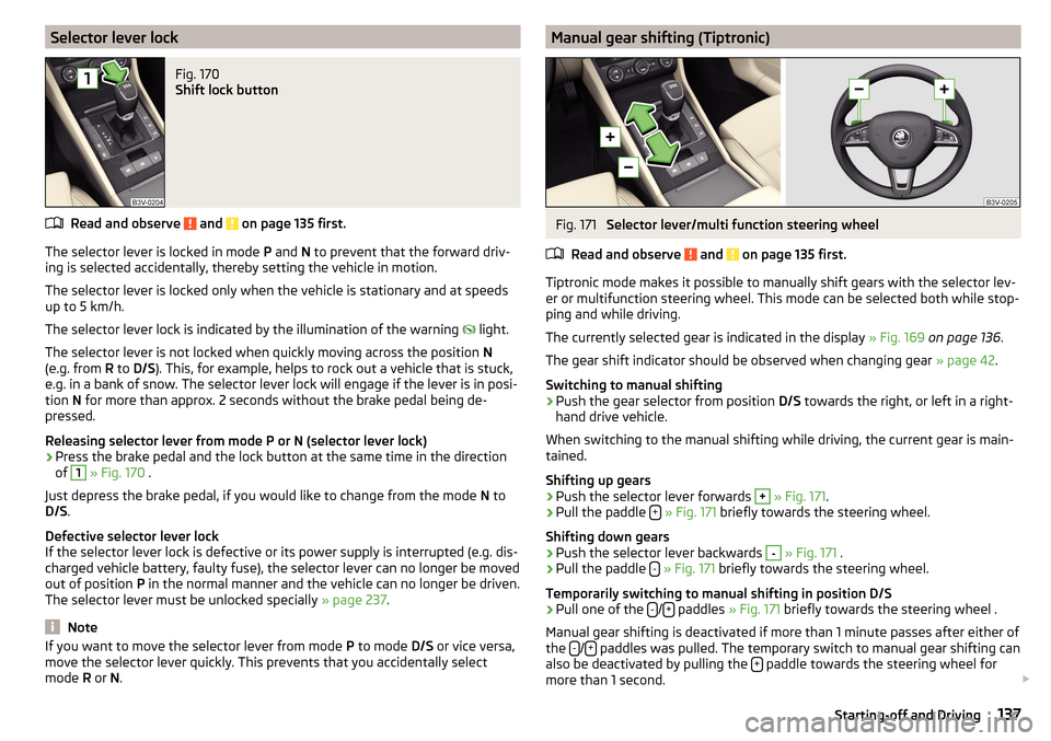
Selector lever lockFig. 170
Shift lock button
Read and observe and on page 135 first.
The selector lever is locked in mode P and N to prevent that the forward driv-
ing is selected accidentally, thereby setting the vehicle in motion.
The selector lever is locked only when the vehicle is stationary and at speeds
up to 5 km/h.
The selector lever lock is indicated by the illumination of the warning light.
The selector lever is not locked when quickly moving across the position N
(e.g. from R to D/S ). This, for example, helps to rock out a vehicle that is stuck,
e.g. in a bank of snow. The selector lever lock will engage if the lever is in posi-
tion N for more than approx. 2 seconds without the brake pedal being de-
pressed.
Releasing selector lever from mode P or N (selector lever lock)
›
Press the brake pedal and the lock button at the same time in the direction
of
1
» Fig. 170 .
Just depress the brake pedal, if you would like to change from the mode N to
D/S .
Defective selector lever lock
If the selector lever lock is defective or its power supply is interrupted (e.g. dis-
charged vehicle battery, faulty fuse), the selector lever can no longer be moved
out of position P in the normal manner and the vehicle can no longer be driven.
The selector lever must be unlocked specially » page 237.
Note
If you want to move the selector lever from mode P to mode D/S or vice versa,
move the selector lever quickly. This prevents that you accidentally select
mode R or N.Manual gear shifting (Tiptronic)Fig. 171
Selector lever/multi function steering wheel
Read and observe
and on page 135 first.
Tiptronic mode makes it possible to manually shift gears with the selector lev-
er or multifunction steering wheel. This mode can be selected both while stop-
ping and while driving.
The currently selected gear is indicated in the display » Fig. 169 on page 136 .
The gear shift indicator should be observed when changing gear » page 42.
Switching to manual shifting
›
Push the gear selector from position D/S towards the right, or left in a right-
hand drive vehicle.
When switching to the manual shifting while driving, the current gear is main-
tained.
Shifting up gears
›
Push the selector lever forwards
+
» Fig. 171 .
›
Pull the paddle +
» Fig. 171 briefly towards the steering wheel.
Shifting down gears
›
Push the selector lever backwards
-
» Fig. 171 .
›
Pull the paddle -
» Fig. 171 briefly towards the steering wheel.
Temporarily switching to manual shifting in position D/S
›
Pull one of the -/+ paddles
» Fig. 171 briefly towards the steering wheel .
Manual gear shifting is deactivated if more than 1 minute passes after either of
the -
/+ paddles was pulled. The temporary switch to manual gear shifting can
also be deactivated by pulling the + paddle towards the steering wheel for
more than 1 second.
137Starting-off and Driving
Page 167 of 276
Set distance to the vehicle ahead.
Vehicle detected (control deactivated).
ACC status indications » Fig. 203
Regulation is inactive (in the colour display the digits of speed limits is
shown in grey).
Regulation active - no vehicle detected (in the colour display the digits of
the speed limits are highlighted).
Regulation deactivated - no speed stored.
Regulation active - vehicle detected (in the colour display the digits of the
speed limits are highlighted).
Note to reduce speed
If the delay of the ACC is insufficient in relation to the vehicle in front, in the instrument cluster, the warning light lights up and the display shows the
following message.Apply the brake!
Regulation according to the vehicle in the adjacent lane
During regulation your vehicle may be regulated according to the vehicle in the adjacent lane.
This could occur at speeds above about 80 km / h when your vehicle is moving
faster than the vehicle in the adjacent lane on the driver's side. The display
shows the detected vehicle is in the adjacent lane.
Note
Some ACC notifications in the display of the instrument cluster may be hidden
by notifications for other functions. An ACC notification automatically appears
for a brief moment when there is a change in status of the ACC.
Automatic stop-start
Read and observe
on page 163 first.
Vehicles with an automatic transmission can decelerate to a standstill and
start moving again using the ACC.
Decelerate to a standstill
If a vehicle ahead decelerates to a standstill, the ACC will also decelerate your
vehicle to a standstill.
34Starting to drive again after a holding period
As soon as the vehicle ahead starts moving again after a holding period, your
vehicle will also move and the speed will continue to be regulated.
If the preceding vehicle starts moving again after a long break, then to contin-
ue the regulation press the accelerator pedal or lever to position
ad-
just » page 165 , Operation Overview .
Operation Overview
Fig. 204
Operating lever
Read and observe
on page 163 first.
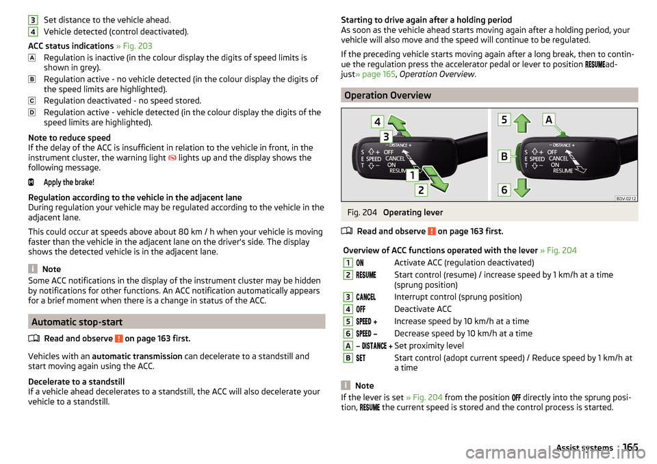
Overview of ACC functions operated with the lever » Fig. 2041Activate ACC (regulation deactivated)2Start control (resume) / increase speed by 1 km/h at a time
(sprung position)3Interrupt control (sprung position)4Deactivate ACC5 Increase speed by 10 km/h at a time6 Decrease speed by 10 km/h at a timeA Set proximity levelBStart control (adopt current speed) / Reduce speed by 1 km/h at
a time
Note
If the lever is set » Fig. 204 from the position directly into the sprung posi-
tion, the current speed is stored and the control process is started.165Assist systems