towing SKODA SUPERB 2016 3.G / (B8/3V) Owner's Manual
[x] Cancel search | Manufacturer: SKODA, Model Year: 2016, Model line: SUPERB, Model: SKODA SUPERB 2016 3.G / (B8/3V)Pages: 336, PDF Size: 53.89 MB
Page 5 of 336
Radio142Operation142
Media
146
Operation
146
Audio sources
149
Images
153
Image viewer
153
Video DVD
155
Video player
155
TV tuner
156
TV function
156
Media Command
158
Operation
158
Telephone
160
Introductory information
160
Pair and connect
163
Use the SIM card in the external module
166
rSAP
167
Telephone functions
168
Text messages (SMS)
172
Hotspot (WLAN) and data connection
174
Hotspot (WLAN)
174
Data connection
175
SmartLink
176
Introductory information
176
Android Auto
177
Apple CarPlay
178
MirrorLink®
178
Navigation
180
Introductory information
180
Search for destination and enter
182
Import my destinations
186
Map
187
Route guidance
190Route192Waypoint mode194
Traffic reports
196
vehicle systems
198
CAR - Vehicle settings
198
Driving
Starting-off and Driving
199
Starting and stopping the engine
199
START-STOPsystem
201
Brakes and Parking
203
Manual gear changing and pedals
205
Automatic transmission
206
Running in the engine and economical
driving
209
Avoiding damage to your vehicle
211
Assist systems
212
General information
212
Braking and stabilisation systems
212
Parking aid (ParkPilot)
215
Rear traffic alert and wizard for “Blind
spot”Monitoring
218
Reversing camera
221
Park Assist
225
Cruise Control System
229
Speed limiter
231
Adaptive Cruise Control (ACC)
233
Front Assist
237
Select the driving mode (Driving Mode
Selection)
240
Proactive occupant protection (Crew Protect
Assist)
242
Lane Departure Warning (Lane Assist)
243
Traffic jam assistant
245
Assistant for emergencies
246
Traffic sign recognition
246Fatigue detection248Tyre pressure monitoring249
Towing device and trailer
250
Hitch
250
Using hitch
252
General Maintenance
Care and maintenance
256
Service work, adjustments and technical
alterations
256
Service intervals
258
Cleaning and care
260
Inspecting and replenishing
264
Fuel
264
AdBlue ®
and its refilling
267
Engine compartment
268
Engine oil
270
Coolant
271
Brake fluid
273
Vehicle battery
273
Wheels
276
Wheels and tyres
276
Operating in winter conditions
278
Do-it-yourself
Emergency equipment and self-help
280
Emergency equipment
280
Changing a wheel
282
Puncture repair kit
285
Jump-starting
287
Towing the vehicle
288
Remote control and removable light -
replacing the battery/batteries
2903Table of Contents
Page 8 of 336
It is the customer's responsibility to prove that it was not the cause.
This ŠKODA warranty does not affect the purchaser's statutory rights from ma-
terials defect liability from the vehicle vendor and other potential claims from
product liability laws.
Mobility warranty
The mobility warranty provides a sense of security when travelling in your ve-
hicle.
If your vehicle stops working on the road due to an unexpected failure, serv-
ices for keeping you moving are provided under the mobility guarantee, which
include the following services for you: Breakdown assistance at the roadside
and towing to a ŠKODA Service partner, technical assistance on the telephone
or on-site commissioning.
If your vehicle is not repaired on the same day, the ŠKODA Service Partner may
provide further services as required, such as replacement transportation (bus,
train etc.) or a courtesy vehicle etc.
More information regarding terms and conditions for the provision of a mobility
warranty for your vehicle can be obtained from your ŠKODA Partner. They will
also provide you with detailed terms and conditions for the mobility warranty
with respect to your vehicle. In the event that there is no mobility warranty
coverage available for your vehicle, you should check with any ŠKODA Service
Partner about the possibility of a subsequent agreement.
Optional ŠKODA extended warranty
If you opted for a ŠKODA extended warranty when purchasing your new car,
the two-year ŠKODA warranty with regards to all free warranty repairs is ex-
tended by the period you chose or until the chosen mileage limit has been
reached, whichever occurs first.
The previously mentioned paint warranty and the warranty against rust perfo-
ration are unaffected by the ŠKODA extended warranty.
The ŠKODA extended warranty does not apply to external and internal foils.
The information on the detailed conditions of the ŠKODA extended warranty is
provided by your ŠKODA partner.
Note
The ŠKODA extended warranty is only available in some countries.6Liability for defects and ŠKODA Warranty for new cars
Page 40 of 336
Other incidents
The illumination of the warning light can have the following reasons.
▶ The vehicle is loaded on one side. Distribute the load evenly.
▶ The wheels of one axle are loaded more heavily (e.g. when towing a trailer or
when driving uphill or downhill).
▶ Snow chains are mounted.
▶ A wheel has been changed.
CAUTION
Under certain circumstances (e.g. sporty style of driving, wintry or unpaved
roads) the warning light can be delayed or does not light up at all.
Brake linings
Read and observe
on page 34 first.
illuminates - the brake pads are worn.
▶ You can drive on, exercising appropriate caution. Seek assistance from a spe-
cialist garage immediately.
Fuel reserve
Read and observe
on page 34 first.
illuminates – the fuel level in the fuel tank is at the reserve level (approxi-
mately 6 litres).
An audible signal sounds as a warning. ▶ Please refuel » page 265.
Note
The text in the display goes out after refuelling and driving a short distance.
Lane Departure Warning (Lane Assist)
Read and observe
on page 34 first.
The warning lights
indicates the state of the Lane Assist system.
More information about the Lane Assist System » page 243.
Turn signal system
Read and observe
on page 34 first.
flashes – the left turn signal is turned on.
flashes – the right turn signal is turned on.
If there is a fault in the turn signal system, the warning light flashes at twice
its normal rate (does not apply when towing).
When the hazard warning light system is switched on, this will cause all of the turn signal lights as well as both warning lights to flash.
Trailer turn signal lights
Read and observe
on page 34 first.
flashes – the trailer turn signal lights are switched on.
If a trailer is hitched and the warning light is not flashing, one of the trailer
turn signal lights has failed.
▶ Check the trailer bulbs.
Fog lights
Read and observe
on page 34 first.
illuminates – the fog lights are switched on.
Speed regulating system / speed limiter
Read and observe
on page 34 first.
illuminates - the vehicle speed is limited by the speed regulating system
and/or the adaptive cruise control or by the speed limiter.
flashes – the speed set with the speed limiter has been exceeded.
Brake pedal (automatic gearbox)
Read and observe
on page 34 first.
lights up – apply the brake.
38Using the system
Page 58 of 336
SafeLockRead and observe
and on page 54 first.
SafeLock prevents the doors from behind opened from inside as well as win-
dow operation. This makes it more difficult for anyone to break into the vehi-
cle.
Switching on
SafeLock switches on when the vehicle is locked.
This function is pointed out by the following message on the display of the in-
strument cluster after the ignition is switched off.
Observe SAFE interlock! Log book!CHECK SAFELOCK
Switch-on display
With the activated SafeLock, the warning light in the driver´s door flashes for 2
seconds in rapid succession, this then starts to flash at longer intervals.
Switching off ▶ By locking twice within 2 seconds.
▶ or: by deactivating the interior monitor and the towing protection
» page 58 .
The warning light in the driver´s door flashes fast for about 2 seconds, goes
out and starts to flash at longer intervals after about 30 seconds.
If the vehicle is locked and the safe securing system is switched off, the door
can be opened separately from the inside by a single pull on opening lever.
The safelock switches on the next time the vehicle is locked.
WARNINGIf the car is locked and the safe securing system activated, no people must
remain in the car as it will then not be possible to either unlock a door or
open a window from the inside. The locked doors make it more difficult for
rescuers to get into the vehicle in an emergency – risk to life!
Individual settings
Read and observe
and on page 54 first.
The following functions of the central locking can be individually adjusted in
infotainment in the
→
→
Opening and closing
menu.
All doors
The function allows you to unlock all doors, the boot lid and the fuel filler flap.
Single door
The function allows you to unlock only the driver's door and the fuel filler flap
with the radio remote control. KESSY allows the unlocking of a single door
which is in the vicinity of the key, as well as the fuel filler flap. The other doors
and the boot lid are only unlocked once the door handle is unlocked or
touched.
Doors on a vehicle side
This function enables you to unlock both doors on the driver's side and the
fuel filler flap with the radio remote control unit. KESSY allows the unlocking of
both doors which are in the vicinity of the key, as well as the fuel filler flap. The
other doors and the boot lid are only unlocked once the door handle is un-
locked or touched.
Automatic locking/unlocking
This function enables the locking of all doors and the boot lid from a speed of
15 km/h. Opening the doors and the boot lid from the outside is not possible.
The renewed unlocking of the doors and the boot lid is carried out when the
ignition key is removed or when the door is opened from inside (depending on
the individual setting for the central locking system).
Note
The individual adjustment of the central locking system is stored (depending
on the Infotainment type) in the active user account personalisation
» page 49 .56Using the system
Page 60 of 336
Failure of the system KESSY
If there is a fault in the KESSY system, the appropriate error message is dis-
played in the instrument cluster.
Low voltage of the key battery
If the voltage of the key battery is too low, a message appears in the display of
the instrument cluster referring to the need to replace the battery. Replace
the battery » page 290.
Anti-theft alarm system
Introduction
This chapter contains information on the following subjects:
Alarm trigger
58
Interior monitor and towing protection
58
The alarm system triggers audible and visual signals if an attempt is made to
break into the vehicle (hereafter referred to as alarm).
The alarm system is activated automatically approximately 30 seconds after the vehicle is locked. This is automatically disabled after release.
CAUTION
Before leaving the vehicle, it must be checked that all of the windows, doors
and the sliding/tilting roof are locked in order to ensure the full functionality of
the anti-theft alarm system.
Note
The alarm system has its own power source, service life of which is 5 years. In
order to ensure functionality of the alarm system, we recommend that you get
the alarm checked after this time by a specialist garage.
Alarm trigger
Read and observe
on page 58 first.
The alarm is triggered when one of the following unauthorised actions is acti-
vated on the vehicle with an activated warning system. ▶ Opening the bonnet.
▶ Opening the boot lid.
▶ Opening the doors.
▶ Manipulation of the ignition lock.
▶
Towing the vehicle.
▶ Movement in the vehicle.
▶ Sudden and significant voltage drop of the electrical system.
▶ Uncoupling the trailer.
An alarm is triggered also when the driver's door is unlocked and opened by
the lock cylinder.
The alarm is switched off by pressing the
button on the key or switching on
the ignition.
Interior monitor and towing protection
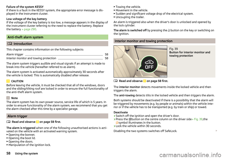
Fig. 39
Button for interior monitor and
towing protection
Read and observe on page 58 first.
The interior monitor detects movements inside the locked vehicle and then
triggers the alarm.
The anti-towing detects tilts in the locked vehicle and then triggers the alarm.
Both systems should be deactivated if there is a possibility that the alarm will
be triggered by movements (e.g. by people or animals) within the vehicle inte-
rior or if the vehicle has to be transported (e.g. by train or ship) or towed.
Deactivate
›
Switch off the ignition and open the driver's door.
›
Press the button on the centre column on the driver side
» Fig. 39,the
symbol illuminates in the button.
›
Lock the vehicle within 30 seconds.
Disabling the two systems switches off SafeLock.
58Using the system
Page 71 of 336
CAUTIONPoorer visibility is evaluated by a sensor mounted below the windscreen in the
holder of the rear-view mirror. Do not cover the sensor - the system can be af-
fected.
Note
The setting (activate/deactivate) of the automatic driving light control during
rain is stored (depending on the Infotainment type) in the active user account
personalisation » page 49.
Xenon headlight
Read and observe
on page 66 first.
The Xenon headlights (hereinafter referred to as just system) use the drivingdata to automatically ensure the for the best possible light cone in front of the
vehicle.
The system will automatically operate in the following modes: urban, extra-ur-
ban, motorway, rain, fog, adjusting the lighting direction of the headlights for
road illumination on bends.
The system works as long as the light switch is in position
.
WARNINGIf there is a system malfunction the headlights are automatically lowered
to the emergency position, which prevents a possible dazzling of oncoming
traffic. This reduces the cone of light in front of the vehicle. Seek help from
a specialist garage.Fog lights/rear fog lightFig. 51
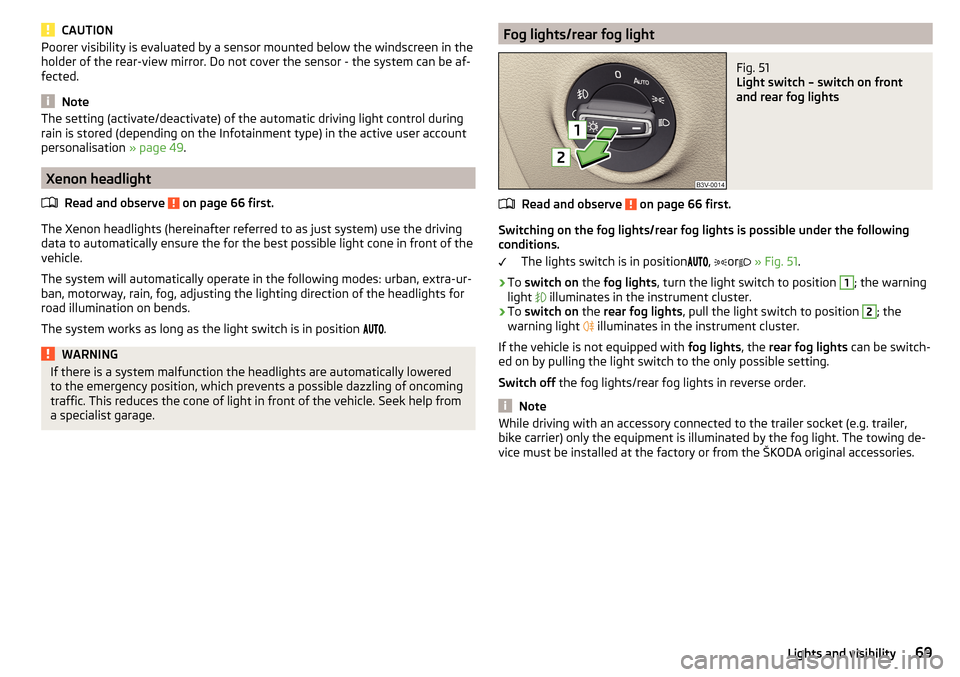
Light switch – switch on front
and rear fog lights
Read and observe on page 66 first.
Switching on the fog lights/rear fog lights is possible under the following
conditions.
The lights switch is in position ,
or
» Fig. 51 .
›
To switch on the fog lights , turn the light switch to position
1
; the warning
light illuminates in the instrument cluster.
›
To
switch on the rear fog lights , pull the light switch to position
2
; the
warning light illuminates in the instrument cluster.
If the vehicle is not equipped with fog lights, the rear fog lights can be switch-
ed on by pulling the light switch to the only possible setting.
Switch off the fog lights/rear fog lights in reverse order.
Note
While driving with an accessory connected to the trailer socket (e.g. trailer,
bike carrier) only the equipment is illuminated by the fog light. The towing de-
vice must be installed at the factory or from the ŠKODA original accessories.69Lights and visibility
Page 97 of 336

Long cargo channelFig. 106
Open the cover: from the passenger compartment / from the
luggage compartment
Read and observe
and on page 87 first.
After folding-up the rear armrest and cover, an opening in the seat backrest
becomes visible through which the through-loading bag with skis can be push-
ed.
›
To open from the passenger compartment , fold down the rear armrest
slightly » page 83 .
›
Pull handle
A
in the direction of arrow
1
and fold down the cover in the
direction of arrow
2
» Fig. 106 .
›
To open from the luggage compartment , push the securing tab
B
in the di-
rection of the arrow and fold the cover with the armrest forwards.
›
To close , fold the cover and the rear armrest upwards until the stop. This
should audibly click into place.
The cover must be secured after the closing process. Ensure that the red field
above the securing tab
B
is not visible.
WARNINGThe through-loading channel is only intended for transporting skis that are
placed in a properly secured, through-loading bag.Removable through-loading bagFig. 107
Tighten ribbon / secure through-loading bag
Read and observe
and on page 87 first.
The removable through-loading bag (hereinafter referred to as through-load-
ing bag) is used exclusively for transporting skis and poles (max. 4 pairs).
Stowing through-loading bag and skis
›
Fold the rear armrest and the cover in the seat backrest down-
wards » Fig. 106 on page 95 .
›
Place the empty through-loading bag in such a way that the end of the bag
with the zip is in the boot.
›
Place the skis with the tips facing to the front and the sticks with the tips
facing to the rear. into the through-loading bag and close the bag.
Securing through-loading bag and skis
›
Tighten the strap
A
around the skis in front of the bindings » Fig. 107. The
strap must hold the skis tight.
›
Fold the seat backrest a little forward » page 83.
›
Guide the securing strap
B
through the opening in the seat backrest around
the upper part of the seat backrest.
›
Then, fold the seat backrests back until the locking button clicks into place.
Check this by pulling on the seat backrest.
›
Insert the securing strap
B
into the lock
C
until it clicks into place.
WARNING■ The total weight of the skis which are transported must not exceed 24
kg.■
Always stow and secure the skis and the bag securely - otherwise there is
a risk of injury or accident!
95Practical features
Page 112 of 336

Positions of the variable loading floorFig. 139
Set variable loading floor to the upper position / variable loading
floor in the upper position
Fig. 140
Set variable loading floor to the lower position / variable loading
floor in the lower position
The variable loading floor can be set to the upper or lower position.
Set to the upper position
›
Lift the variable loading floor by the handle
A
» Fig. 139 about 20 cm high and
pull towards you.
›
Lift the loading floor to the height of the roll-up luggage compartment cover
in the direction of arrow
1
until you hear the clicking sound and press for-
ward.
The space below the variable loading floor can be used for stowing objects
such as the removed roll-up luggage compartment cover » page 105, the multi-
function pocket » page 108 etc.
The maximum permissible load of the variable loading floor is 75 kg. For the
transport of heavy loads, adjust the variable loading floor in the lower position
» Fig. 140 .
Set into the lower position›
Check that the area below the variable loading floor is empty.
›
Lift the variable loading floor by the handle
A
» Fig. 140 over the loading
edge in the direction of arrow
2
.
›
Pull the loading floor towards you in the direction of arrow
3
until it sinks to
the bottom position, and push forward.
Fold together / fold out the variable loading floor
Fig. 141
Fold up variable loading floor / folded variable cargo floor in the
upper position
›
To fold together , hold the variable loading floor on the handle
A
and lift in
the direction of arrow
1
» Fig. 141 .
›
Fold up the variable loading floor by moving it in the direction of the arrow
2
.
Folding out takes place in reverse order.
The variable loading floor is folded together / out in the same way in the upper
and lower position.
110Using the system
Page 192 of 336
›Press the
button, then tap on the function surface
→ Driver assistance →Speed warning:
.
For trailer towing , we recommend that you activate detection of road signs
relevant to trailers.›
Press the button, then tap on the function surface
Tap →
Driver assis-tance
→
Show road signs relevant to trailers
.
Route guidance
Introduction to the subject
A route is created by starting route guidance to a destination. Additional inter-
mediate destinations can be added to the route.
The route guidance takes place as follows
▶ Through graphical driving instructions in the Infotainment display screen and
in the display of the instrument cluster.
▶ With navigation announcements.
Infotainment tries to allow for continued guidance even if the navigation data
is incomplete or there is no data at all for the given area.
The route is recalculated each time if you ignore driving recommendations or
change the route.
CAUTION
The nav. announcements provided may vary from the actual situations, e.g.
due to out-of-date navigation data.
Destination details
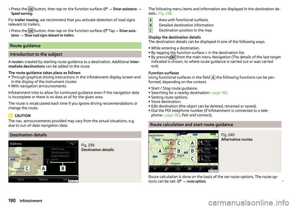
Fig. 239
Destination details
The following menu items and information are displayed in the destination de-
tails » Fig. 239 .
Area with functional surfaces
Detailed destination information
Destination position in the map
Display the destination details
The destination details can be displayed in one of the following ways.
▶ While entering a destination.
▶ By tapping the function surface
in the destination list.
▶ By pressing
from the main menu
Navigation (The details of the last target
indicated is shown, to where route guidance is carried out or was carried
out).
Function surfaces
Using functional surfaces in the field
A
the following functions can be per-
formed, depending on the context.
▶ Start / Stop route guidance.
▶ Searching for a nearby destination » page 182.
▶ Setting route options.
▶ Store destination.
▶ Edit destination (the object can be deleted, renamed or saved).
▶ Dial the POI telephone number (if Infotainment is connected to a tele-
phone » page 163 , Pair and connect ).
Route calculation and start route guidance
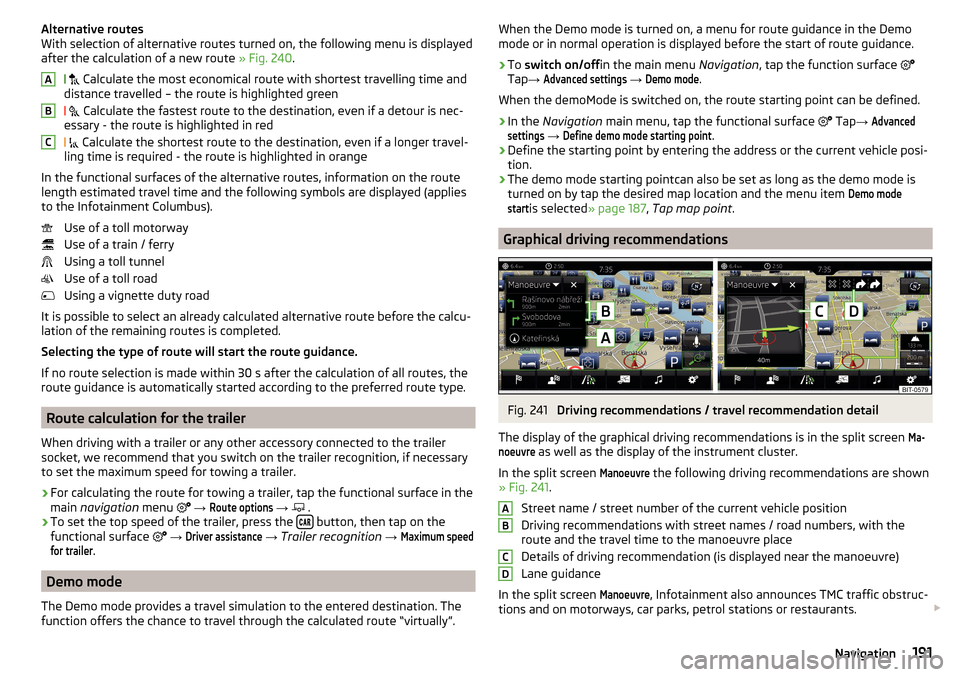
Fig. 240
Alternative routes
Route calculation is done on the basis of the set route options. The route op-
tions can be set:
→
route options
.
ABC190Infotainment
Page 193 of 336
Alternative routes
With selection of alternative routes turned on, the following menu is displayed
after the calculation of a new route » Fig. 240.
Calculate the most economical route with shortest travelling time and
distance travelled – the route is highlighted green
Calculate the fastest route to the destination, even if a detour is nec-
essary - the route is highlighted in red
Calculate the shortest route to the destination, even if a longer travel-
ling time is required - the route is highlighted in orange
In the functional surfaces of the alternative routes, information on the route length estimated travel time and the following symbols are displayed (applies
to the Infotainment Columbus).
Use of a toll motorway
Use of a train / ferry
Using a toll tunnel
Use of a toll road
Using a vignette duty road
It is possible to select an already calculated alternative route before the calcu-
lation of the remaining routes is completed.
Selecting the type of route will start the route guidance.
If no route selection is made within 30 s after the calculation of all routes, the
route guidance is automatically started according to the preferred route type.
Route calculation for the trailer
When driving with a trailer or any other accessory connected to the trailer
socket, we recommend that you switch on the trailer recognition, if necessary
to set the maximum speed for towing a trailer.
›
For calculating the route for towing a trailer, tap the functional surface in the
main navigation menu
→
Route options
→
.
›
To set the top speed of the trailer, press the button, then tap on the
functional surface
→
Driver assistance
→ Trailer recognition →
Maximum speedfor trailer
.
Demo mode
The Demo mode provides a travel simulation to the entered destination. The
function offers the chance to travel through the calculated route “virtually”.
ABCWhen the Demo mode is turned on, a menu for route guidance in the Demo
mode or in normal operation is displayed before the start of route guidance.›
To switch on/off in the main menu Navigation, tap the function surface
Tap →
Advanced settings
→
Demo mode
.
When the demoMode is switched on, the route starting point can be defined.
›
In the Navigation main menu, tap the functional surface
Tap →
Advancedsettings
→
Define demo mode starting point
.
›
Define the starting point by entering the address or the current vehicle posi-
tion.
›
The demo mode starting pointcan also be set as long as the demo mode is
turned on by tap the desired map location and the menu item
Demo modestart
is selected » page 187 , Tap map point .
Graphical driving recommendations
Fig. 241
Driving recommendations / travel recommendation detail
The display of the graphical driving recommendations is in the split screen
Ma-noeuvre
as well as the display of the instrument cluster.
In the split screen
Manoeuvre
the following driving recommendations are shown
» Fig. 241 .
Street name / street number of the current vehicle position
Driving recommendations with street names / road numbers, with the
route and the travel time to the manoeuvre place
Details of driving recommendation (is displayed near the manoeuvre)
Lane guidance
In the split screen
Manoeuvre
, Infotainment also announces TMC traffic obstruc-
tions and on motorways, car parks, petrol stations or restaurants.
ABCD191Navigation