towing SKODA SUPERB 2016 3.G / (B8/3V) Owner's Guide
[x] Cancel search | Manufacturer: SKODA, Model Year: 2016, Model line: SUPERB, Model: SKODA SUPERB 2016 3.G / (B8/3V)Pages: 336, PDF Size: 53.89 MB
Page 256 of 336

Permissible trailer load - Superb EstateEngineGearboxPermissible trailer weight, braked (kg)with gradients up to 12%.Permissible trailer weight, unbraked (kg) 1.4 l/92 kW TSIMG1600690
1.4 l/110 kW TSI ACT
MG1600700MG 4x41800750DSG16007201.4 l/110 kW TSIMG1600700DSG16007101.8 ltr./132 kW TSIMG1800740DSG18007502.0 l/162 kW TSIDSG20007502.0 l/206 kW TSIDSG 4x42200750
1.6 l/88 kW TDI CR
MG1500740MG (Green Line)1500750DSG1500750
2.0 l/110 kW TDI CR
MG2000750MG 4x42200750DSG20007502.0 l/130 kW TDI CRDSG2000750
2.0 l/140 kW TDI CR
MG2000750DSG2000750DSG 4x42200750WARNINGThe maximum vertical load and the maximum trailer load must not be ex-
ceeded - there is risk of accident!
Towing a trailer
Driving speed
For safety reasons, do not drive with the trailer any faster than 100 km/h
(when the towing vehicle is a passenger car of category M1) or 80 km/h (when
the towing vehicle is a truck of category N1).
Immediately reduce your speed as soon as even the slightest swaying of the
trailer is detected. Never attempt to stop the trailer from “swaying” by acceler-
ating.
Brakes
Apply the brakes in good time! If the trailer is fitted with a trailer brake, apply
the brakes gently at first, then brake firmly. This will avoid brake jolts resulting
from the trailer wheels locking.
On downhill sections shift down a gear in good time to also use the engine as
a brake. 254Driving
Page 257 of 336
WARNINGAlways drive particularly carefully with the trailer.
CAUTION
With frequent towing, the vehicle is excessively loaded so this must also be
checked between service intervals.
Anti-theft alarm system
The alarm is triggered if, with a vehicle with activated anti-theft alarm (herein-
after only warning system), the electrical connection to the trailer (accessory)
is interrupted.
Always switch off the anti-theft alarm system before a trailer (accessory) is
coupled or uncoupled » page 58.
Conditions for including a trailer (accessory) in the anti-theft alarm system. The vehicle is factory-fitted with an anti-theft alarm system and a towing
device.
The trailer (accessory) is electrically connected to the towing vehicle by
means of the trailer socket.
The electrical system of the vehicle and trailer (accessory) is functional.
The vehicle is locked and the anti-theft alarm system is activated.
The trailer (accessory) is not equipped with LED taillights.
255Towing device and trailer
Page 264 of 336

Vehicle compo-nentFacts of thematterRemedyWindows
and door mirrorsSoilingWash with clean water and dry using
the intended clothHeadlights/lightsSoilingSoft sponge and mild soap solution a)
Reversing cameraSoilingWash with clean water and dry with a
soft clothSnow / iceHand brush / de-icerDoor lock cylinderSnow / iceDe-icerWiper / wiper
bladesSoilingGlass cleaner, sponge or clothWheelsSoilingClear water, then coat with appropriate
conservation solutiona)
Mild soap solution = 2 tablespoons of natural soap to 1 litre of lukewarm water.
The jack is maintenance-free. If necessary, the moving parts of the jack should
be lubricated with a suitable lubricant.
The towing device is maintenance-free. Coat the ball head of the towing de-
vice with a suitable grease whenever necessary.
Protection of hollow spaces
All the hollow spaces on your vehicle which are at risk from corrosion are pro-
tected for life by a layer of protective wax applied in the factory.
If any small amount of wax flow out of the cavities at high temperatures, these
must be removed with a plastic scraper and the stains cleaned using a petrole-
um cleaner.
Underbody protection
The underside of your vehicle is already permanently protected by the factory
against chemical and mechanical influences.
We recommend having the protective coating underneath the vehicle and the
chassis checked — preferably before the beginning of winter and at the end of winter.
Product life of the films
Environmental influences (e.g. sunlight, humidity, air pollution, rockfall) affect
the life of the films. Films will age and become brittle – this is entirely normal:
this is not a fault.
Sunlight may also affect the strength of the film colour.
When transporting a load on the roof rack (e.g. roof box or similar), there is an
increased risk of film damage (e.g. of chipping from the secured load).
CAUTION
■ Vehicle paint
■ Damaged areas should be repaired as soon as possible.
■ Do not treat painted parts with or hard waxes.
■ Do not polish the paintwork in a dusty environment - risk of paint scratch-
es. ■ Do not apply any paint care products to door seals or window guides.■
Plastic parts
■ Do not use paint care products.
■
Chromed and anodised parts
■ Do not polish the chrome parts in a dusty environment - risk of surface
scratches.
■
Foils
The following instructions must be observed, otherwise there is a risk of foil
damage.
■ Do not clean with dirty cloths or sponges.
■ To remove ice and snow, do not use a scraper or other means.
■ Do not polish the foils
■ Do not use a pressure washer to clean the foils
■
Rubber seals
■ Do not treat the door seals and window guides with any products - the pro-
tective lacquer layer could be affected.
■
Windows and external mirror glass
■ Do not clean the inside of the windows with sharp objects - there is a risk
of damage to the filaments or glass antenna. ■ Do not use a cloth, which was used to polish the body - this could soil the
window and reduce visibility.
■
Headlights/lights ■ Do not dry off the headlights/lights, do not use sharp objects - there is a
risk of damage to the protective coating and subsequent cracking of the
headlight glass.
■
Reversing camera
The following instructions must be observed, otherwise there is a risk of
camera damage.
■ Do not remove snow / ice with warm / hot water.
■ To wash, never use a pressure washer or steam jet.
■ For cleaning, do not use abrasive cleaners.
262General Maintenance
Page 283 of 336
It is possible to store the reflective vests for the passengers on the rear seat in
the storage compartment in the rear doors.
Fire extinguisher
Fig. 330
Release the fire extinguisher
The fire extinguisher is attached by two straps in a bracket under the front
passenger's seat.
›
To remove the fire extinguisher, release the safety catches on the two belts
in the direction of arrow » Fig. 330and remove the fire extinguisher.
›
To secure , place the fire extinguisher back in the mount and secure with the
belts.
The Owner´s Manual is fitted next to the fire extinguisher.
Pay attention to the expiration date of the fire extinguisher. After this date,
the correct function of the device is not guaranteed.
WARNINGAlways properly secure the fire extinguisher, there is a risk of injury in the
event of sudden braking or a vehicle collision.Vehicle tool kitFig. 331
Vehicle tool kit
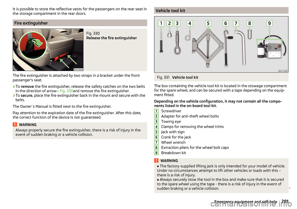
The box containing the vehicle tool kit is located in the stowage compartment for the spare wheel, and can be secured with a tape depending on the equip-
ment fitted.
Depending on the vehicle configuration, it may not contain all the compo-
nents listed in the on-board tool kit.
Screwdriver
Adapter for anti-theft wheel bolts
Towing eye
Clamps for removing the wheel trims
Jack with sign
Crank for the jack
Wheel wrench
Extraction pliers for the wheel bolt caps
Breakdown kit
WARNING■ The factory-supplied lifting jack is only intended for your model of vehicle.
Under no circumstances attempt to lift other vehicles or loads with this –
there is a risk of injury.■
Always securely stow the tool in the box and make sure that it is secured
to the spare wheel using the tape - there is a risk of injury in the event of
sudden braking or a vehicle collision.
123456789281Emergency equipment and self-help
Page 285 of 336
Removing /stowing the spare wheelFig. 332
Take out wheel
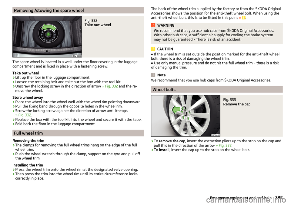
The spare wheel is located in a well under the floor covering in the luggage
compartment and is fixed in place with a fastening screw.
Take out wheel
›
Lift up the floor in the luggage compartment.
›
Loosen the retaining belt and take out the box with the tool kit.
›
Unscrew the locking screw in the direction of arrow » Fig. 332 and the re-
move the wheel.
Store wheel away
›
Place the wheel into the wheel well with the wheel rim pointing downward.
›
Pull the fixing band through the opposite holes in the wheel rim.
›
Screw the locking screw against the direction of arrow until it stops
» Fig. 332 .
›
Replace the box with the tool kit into the wheel and secure it with the tape.
›
Fold back the floor in the luggage compartment.
Full wheel trim
Removing the trim
›
The clamps for removing the full wheel trims hang on the edge of the full
wheel trim.
›
Push the wheel wrench through the clamp, support on the tyre and pull off
the wheel trim.
Installing the trim
›
Press the wheel trim onto the wheel rim at the designated valve opening.
›
Then press the trim into the wheel rim until its entire circumference locks
correctly in place.
The back of the wheel trim supplied by the factory or from the ŠKODA Original
Accessories shows the position for the anti-theft wheel bolt. When using the
anti-theft wheel bolt, this is to be fitted in this point »
.
WARNINGWe recommend that you use hub caps from ŠKODA Original Accessories.
With other hub caps, a sufficient air supply for cooling the brake system
may not be guaranteed - There is risk of an accident.
CAUTION
■ If the wheel trim is set outside the position marked for the anti-theft wheel
bolt, there is a risk of damaging the wheel trim.■
Use only manual pressure and do not hit the full wheel trim – there is a risk
of damaging the trim.
Note
We recommend that you use hub caps from ŠKODA Original Accessories.
Wheel bolts
Fig. 333
Remove the cap
›
To remove the cap , insert the extraction pliers up to the stop on the cap and
pull this in the direction of the arrow » Fig. 333.
›
To install , insert the cap up to the stop on the wheel bolt.
283Emergency equipment and self-help
Page 290 of 336
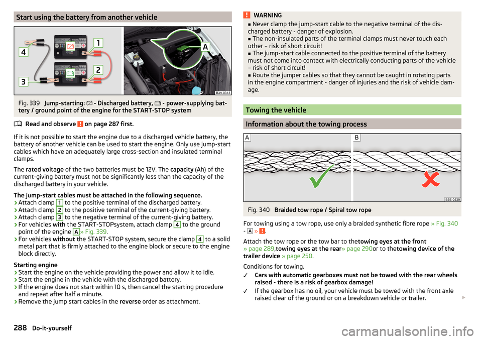
Start using the battery from another vehicleFig. 339
Jump-starting:
- Discharged battery,
- power-supplying bat-
tery / ground point of the engine for the START-STOP system
Read and observe
on page 287 first.
If it is not possible to start the engine due to a discharged vehicle battery, the
battery of another vehicle can be used to start the engine. Only use jump-start
cables which have an adequately large cross-section and insulated terminal
clamps.
The rated voltage of the two batteries must be 12V. The capacity (Ah) of the
current-giving battery must not be significantly less than the capacity of the
discharged battery in your vehicle.
The jump-start cables must be attached in the following sequence.
›
Attach clamp
1
to the positive terminal of the discharged battery.
›
Attach clamp
2
to the positive terminal of the current-giving battery.
›
Attach clamp
3
to the negative terminal of the current-giving battery.
›
For vehicles with the START-STOPsystem, attach clamp
4
to the ground
point of the engine
A
» Fig. 339 .
›
For vehicles without the START-STOP system, secure the clamp
4
to a solid
metal part that is firmly attached to the engine block or secure to the engine
block directly.
Starting engine
›
Start the engine on the vehicle providing the power and allow it to idle.
›
Start the engine in the vehicle with the discharged battery.
›
If the engine does not start within 10 s, then cancel the starting procedure
and repeat after half a minute.
›
Remove the jump start cables in the reverse order as attachment.
WARNING■
Never clamp the jump-start cable to the negative terminal of the dis-
charged battery - danger of explosion.■
The non-insulated parts of the terminal clamps must never touch each
other – risk of short circuit!
■
The jump-start cable connected to the positive terminal of the battery
must not come into contact with electrically conducting parts of the vehicle
– risk of short circuit!
■
Route the jumper cables so that they cannot be caught in rotating parts
in the engine compartment - danger of injuries and the risk of vehicle dam-
age.
Towing the vehicle
Information about the towing process
Fig. 340
Braided tow rope / Spiral tow rope
For towing using a tow rope, use only a braided synthetic fibre rope » Fig. 340
-
»
.
Attach the tow rope or the tow bar to the towing eyes at the front
» page 289 ,towing eyes at the rear » page 290or to thetowing device of the
trailer device » page 250 .
Conditions for towing. Cars with automatic gearboxes must not be towed with the rear wheels
raised - there is a risk of gearbox damage!
If the gearbox has no oil, your vehicle must be towed with the front axle
raised clear of the ground or on a breakdown vehicle or trailer.
288Do-it-yourself
Page 291 of 336
The maximum towing speed is 50 km/h.
The vehicle must be transported on a special breakdown vehicle or trailer
if it is not possible to tow in the vehicle in the way described or if the tow-
ing distance is greater than 50 km.
Driver of the tow vehicle›
On vehicles with manual transmission , engage gear slowly when starting.
›
On vehicles with automatic transmission , accelerate with particular care.
›
Only then approach correctly when the rope is taut.
Driver of the towed vehicle
›
If possible, the vehicle should be towed with the engine running. Operate the
brake booster and power steering only if the engine is running, otherwise
the brake pedal must be depressed more strongly and more power has to be
directed to the steering.
›
If it is not possible to start the engine, switch on the ignition so that the
steering wheel is not locked and so that the turn signal lights, windscreen
wipers and windscreen washer system can be used.
›
Take the vehicle out of gear or move the selector lever into position N if the
vehicle is fitted with an automatic gearbox.
›
Always keep the tow rope taut during the towing procedure.
WARNING■ Wound tow ropes must not be used for towing » Fig. 340- , the towing
eye may unscrew out of the vehicle - risk of accident.■
Ensure tow rope is not twisted - risk of accident.
CAUTION
■ Do not tow-start the engine – risk of damaging the engine! The battery from
another vehicle can be used as a jump-start aid » page 287, Jump-starting .■
In the case of off-road towing manoeuvres, for both vehicles there is the risk
that the fastening parts could be overloaded and damaged.
Note
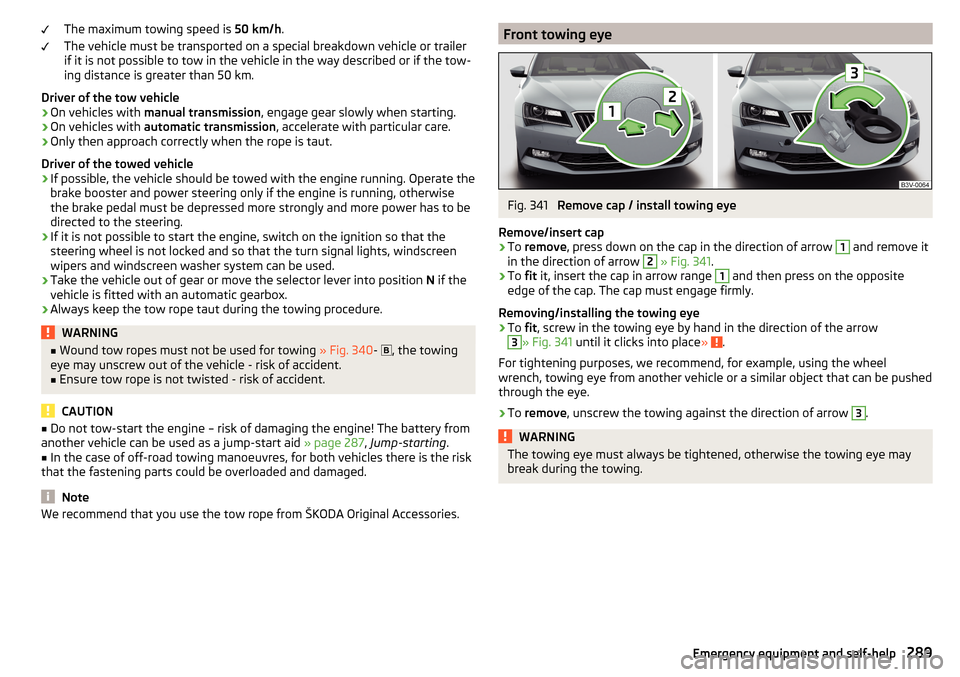
We recommend that you use the tow rope from ŠKODA Original Accessories.Front towing eyeFig. 341
Remove cap / install towing eye
Remove/insert cap
›
To remove , press down on the cap in the direction of arrow
1
and remove it
in the direction of arrow
2
» Fig. 341 .
›
To fit it, insert the cap in arrow range
1
and then press on the opposite
edge of the cap. The cap must engage firmly.
Removing/installing the towing eye
›
To fit, screw in the towing eye by hand in the direction of the arrow
3
» Fig. 341 until it clicks into place » .
For tightening purposes, we recommend, for example, using the wheel
wrench, towing eye from another vehicle or a similar object that can be pushed
through the eye.
›
To remove , unscrew the towing against the direction of arrow
3
.
WARNINGThe towing eye must always be tightened, otherwise the towing eye may
break during the towing.289Emergency equipment and self-help
Page 292 of 336
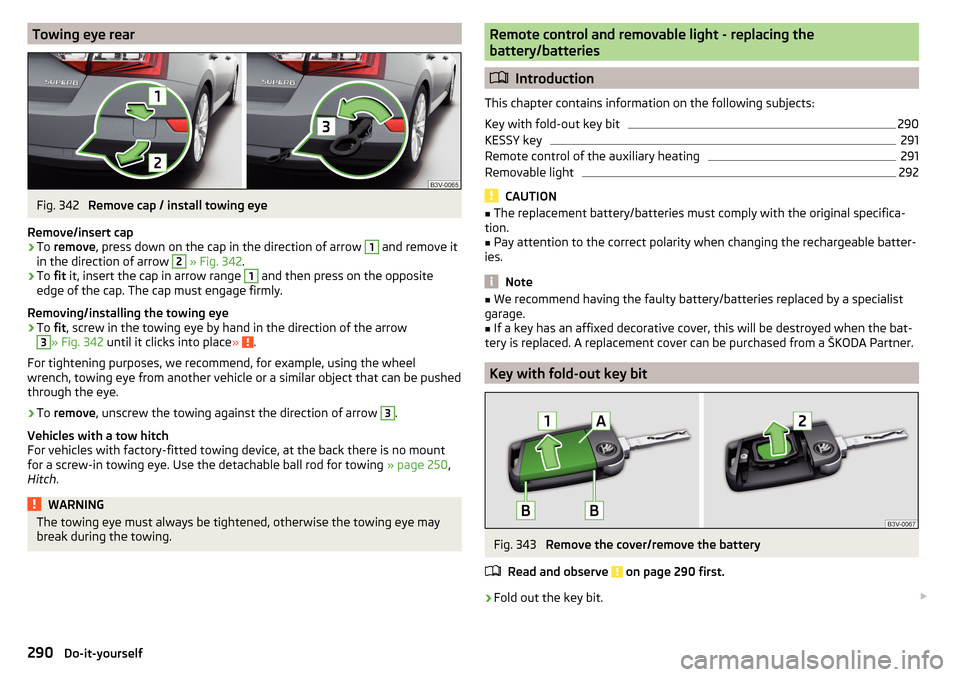
Towing eye rearFig. 342
Remove cap / install towing eye
Remove/insert cap
›
To remove , press down on the cap in the direction of arrow
1
and remove it
in the direction of arrow
2
» Fig. 342 .
›
To fit it, insert the cap in arrow range
1
and then press on the opposite
edge of the cap. The cap must engage firmly.
Removing/installing the towing eye
›
To fit, screw in the towing eye by hand in the direction of the arrow
3
» Fig. 342 until it clicks into place » .
For tightening purposes, we recommend, for example, using the wheel
wrench, towing eye from another vehicle or a similar object that can be pushed
through the eye.
›
To remove , unscrew the towing against the direction of arrow
3
.
Vehicles with a tow hitch
For vehicles with factory-fitted towing device, at the back there is no mount
for a screw-in towing eye. Use the detachable ball rod for towing » page 250,
Hitch .
WARNINGThe towing eye must always be tightened, otherwise the towing eye may
break during the towing.Remote control and removable light - replacing the
battery/batteries
Introduction
This chapter contains information on the following subjects:
Key with fold-out key bit
290
KESSY key
291
Remote control of the auxiliary heating
291
Removable light
292
CAUTION
■ The replacement battery/batteries must comply with the original specifica-
tion.■
Pay attention to the correct polarity when changing the rechargeable batter-
ies.
Note
■ We recommend having the faulty battery/batteries replaced by a specialist
garage.■
If a key has an affixed decorative cover, this will be destroyed when the bat-
tery is replaced. A replacement cover can be purchased from a ŠKODA Partner.
Key with fold-out key bit
Fig. 343
Remove the cover/remove the battery
Read and observe
on page 290 first.
›
Fold out the key bit.
290Do-it-yourself
Page 299 of 336
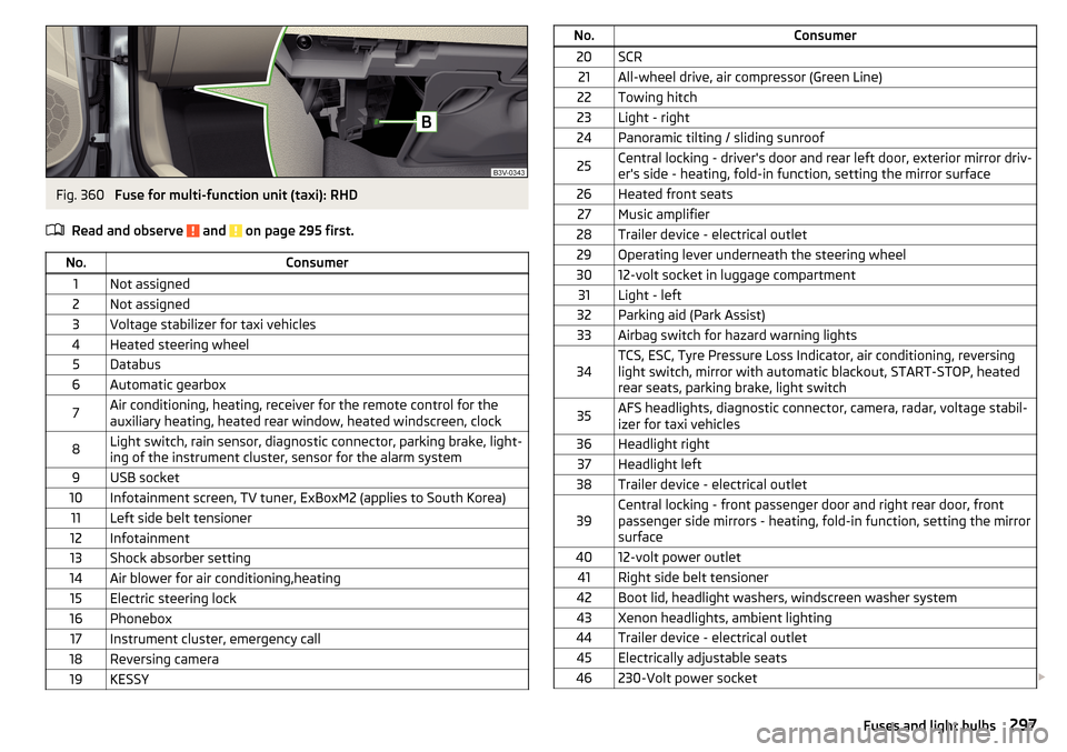
Fig. 360
Fuse for multi-function unit (taxi): RHD
Read and observe
and on page 295 first.
No.Consumer1Not assigned2Not assigned3Voltage stabilizer for taxi vehicles4Heated steering wheel5Databus6Automatic gearbox7Air conditioning, heating, receiver for the remote control for the
auxiliary heating, heated rear window, heated windscreen, clock8Light switch, rain sensor, diagnostic connector, parking brake, light-
ing of the instrument cluster, sensor for the alarm system9USB socket10Infotainment screen, TV tuner, ExBoxM2 (applies to South Korea)11Left side belt tensioner12Infotainment13Shock absorber setting14Air blower for air conditioning,heating15Electric steering lock16Phonebox17Instrument cluster, emergency call18Reversing camera19KESSYNo.Consumer20SCR21All-wheel drive, air compressor (Green Line)22Towing hitch23Light - right24Panoramic tilting / sliding sunroof25Central locking - driver's door and rear left door, exterior mirror driv-
er's side - heating, fold-in function, setting the mirror surface26Heated front seats27Music amplifier28Trailer device - electrical outlet29Operating lever underneath the steering wheel3012-volt socket in luggage compartment31Light - left32Parking aid (Park Assist)33Airbag switch for hazard warning lights34TCS, ESC, Tyre Pressure Loss Indicator, air conditioning, reversing
light switch, mirror with automatic blackout, START-STOP, heated
rear seats, parking brake, light switch35AFS headlights, diagnostic connector, camera, radar, voltage stabil-
izer for taxi vehicles36Headlight right37Headlight left38Trailer device - electrical outlet39Central locking - front passenger door and right rear door, front
passenger side mirrors - heating, fold-in function, setting the mirror
surface4012-volt power outlet41Right side belt tensioner42Boot lid, headlight washers, windscreen washer system43Xenon headlights, ambient lighting44Trailer device - electrical outlet45Electrically adjustable seats46230-Volt power socket 297Fuses and light bulbs
Page 306 of 336
The approved tyres and rim sizes for your vehicle are listed in the vehicle's
technical documentation (the so called COC document) and this also states the
declaration of conformity.
Type plate
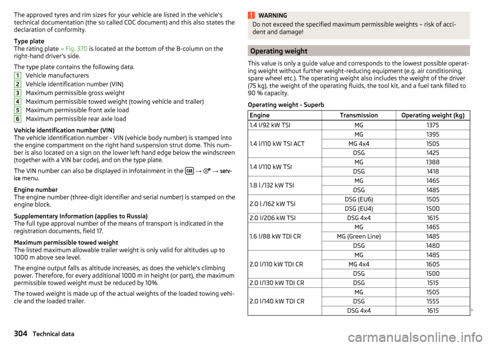
The rating plate » Fig. 370 is located at the bottom of the B-column on the
right-hand driver's side.
The type plate contains the following data. Vehicle manufacturers
Vehicle identification number (VIN)
Maximum permissible gross weight
Maximum permissible towed weight (towing vehicle and trailer)
Maximum permissible front axle load
Maximum permissible rear axle load
Vehicle identification number (VIN)
The vehicle identification number - VIN (vehicle body number) is stamped into
the engine compartment on the right hand suspension strut dome. This num-
ber is also located on a sign on the lower left hand edge below the windscreen
(together with a VIN bar code), and on the type plate.
The VIN number can also be displayed in Infotainment in the
→
→
serv-ice
menu.
Engine number
The engine number (three-digit identifier and serial number) is stamped on the
engine block.
Supplementary Information (applies to Russia)
The full type approval number of the means of transport is indicated in the
registration documents, field 17.
Maximum permissible towed weight
The listed maximum allowable trailer weight is only valid for altitudes up to
1000 m above sea level.
The engine output falls as altitude increases, as does the vehicle's climbing
power. Therefore, for every additional 1000 m in height (or part), the maximum
permissible towed weight must be reduced by 10%.
The towed weight is made up of the actual weights of the loaded towing vehi-
cle and the loaded trailer.
123456WARNINGDo not exceed the specified maximum permissible weights – risk of acci-
dent and damage!
Operating weight
This value is only a guide value and corresponds to the lowest possible operat-
ing weight without further weight-reducing equipment (e.g. air conditioning,
spare wheel etc.). The operating weight also includes the weight of the driver
(75 kg), the weight of the operating fluids, the tool kit, and a fuel tank filled to
90 % capacity.
Operating weight - Superb
EngineTransmissionOperating weight (kg)1.4 l/92 kW TSIMG1375
1.4 l/110 kW TSI ACT
MG1395MG 4x41505DSG14251.4 l/110 kW TSIMG1388DSG14181.8 l./132 kW TSIMG1465DSG14852.0 l./162 kW TSIDSG (EU6)1505DSG (EU4)15002.0 l/206 kW TSIDSG 4x41615
1.6 l/88 kW TDI CR
MG1465MG (Green Line)1485DSG1480
2.0 l/110 kW TDI CR
MG1485MG 4x41605DSG15002.0 l/130 kW TDI CRDSG1515
2.0 l/140 kW TDI CR
MG1505DSG1555DSG 4x41615 304Technical data