air condition SKODA SUPERB 2016 3.G / (B8/3V) Owner's Guide
[x] Cancel search | Manufacturer: SKODA, Model Year: 2016, Model line: SUPERB, Model: SKODA SUPERB 2016 3.G / (B8/3V)Pages: 336, PDF Size: 53.89 MB
Page 166 of 336
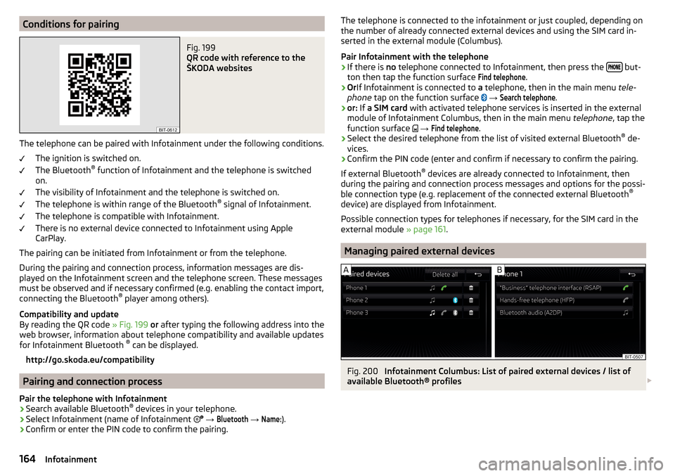
Conditions for pairingFig. 199
QR code with reference to the
ŠKODA websites
The telephone can be paired with Infotainment under the following conditions.
The ignition is switched on.
The Bluetooth ®
function of Infotainment and the telephone is switched
on.
The visibility of Infotainment and the telephone is switched on.
The telephone is within range of the Bluetooth ®
signal of Infotainment.
The telephone is compatible with Infotainment.
There is no external device connected to Infotainment using Apple
CarPlay.
The pairing can be initiated from Infotainment or from the telephone.
During the pairing and connection process, information messages are dis-
played on the Infotainment screen and the telephone screen. These messages must be observed and if necessary confirmed (e.g. enabling the contact import,
connecting the Bluetooth ®
player among others).
Compatibility and update
By reading the QR code » Fig. 199 or after typing the following address into the
web browser, information about telephone compatibility and available updates
for Infotainment Bluetooth ®
can be displayed.
http://go.skoda.eu/compatibility
Pairing and connection process
Pair the telephone with Infotainment
›
Search available Bluetooth ®
devices in your telephone.
›
Select Infotainment (name of Infotainment
→
Bluetooth
→
Name:
).
›
Confirm or enter the PIN code to confirm the pairing.
The telephone is connected to the infotainment or just coupled, depending on
the number of already connected external devices and using the SIM card in-
serted in the external module (Columbus).
Pair Infotainment with the telephone›
If there is no telephone connected to Infotainment, then press the but-
ton then tap the function surface
Find telephone
.
›
Or If Infotainment is connected to a telephone, then in the main menu tele-
phone tap on the function surface
→
Search telephone
.
›
or: If a SIM card with activated telephone services is inserted in the external
module of Infotainment Columbus, then in the main menu telephone, tap the
function surface
→
Find telephone
.
›
Select the desired telephone from the list of visited external Bluetooth ®
de-
vices.
›
Confirm the PIN code (enter and confirm if necessary to confirm the pairing.
If external Bluetooth ®
devices are already connected to Infotainment, then
during the pairing and connection process messages and options for the possi-
ble connection type (e.g. replacement of the connected external Bluetooth ®
device) are displayed from Infotainment.
Possible connection types for telephones if necessary, for the SIM card in the
external module » page 161.
Managing paired external devices
Fig. 200
Infotainment Columbus: List of paired external devices / list of
available Bluetooth® profiles
164Infotainment
Page 200 of 336
After entering, Infotainment calculates and provides an alternative route.
Enter traffic obstruction›
In the Navigation main menu, tap the function surface
→
Congestion ahead
.
›
Adjust the length of the traffic obstruction.
The traffic obstruction will be displayed in red in the map to the right along the
route.
Remove traffic obstruction
The traffic obstruction is removed from the route after completion of the route
guidance or can manually be removed as follows.
›
In the Navigation main menu, tap the function surface
→
Cancel "congest.ahead"
.
vehicle systems
CAR - Vehicle settings
Introduction to the subject
In the menu CAR travel data and information displayed on the vehicle and
some vehicle systems can be set.
Reset to factory settings
The factory reset be carried out in the
→
→
Factory settings
menu.
Note
Settings relating to the vehicle systems can only be made when the ignition is
switched on.
Main menu
Fig. 250
Function surfaces in the main
menu
›
Press the button The main menu appears with the following function sur-
faces » Fig. 250 .
Selecting the following menu points
▶
Convenience consumers
▶
Driving data
▶
DriveGreen
▶
Veh. status
Playback control - Radio / Media / TV tuner (applies to infotainment
Columbus)
Depending on the vehicle equipment with manual air conditioning: set-
ting the auxiliary heating and ventilation / Operation of heated windscreen
Vehicle system settings
198Infotainment
Page 204 of 336
Vehicles with automatic transmission
The engine is automatically switched off as soon as the vehicle comes to a
halt and the brake pedal is operated.
The engine is automatically started as soon as the accelerator pedal is de-
pressed or the brake pedal is released (with deactivated Auto Hold function).
Requirements for the system to function correctly
The following conditions must be met for the system to function correctly.
The driver's door is closed.
The driver has fastened the seat belt.
The driving speed was higher than 4 km/h after the last stop.
System status
The system status is shown in the display when the vehicle comes to a halt
» Fig. 253 .
The engine is switched off automatically; when moving off, the ignition
process will be initiated automatically.
The engine is not switched off automatically.
When stopping, the engine will not switch off for the following reasons,
among others. ▶ The engine temperature for the proper function of the system has not yet
been reached.
▶ The charge state of the vehicle battery is too low.
▶ The current consumption is too high.
▶ High air conditioning or heating output (high blower speed, big difference be-
tween the desired and actual interior temperature).
If the engine is shut down automatically and the system detects that the en- gine is required, such as when the brake pedal is pressed repeatedly, then the
system automatically starts the engine.
More information about the current system status can be displayed on the In-
fotainment screen in the menu
→
→
veh. status
.
If there is a system fault , the following message will appear in the display of
the instrument cluster. Seek help from a specialist garage.
Note■ If the driver's seat belt is removed for more than approx. 30 seconds or the
driver's door is opened during automatic stop mode, the engine will have to be
started manually.■
No automatic engine shut-down takes place when a vehicle with automatic
transmission is moving at low speed (e.g. during a traffic jam) and remains sta-
tionary after pressing the brake pedal lightly. Automatic engine shut-down
takes place if you press the brake pedal down with more force.
■
For vehicles with automatic transmission there is no automatic engine shut-
down when the system detects a manoeuvring action due to a large steering
angle.
Manually disable / enable system
Fig. 254
Button for the START-STOP sys-
tem
›
To deactivate/activate the system, press the
button » Fig. 254 .
When the system is deactivated, the symbol
illuminates in the button.
If the system is deactivated, it will be reactivated automatically after the igni-
tion has been switched off and on.
Note
If the system is deactivated when the engine is turned off automatically, then
the automatic start process takes place.202Driving
Page 205 of 336
Brakes and Parking
Introduction
This chapter contains information on the following subjects:
Electric parking brake
203
Auto Hold function
204
Parking
205
The wear of the brake pads is dependent on the operating conditions and driv-
ing style. Under difficult conditions (e.g. urban, sporty driving style) the condi-
tion of the brakes should also be checked by a specialist garage between the
service intervals.
The performance of the brakes can be delayed if the brakes are damp, iced up
in winter or if covered in a layer of salt . The brakes are cleaned and dried by
applying the brakes several times »
.
Corrosion on the brake discs and dirt on the brake pads occur if the vehicle has
been parked for a long period and if you do not make much use of the braking
system. The brakes are cleaned by applying the brakes several times »
.
Before travelling a long distance with a steep gradient , reduce speed and
shift into the next lowest gear. As a result, the braking effect of the engine will
be used, reducing the load on the brakes. If you do have to brake, this should
be carried out at intervals.
Emergency braking display - when an emergency braking is performed, the
automatic flashing of the brake lights are used to alert the traffic behind.
New brake pads must first be “worn in” because these do not initially have the
best possible braking effect. Drive especially carefully for the first 200 km or
so.
A too low brake fluid level can cause faults in the braking system , the warn-
ing light illuminates in the instrument cluster
» page 35,
Brake system
. If
the warning light does not illuminate and an extended stopping distance is re-
quired, then driving should be adapted according to the unknown cause of
fault and restricted braking effect - seek the assistance of a specialist garage
immediately.
The brake booster increases the pressure generated with the brake pedal. The
brake booster only operates when the engine is running.
WARNING■ Greater physical effort is required for braking when the engine is switch-
ed off – risk of accident!■
During the braking procedure on a vehicle with manual transmission,
when the vehicle is in gear and at low revs, press the clutch pedal. Other-
wise, the functionality of the brake system may be impaired – risk of acci-
dent!
■
Do not press the brake pedal if braking is now required. This causes the
brakes to overheat and can also result in a longer braking distance and ex-
cessive wear - risk of accident!
■
Braking for the purpose of drying and cleaning the brake discs should be
carried out only if the traffic conditions permit. Do not place any other road
users in jeopardy.
■
Recommendations for new brake pads have to be observed.
■
When stopping and parking, the parking brake should always be on, oth-
erwise the vehicle could move off - there is the risk of an accident!
■
If a front spoiler, full wheel trim, etc. is mounted retrospectively, it must
be ensured that the air supply to the front wheel brakes is not reduced.
Otherwise, the functionality of the brake system may be impaired – risk of
accident!
Electric parking brake
Fig. 255
Parking brake button
203Starting-off and Driving
Page 213 of 336
Avoiding damage to your vehicle
Introduction
This chapter contains information on the following subjects:
Driving Tips
211
Driving through water
211
Driving Tips
Only drive on such roads and in such terrain that match the vehicle parameters
» page 303 , Technical data as well as your driving skills.
The driver is always responsible for deciding whether the vehicle can handle
travelling in the given terrain.
WARNING■ Adjust the speed and driving style to the current visibility, weather, road
and traffic conditions. Too high a speed or an erroneous manoeuvre may
cause serious injury and damage to the vehicle.■
Combustible objects such as dry leaves or twigs caught under the base of
the vehicle could ignite on hot vehicle parts - risk of fire!
CAUTION
■ Pay attention to the ground clearance of the vehicle! When driving over ob-
jects which are larger than the ground clearance, the vehicle can get damaged.■
Any objects that get trapped under the vehicle floor must be removed as
soon as possible. These items can cause damage to the vehicle (e.g. on parts
of the fuel system or the brake system).
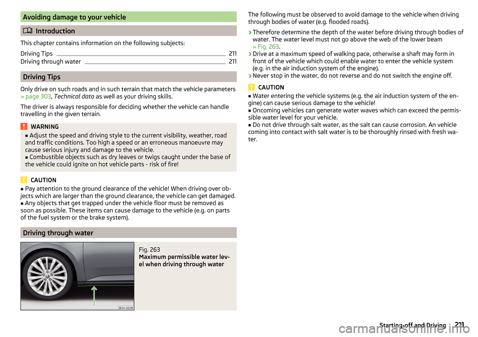
Driving through water
Fig. 263
Maximum permissible water lev-
el when driving through water
The following must be observed to avoid damage to the vehicle when driving
through bodies of water (e.g. flooded roads).›
Therefore determine the depth of the water before driving through bodies of
water. The water level must not go above the web of the lower beam
» Fig. 263 .
›
Drive at a maximum speed of walking pace, otherwise a shaft may form in
front of the vehicle which could enable water to enter the vehicle system
(e.g. in the air induction system of the engine).
›
Never stop in the water, do not reverse and do not switch the engine off.
CAUTION
■ Water entering the vehicle systems (e.g. the air induction system of the en-
gine) can cause serious damage to the vehicle!■
Oncoming vehicles can generate water waves which can exceed the permis-
sible water level for your vehicle.
■
Do not drive through salt water, as the salt can cause corrosion. An vehicle
coming into contact with salt water is to be thoroughly rinsed with fresh wa-
ter.
211Starting-off and Driving
Page 214 of 336
Assist systems
General information
Introduction
This chapter contains information on the following subjects:
Radar sensor
212WARNING■ The assistance systems only serve to support the driver and do not re-
lieve the driver of the responsibility for driving the vehicle.■
The increased safety provision, as well as the increased occupant protec-
tion provided by the assistance systems must not tempt you to take risks -
risk of accident!
■
Adjust the speed and driving style to the current visibility, weather, road
and traffic conditions.
■
The assistance systems have physical and system-related limitations. For
this reason, the driver may experience some undesired or delayed system
responses in certain situations. You should therefore always be alert and
ready to intervene!
■
Only enable, disable or set the assistance systems when you have the car
fully under control, in every traffic situation - risk of accident!
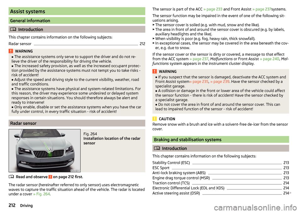
Radar sensor
Fig. 264
Installation location of the radar
sensor
Read and observe on page 212 first.
The radar sensor (hereinafter referred to only sensor) uses electromagnetic
waves to capture the traffic situation ahead of the vehicle. The radar is located
under a cover » Fig. 264.
The sensor is part of the ACC » page 233 and Front Assist » page 237systems.
The sensor function may be impaired in the event of one of the following sit-
uations arising. ▶ The sensor cover is soiled (e.g. with mud, snow and the like).
▶ The area in front of and around the sensor cover is obscured (e.g. by labels,
auxiliary headlights and the like(.
▶ When visibility is poor (e.g. fog, heavy rain, thick snowfall).
▶ In exceptional cases, the sensor may be covered in the area beneath the cov-
er, e.g. due to snow.
If the sensor cover or the sensor is dirty or covered, a message to that effect
from the ACC system » page 237, Malfunctions or Front Assist » page 240, Mal-
functions system appears in the instrument cluster display.WARNING■
If you suspect that the sensor is damaged, deactivate the ACC system and
Front Assist system » page 235, » page 239 . Have the sensor checked by a
specialist garage.■
A collision or damage in the front or lower area of the vehicle could affect
the sensor function - there is risk of accident! Have the sensor checked by
a specialist garage.
■
Do not cover the area in front of and around the sensor cover. This can
lead to impaired function of the sensor - risk of accident!
CAUTION
Remove snow with a brush and ice with a solvent-free de-icer from the sensor
cover.
Braking and stabilisation systems
Introduction
This chapter contains information on the following subjects:
Stability Control (ESC)
213
ESC Sport
213
Anti-lock braking system (ABS)
213
Engine drag torque control (MSR)
213
Traction control (TCS)
214
Electronic Differential Lock (EDL and XDS)
214
Active steering assist (DSR)
214
212Driving
Page 217 of 336
Multicollision brake (MCB)Read and observe
on page 213 first.
MCB helps to decrease speed after a collision by means of automatic braking
interventions and to stabilise the vehicle. This reduces the risk of a subse-
quent crash due to uncontrolled vehicle movement.
The automatic brake interventions can take place only if the following condi-
tions are met.
There was a front, side and rear-end collision of a certain severity.
The impact speed was greater than approx. 10 km/h.
The brakes, the ESL and other required electrical systems remain function-
al after impact.
The accelerator pedal is not actuated.
Trailer stabilisation system (TSA)
Read and observe
on page 213 first.
The TSA helps the combination stable in situations where the trailer sways
and then the whole trailer combination.
TSA brakes the individual wheels of the towing vehicle in order to damp the rocking motion of the entire vehicle combination.
The following conditions are required for the correct TSA function. The trailer was shipped from the factory or purchased from the ŠKODA
genuine accessories.
The trailer is electrically connected to the towing vehicle via the trailer
socket.
The parking aid is activated.
The speed is greater than 60 km/h.
Further information » page 250, Towing device and trailer .
Parking aid (ParkPilot)
Introduction
This chapter contains information on the following subjects:
Settings in Infotainment
216
Operation
216
Display in Infotainment screen
217
Activation / deactivation
217
Automatic system activation when moving forward
218
The parking aid (hereinafter referred to as system) uses acoustic signals or the
Infotainment screen when manoeuvring around obstacles in the vicinity of the
vehicle.
WARNING■ The general information relating to the use of assistance systems must
be observed » page 212, in section Introduction .■
Moving persons or objects may not be recognized by the system sensors.
■
Under certain circumstances, surfaces of certain objects and types of
clothing cannot reflect the system signals. There is a danger that such ob-
jects or people may not be recognised by the system sensors.
■
External noise sources may affect the signals of the system sensors.
There is a danger that obstacles may not be detected by the system sen-
sors.
■
Before reversing, you should satisfy yourself that there are no small ob-
stacle, such as a rock, thin post etc., in front or behind your vehicle. Such
obstacles may not be recognised by the system sensors.
CAUTION
■ Keep the system sensors » Fig. 266 on page 216 clean, snow-and ice-free
and do not cover with any objects of any kind, otherwise the system function-
ing may be impaired.■
Under adverse weather conditions (heavy rain, water vapour, very low or
high temperatures, etc.), the system function may be limited - “incorrect recog-
nition of obstacle”.
■
Accessories fitted to the vehicle rear, such as bicycle carriers, can impair the
system function.
215Assist systems
Page 221 of 336
WARNINGThe general information relating to the use of assistance systems must be
observed » page 212, in section Introduction .WARNING■
In the case of a collision or damage to the rear of the vehicle, the function
of the systems may be affected - risk of accident! Have the vehicle checked
by a specialist garage.■
Do not cover the sensor area - the function of the systems could be limi-
ted. ■ Remove snow, ice and such obstacles from the sensor environment im-
mediately.
WARNINGThe wizard for “blind spot”monitoring is limited by physical and system-re-
lated limits. Therefore, in the following situations the system can be de-
layed in drawing attention (or not at all) to a vehicle in the next land.■
When a vehicle is approaching at a very high speed.
■
When passing through a very sharp curve or a roundabout.
CAUTION
■ If a trailer or other accessory is to be connected to the trailer socket, then
the two systems are not available.■
In adverse weather conditions (heavy rain, water vapour, very low or high
temperatures, etc.), the system function may be limited - “failure to recognise
a vehicle”.
■
Accessories additionally installed on the vehicle rear, such as bicycle carriers,
can impair the system function.
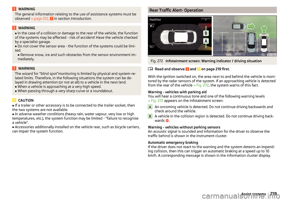
Rear Traffic Alert- OperationFig. 272
Infotainment screen: Warning indicator / driving situation
Read and observe
and on page 219 first.
With the ignition switched on, the area next to and behind the vehicle is moni-
tored by the radar sensors of the system. If an approaching vehicle is detected
from the rear of the vehicle » Fig. 272, the system warns of this fact.
Warning - vehicles with parking aid
You will hear a continuous tone and one of the following warning levels
» Fig. 272 appears on the Infotainment screen.
An oncoming vehicle is detected. Do not continue driving backwards and
check around the vehicle.
A vehicle in the collision region is detected. Do not continue driving back-
wards .
Warning - vehicles without parking sensors
An acoustic signal is sounded and information for the driver to observe the
traffic behind is shown in the instrument cluster.
Automatic emergency braking
If the driver does not react to the warning and the system detects an impend-
ing collision, then this can trigger an automatic braking at a speed up to 10
km/h. A corresponding message is shown in the information cluster display.
AB219Assist systems
Page 233 of 336
The automatic control interruption occurs if any of the following conditions
are met. ▶ The brake pedal is operated.
▶ When one of the brake assist systems (e.g. ESC) intervenes.
▶ By pressing the button D
» Fig. 289 .
▶ Through an airbag deployment.
WARNING■ Always deactivate the cruise control system after use to prevent the sys-
tem being switched on unintentionally.■
Control may only be resumed if the set speed is not too high for the cur-
rent traffic conditions.
Note
■ During control, speed can be increased by pressing the accelerator pedal. Re-
leasing the accelerator pedal will cause the speed to drop again to the set
speed.■
By pressing the button
D
» Fig. 289 during the regulation this is cancelled
and the Speed Limiter is activated.
Speed limiter
Introduction
This chapter contains information on the following subjects:
Function
231
Operation description - Variant with GRA
232
Operation description - Variant with ACC
232
The Speed Limiter limits the maximum driving speed to the set speed limit.
The speed limit can only be exceeded by depressing the accelerator pedal fully.
The condition in which the Speed Limiter prevents a potential set speed limit
excess is referred to as Regulation.
WARNINGThe general information relating to the use of assistance systems must be
observed » page 212, in section Introduction .FunctionFig. 290
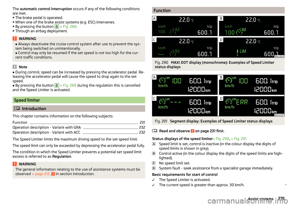
MAXI DOT display (monochrome): Examples of Speed Limiter
status displays
Fig. 291
Segment display: Examples of Speed Limiter status displays
Read and observe
on page 231 first.
Status displays of the speed limiter » Fig. 290, » Fig. 291
Speed limit is set, control is inactive (in the colour display the digits of
speed limits is shown in grey).
Control active (in the colour display the digits of the speed limits are high-
lighted).
No speed limit set.
System fault - seek assistance from a specialist garage immediately.
Basic requirements for start of control The Speed Limiter is activated.
The current speed is greater than approx. 30 km/h.
231Assist systems
Page 240 of 336
WARNING■Please take note of the general points relating to the use of assistance
systems » page 212, in section Introduction .■
The system does not respond to crossing or oncoming objects.
CAUTION
In case of failure of more than one brake light on the vehicle or on the electri-
cally connected trailer, the system becomes unavailable.
Settings in Infotainment
Read and observe
and on page 238 first.
›
Press the button, then tap on the function surface
→
Driver assistance
.
■ Front Assist (ambient traffic monitor. sys.) - Set the assistant for distance
monitoring to the vehicles ahead ■
Active
- Activate/deactivate the assistant
■
Advance warning
(Version 1) - Activate/deactivate advance warning
■
Advance warning
(Version 2) - Activating/deactivating and setting the distance
level at which a warning occurs
■
Display distance warning
- Activate/deactivate distance warnings
Operation
Read and observe
and on page 238 first.
The system support is provided in the following manner.▶ Alerts you about a dangerous proximity to the vehicle ahead.
▶ Warns you of an impending collision.
▶ Assists with a brake action triggered by the driver.
▶ If the driver fails to respond to a detected danger, an automatic braking ac-
tion is performed.
The system can work only if the following basic conditions are met. The system is activated.
TCS is activated » page 214.
The vehicle is travelling forwards at a speed of more than approx. 5 km/h.
Note
The system can be impaired or may not be available, for example when driving
in “sharp ”curves or with an ESC engagement » page 213.Distance warningFig. 299
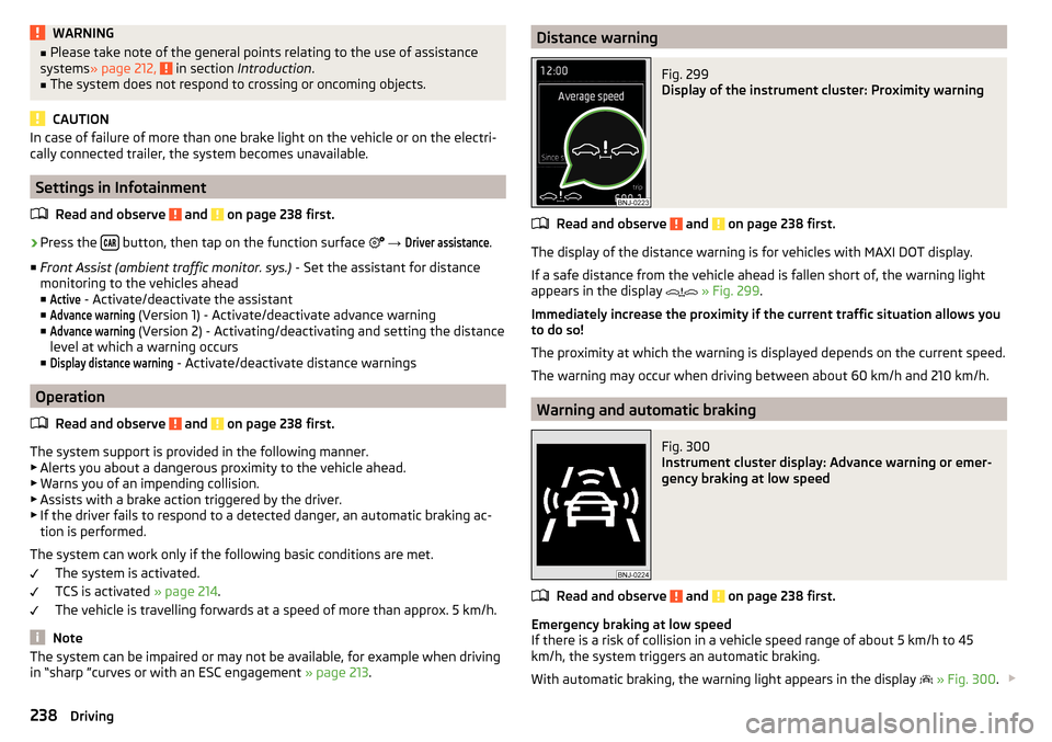
Display of the instrument cluster: Proximity warning
Read and observe and on page 238 first.
The display of the distance warning is for vehicles with MAXI DOT display.
If a safe distance from the vehicle ahead is fallen short of, the warning light
appears in the display
» Fig. 299 .
Immediately increase the proximity if the current traffic situation allows you
to do so!
The proximity at which the warning is displayed depends on the current speed.
The warning may occur when driving between about 60 km/h and 210 km/h.
Warning and automatic braking
Fig. 300
Instrument cluster display: Advance warning or emer-
gency braking at low speed
Read and observe and on page 238 first.
Emergency braking at low speed
If there is a risk of collision in a vehicle speed range of about 5 km/h to 45
km/h, the system triggers an automatic braking.
With automatic braking, the warning light appears in the display
» Fig. 300 .
238Driving