Emergency SKODA SUPERB 2016 3.G / (B8/3V) Owner's Guide
[x] Cancel search | Manufacturer: SKODA, Model Year: 2016, Model line: SUPERB, Model: SKODA SUPERB 2016 3.G / (B8/3V)Pages: 336, PDF Size: 53.89 MB
Page 248 of 336
Assistant for emergencies
Introduction
This chapter contains information on the following subjects:
Function
246
Operating conditions
246WARNING■ Please take note of the general points relating to the use of assistance
systems » page 212, in section Introduction .■
The system is intended for emergency situations when the driver is sud-
denly unable to take over the steering task. Therefore, never try to test out
the system - there is a risk of an accident!
Function
Read and observe
on page 246 first.
The assistant for emergencies (following known as system) detects inactivity
of the driver, which for example can be caused by a sudden loss of conscious-
ness. The system then performs measures as safely as possible to decelerate
the vehicle to a stop.
The system is only available for vehicles with Automatic transmission.
The assistant for emergencies is an extension of the systems Lane Assist
» page 243 and ACC » page 233 and works by using the functions of these two
systems.
For this reason, the chapters on System Lane Assist and ACC are to be read
carefully and the safety notes are to be observed.
System intervention
If the system detects the driver's inactivity, it draws attention to this fact by a beep and a message on the display of the instrument cluster. It keeps the ve-
hicle in its lane.
If the driver does not take over the steering even after a repeated warning,
the system automatically brakes the vehicle and after it has come to a stand-
still the parking brake switch on.
With automatic braking, the hazard warning system is switched on.
The automatic braking interventions can be cancelled by pressing the acceler-
ator pedal or by means of a steering intervention.
Operating conditions
Read and observe
on page 246 first.
The system can intervene when the following basic conditions are present. Lane Assist is activated and the boundary line is detected at least on one
side of the lane » page 243.
ACC is activated and the regulation » page 233 follows.
Traffic sign recognition
Introduction
This chapter contains information on the following subjects:
Settings in Infotainment
247
Operation
247
Additional display
248
Malfunction and information messages
248
The traffic sign recognition (following known as system) shows certain traffic
signs (e.g. speed limits) on the display of the instrument cluster and if necessa-
ry warns against excessive speeds.
WARNING■ Please take note of the general points relating to the use of assistance
systems » page 212, in section Introduction .■
Vertical traffic signs must always take precedence over the traffic signs
shown in the display. The driver is always responsible for correctly assess-
ing the traffic situation.
■
Speed specifications in the displayed road signs refer to the customary
speed units. For example, the display
the display can therefore refer to
km / h or mph, specific to the country.
246Driving
Page 267 of 336
Petrol and diesel refuellingFig. 315
Open fuel filler flap / unscrew tank cap / place the tank cap on
the fuel filler flap
Fig. 316
Fuel filler tube on vehicles with
diesel engines
Read and observe and on page 264 first.
Perform the refuelling under the following conditions.
The vehicle is unlocked.
The ignition is switched off.
The auxiliary heating and ventilation is switched off.
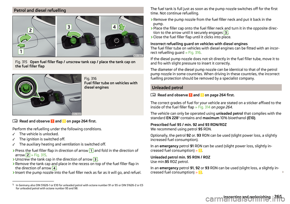
›
Press the fuel filler flap in direction of arrow
1
and fold in the direction of
arrow
2
» Fig. 315 .
›
Unscrew the tank cap in the direction of arrow
3
.
›
Remove the tank cap and place in the recess on top of the fuel filler flap in
the direction of arrow
4
.
›
Insert the pump nozzle into the fuel filler neck as far as it will go, and refuel.
The fuel tank is full just as soon as the pump nozzle switches off for the first
time. Not continue refuelling.›
Remove the pump nozzle from the fuel filler neck and put it back in the
pump.
›
Place the filler cap onto the fuel filler neck and turn it in the opposite direc-
tion to the arrow until it securely engages
3
.
›
Close the fuel filler flap until it clicks into place.
Incorrect refuelling guard on vehicles with diesel engines
The fuel filler tube on vehicles with diesel engines can be fitted with an incor-
rect refuelling guard » Fig. 316.
If the diesel pump nozzle does not sit directly in the fuel filler tube, move it to
and fro with slight pressure to insert it correctly.
The diameter of the diesel pump nozzle can be identical to that of the petrol
pump nozzle in some countries. When driving in these countries, the incorrect
fuelling protection should be removed by a specialist company.
Unleaded petrol
Read and observe
and on page 264 first.
The correct grades of fuel for your vehicle are stated on a sticker affixed to theinside of the fuel filler flap » Fig. 314 on page 264 .
The vehicle can only be operated using unleaded petrol that complies with the
standard EN 2281)
contains and maximum 10% bioethanol (E10).
Prescribed fuel 95 / min. 92 and 93 RON/ROZ
We recommend using petrol 95 RON.
Optionally, the petrol 92 or. 93 RON can be used (slight power loss, a slightly
increased fuel consumption).
In an emergency petrol 91 RON can be used (slight power loss, slightly in-
creased fuel consumption) »
.
Unleaded petrol min. 95 RON / ROZ
Use min. 95 ROZ petrol.
In an emergency petrol 91, 92 or 93 RON can be used (slight loss, a slightly in-
creased fuel consumption) »
.
1)
In Germany also DIN 51626-1 or E10 for unleaded petrol with octane number 91 or 95 or DIN 51626-2 or E5
for unleaded petrol with octane number 95 and 98.
265Inspecting and replenishing
Page 268 of 336

Prescribed petrol 98/(95) RON / ROZ
We recommend using petrol 98 RON.
Optionally, petrol 95 RON can be used (slight power loss, a slightly increased
fuel consumption).
In an emergency petrol 91, 92 or 93 RON can be used (slight loss, a slightly in-
creased fuel consumption) »
.
CAUTION
The following instructions must be observed, otherwise there is a risk of en-
gine damage and damage to the exhaust system.■
If gasoline is used which is lower than the prescribed octane number, then
continue driving at medium engine speeds and minimum engine load. Refuel
using petrol of the prescribed octane number as soon as possible.
■
Petrol with a lower Octane count than 91 should not even be used in an
emergency!
■
If a fuel other than unleaded fuel which complies to the above mentioned
standards (e.g. leaded petrol) is put in the tank by mistake, do not start the en-
gine or switch on the ignition.
CAUTION
Petrol additives (additives)■Unleaded petrol in accordance with the EN 228 standard 1)
meets all the con-
ditions for a smooth-running engine. Therefore, we recommend that you do
not add any fuel additives to the petrol - there is a risk of engine damage or
damage to the exhaust system.■
The following additives and auxiliary products may not be used - there is a
risk of engine damage or damage to the exhaust system! ■ Additives with metal components (metallic additives), in particular with
manganese and iron content. ■ Fuels with metallic content (e.g. LRP - lead replacement petrol).
Note■ Unleaded petrol that has a higher octane number than that required by the
engine can be used without limitations.■
The use of petrol with an octane rating higher than 95 RON in does not re-
sult in either a noticeable increase in power nor lower fuel consumption in ve-
hicles for which unleaded petrol 95/min 92 or 93 RON is specified.
■
On vehicles using prescribed petrol of min. 95 RON, the use of petrol with a
higher octane number than 95 RON can increase the power and reduce fuel
consumption.
Diesel fuel
Read and observe
and on page 264 first.
The correct grades of fuel for your vehicle are stated on a sticker affixed to theinside of the fuel filler flap » Fig. 314 on page 264 .
The vehicle can only be operated using diesel fuel that complies with the
standard EN 5902)
and contains a maximum 7% biodiesel (B7)3)
.
Operating under different weather conditions
Use only diesel in accordance with the current or expected weather conditions.
Ask the petrol station personnel whether the diesel fuel offered corresponds
to these conditions.
CAUTION
The following instructions must be observed, otherwise there is a risk of en-
gine damage and damage to the exhaust system.■
If a different fuel other than diesel fuel, which complies to the above men-
tioned standards (e.g. petrol) is put into the tank, do not start the engine or
switch on the ignition!
■
The biofuel RME must not be used!
1)
In Germany also DIN 51626-1 or E10 for unleaded petrol with octane number 91 or 95 or DIN 51626-2 or E5
for unleaded petrol with octane number 95 and 98.
2)
In Germany DIN 51628, in Austria ÖNORM C 1590, in Russia GOST R 52368-2005 / EN 590: 2004, in India
IS 1460 / Bharat IV or in an emergency IS 1460 / Bharat III.
3)
In Germany according to the DIN 52638 standard, in Austria ÖNORM C 1590, in France EN 590.
266General Maintenance
Page 280 of 336
WARNING■Change when they are worn down to the wear indicators at the latest -
risk of accident.■
Improper wheel alignment affects the driving behaviour - there is an acci-
dent.
■
Unusual vibrations or “pulling” of the vehicle to one side could be a sign
of tyre damage. Reduce speed and stop! If no tyre damage is evident, seek
the assistance of a specialist garage.
Spare wheel
Use the emergency spare wheel only to reach the nearest specialist garage, as
it is not intended for permanent use .
A warning label is displayed on the rim of the temporary spare wheel.
Please note the following if you intend to use the temporary spare wheel. ▶ Do not cover the signs.
▶ Be particularly observant when driving.
▶ Inflate the temporary spare wheel to the maximum inflation pressure for the
vehicle » page 277 (the prescribed tyre pressure of the spare wheel R 18 is
4.2 bar).
In vehicles with tyre pressure monitoring, save the tyre pressure values in the
system » page 249 .
WARNING■
Never drive with more than one spare wheel mounted!■When driving with the temporary spare wheel at full throttle acceleration,
avoid sharp braking and fast cornering.■
Do not use snow chains on the temporary spare wheel.
■
Observe instructions on the warning sign of the emergency wheel.
Tyre marking
Explanation of tyre markings - e.g. 215/60 R 16 95 V
215Tyre width in mm60Height/width ratio in %RCode letter for the type of tyre – Radial16Diameter of wheel in inches95load indexVSpeed symbol
Load index - indicates the maximum permissible load for each individual tyre
load index919293949596979899Load
(In kg)615630650670690710730750775
Speed symbol - indicates the maximum permissible speed for a vehicle fitted
with tyres in the category concerned
speed
symbolMTUHVWYMaximum speed
(in km/h)130190200210240270300WARNINGNever exceed the maximum permissible load bearing capacity and speed
for the tyres fitted – There is a risk of accident.
Operating in winter conditions
All-year (or “winter”) tyres
All-season or “winter”tyres (indicated by an M+S or a mountain peak/snow-
flake symbol ) to improve the performance of the vehicle in winter condi-
tions.
For the best possible handling, use all-season or “winter” tyres on all four
wheels with a minimum tread depth of 4 mm.
If using “winter” tyres, fit the summer tyres on again in good time as they pro-
vide better handling properties, a shorter braking distance, less tyre noise, and
reduced tyre wear on roads which are free of snow and ice as well as at tem-
peratures above 7 °C.
278General Maintenance
Page 282 of 336

Do-it-yourself
Emergency equipment and self-help
Emergency equipment
Introduction
This chapter contains information on the following subjects:
Placement of the first aid kit and warning triangle
280
Placement of reflective vest
280
Fire extinguisher
281
Vehicle tool kit
281
Placement of the first aid kit and warning triangle
Fig. 327
Placement of first aid kits and warning triangle: Variant 1 / Loos-
en warning triangle
Fig. 328
Placement of the first-aid kit and
the warning triangle: Variant 2
The following information applies for the first aid kit and warning triangle from
the ŠKODA Original Accessories.
Placing the first-aid kit
The first-aid kit can be attached by a strap to the right-hand side of the boot
» Fig. 327 or » Fig. 328 .
Depending on the equipment fitted, in the same place a storage compartment
may be located in which the first aid kit can be stowed.
Placing of the warning triangle - variant 1
The warning triangle can be inserted into the recess under the loading edge
and secured with the fastener tape » Fig. 327.›
To release , press the clasp on the tape in the direction of arrow
1
fold open
the belt
A
in the direction of arrow
2
» Fig. 327 .
›
To secure , fold up the belt
A
against the arrow direction
2
until it locks in-
to place.
Warning triangle – version 2
The warning triangle can be stored in the recess under the loading edge
» Fig. 328 . Before it is taken out, the floor covering of the luggage compart-
ment must be raised.
WARNINGProperly secure the first aid kit and the warning triangle, or there is a risk of
injury in the event of sudden braking or a vehicle collision.
Placement of reflective vest
Fig. 329
Stowage compartment for the
reflective vest in the front door
The reflective vest can be stowed in the storage compartment
A
inside the
storage compartment of the front door » Fig. 329.
280Do-it-yourself
Page 283 of 336
It is possible to store the reflective vests for the passengers on the rear seat in
the storage compartment in the rear doors.
Fire extinguisher
Fig. 330
Release the fire extinguisher
The fire extinguisher is attached by two straps in a bracket under the front
passenger's seat.
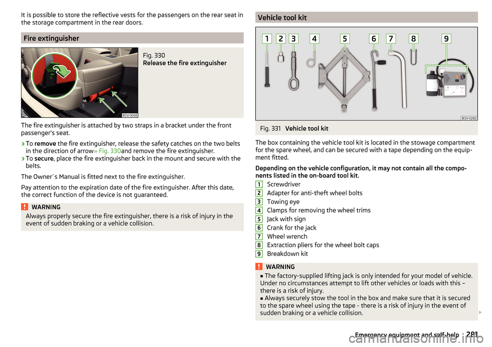
›
To remove the fire extinguisher, release the safety catches on the two belts
in the direction of arrow » Fig. 330and remove the fire extinguisher.
›
To secure , place the fire extinguisher back in the mount and secure with the
belts.
The Owner´s Manual is fitted next to the fire extinguisher.
Pay attention to the expiration date of the fire extinguisher. After this date,
the correct function of the device is not guaranteed.
WARNINGAlways properly secure the fire extinguisher, there is a risk of injury in the
event of sudden braking or a vehicle collision.Vehicle tool kitFig. 331
Vehicle tool kit
The box containing the vehicle tool kit is located in the stowage compartment for the spare wheel, and can be secured with a tape depending on the equip-
ment fitted.
Depending on the vehicle configuration, it may not contain all the compo-
nents listed in the on-board tool kit.
Screwdriver
Adapter for anti-theft wheel bolts
Towing eye
Clamps for removing the wheel trims
Jack with sign
Crank for the jack
Wheel wrench
Extraction pliers for the wheel bolt caps
Breakdown kit
WARNING■ The factory-supplied lifting jack is only intended for your model of vehicle.
Under no circumstances attempt to lift other vehicles or loads with this –
there is a risk of injury.■
Always securely stow the tool in the box and make sure that it is secured
to the spare wheel using the tape - there is a risk of injury in the event of
sudden braking or a vehicle collision.
123456789281Emergency equipment and self-help
Page 285 of 336
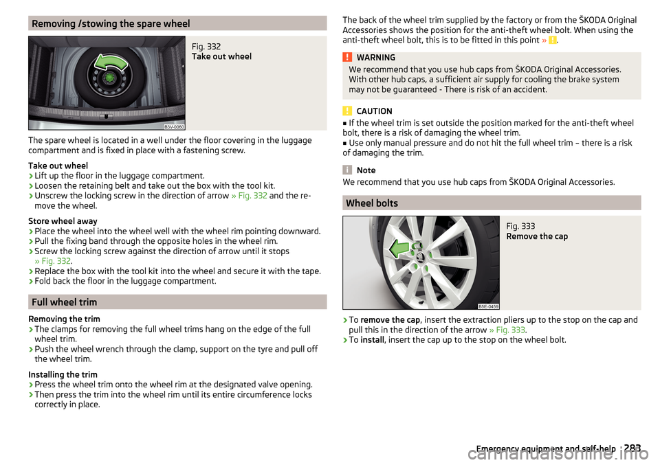
Removing /stowing the spare wheelFig. 332
Take out wheel
The spare wheel is located in a well under the floor covering in the luggage
compartment and is fixed in place with a fastening screw.
Take out wheel
›
Lift up the floor in the luggage compartment.
›
Loosen the retaining belt and take out the box with the tool kit.
›
Unscrew the locking screw in the direction of arrow » Fig. 332 and the re-
move the wheel.
Store wheel away
›
Place the wheel into the wheel well with the wheel rim pointing downward.
›
Pull the fixing band through the opposite holes in the wheel rim.
›
Screw the locking screw against the direction of arrow until it stops
» Fig. 332 .
›
Replace the box with the tool kit into the wheel and secure it with the tape.
›
Fold back the floor in the luggage compartment.
Full wheel trim
Removing the trim
›
The clamps for removing the full wheel trims hang on the edge of the full
wheel trim.
›
Push the wheel wrench through the clamp, support on the tyre and pull off
the wheel trim.
Installing the trim
›
Press the wheel trim onto the wheel rim at the designated valve opening.
›
Then press the trim into the wheel rim until its entire circumference locks
correctly in place.
The back of the wheel trim supplied by the factory or from the ŠKODA Original
Accessories shows the position for the anti-theft wheel bolt. When using the
anti-theft wheel bolt, this is to be fitted in this point »
.
WARNINGWe recommend that you use hub caps from ŠKODA Original Accessories.
With other hub caps, a sufficient air supply for cooling the brake system
may not be guaranteed - There is risk of an accident.
CAUTION
■ If the wheel trim is set outside the position marked for the anti-theft wheel
bolt, there is a risk of damaging the wheel trim.■
Use only manual pressure and do not hit the full wheel trim – there is a risk
of damaging the trim.
Note
We recommend that you use hub caps from ŠKODA Original Accessories.
Wheel bolts
Fig. 333
Remove the cap
›
To remove the cap , insert the extraction pliers up to the stop on the cap and
pull this in the direction of the arrow » Fig. 333.
›
To install , insert the cap up to the stop on the wheel bolt.
283Emergency equipment and self-help
Page 287 of 336
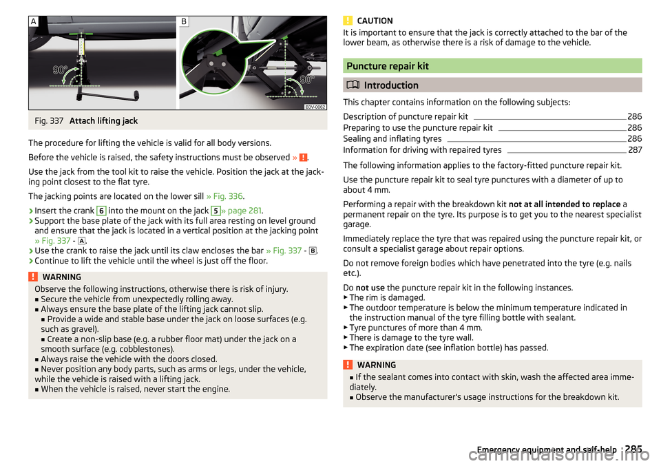
Fig. 337
Attach lifting jack
The procedure for lifting the vehicle is valid for all body versions.
Before the vehicle is raised, the safety instructions must be observed »
.
Use the jack from the tool kit to raise the vehicle. Position the jack at the jack-
ing point closest to the flat tyre.
The jacking points are located on the lower sill » Fig. 336.
›
Insert the crank
6
into the mount on the jack
5
» page 281 .
›
Support the base plate of the jack with its full area resting on level ground
and ensure that the jack is located in a vertical position at the jacking point
» Fig. 337 -
.
›
Use the crank to raise the jack until its claw encloses the bar
» Fig. 337 -
.
›
Continue to lift the vehicle until the wheel is just off the floor.
WARNINGObserve the following instructions, otherwise there is risk of injury.■Secure the vehicle from unexpectedly rolling away.■
Always ensure the base plate of the lifting jack cannot slip.
■ Provide a wide and stable base under the jack on loose surfaces (e.g.
such as gravel). ■ Create a non-slip base (e.g. a rubber floor mat) under the jack on a
smooth surface (e.g. cobblestones).
■
Always raise the vehicle with the doors closed.
■
Never position any body parts, such as arms or legs, under the vehicle,
while the vehicle is raised with a lifting jack.
■
When the vehicle is raised, never start the engine.
CAUTIONIt is important to ensure that the jack is correctly attached to the bar of the
lower beam, as otherwise there is a risk of damage to the vehicle.
Puncture repair kit
Introduction
This chapter contains information on the following subjects:
Description of puncture repair kit
286
Preparing to use the puncture repair kit
286
Sealing and inflating tyres
286
Information for driving with repaired tyres
287
The following information applies to the factory-fitted puncture repair kit.
Use the puncture repair kit to seal tyre punctures with a diameter of up to
about 4 mm.
Performing a repair with the breakdown kit not at all intended to replace a
permanent repair on the tyre. Its purpose is to get you to the nearest specialist
garage.
Immediately replace the tyre that was repaired using the puncture repair kit, or
consult a specialist garage about repair options.
Do not remove foreign bodies which have penetrated into the tyre (e.g. nails etc.).
Do not use the puncture repair kit in the following instances.
▶ The rim is damaged.
▶ The outdoor temperature is below the minimum temperature indicated in
the instruction manual of the tyre filling bottle with sealant.
▶ Tyre punctures of more than 4 mm.
▶ There is damage to the tyre wall.
▶ The expiration date (see inflation bottle) has passed.
WARNING■ If the sealant comes into contact with skin, wash the affected area imme-
diately.■
Observe the manufacturer's usage instructions for the breakdown kit.
285Emergency equipment and self-help
Page 289 of 336
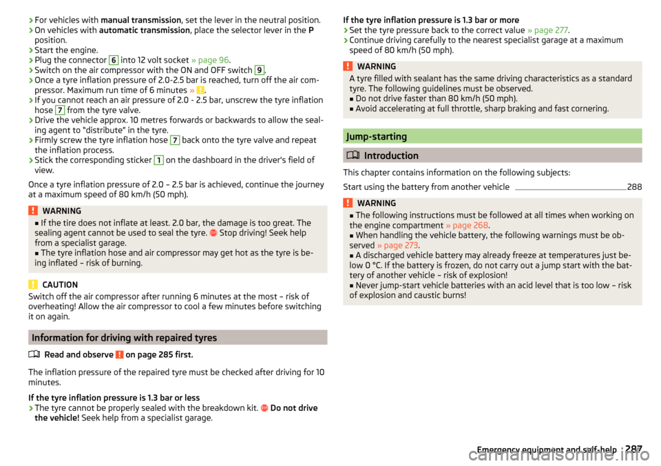
›For vehicles with
manual transmission , set the lever in the neutral position.›On vehicles with automatic transmission , place the selector lever in the P
position.›
Start the engine.
›
Plug the connector
6
into 12 volt socket » page 96.
›
Switch on the air compressor with the ON and OFF switch
9
.
›
Once a tyre inflation pressure of 2.0-2.5 bar is reached, turn off the air com-
pressor. Maximum run time of 6 minutes » .
›
If you cannot reach an air pressure of 2.0 - 2.5 bar, unscrew the tyre inflation
hose
7
from the tyre valve.
›
Drive the vehicle approx. 10 metres forwards or backwards to allow the seal-
ing agent to “distribute” in the tyre.
›
Firmly screw the tyre inflation hose
7
back onto the tyre valve and repeat
the inflation process.
›
Stick the corresponding sticker
1
on the dashboard in the driver's field of
view.
Once a tyre inflation pressure of 2.0 – 2.5 bar is achieved, continue the journey
at a maximum speed of 80 km/h (50 mph).
WARNING■ If the tire does not inflate at least. 2.0 bar, the damage is too great. The
sealing agent cannot be used to seal the tyre. Stop driving! Seek help
from a specialist garage.■
The tyre inflation hose and air compressor may get hot as the tyre is be-
ing inflated – risk of burning.
CAUTION
Switch off the air compressor after running 6 minutes at the most – risk of
overheating! Allow the air compressor to cool a few minutes before switching
it on again.
Information for driving with repaired tyres
Read and observe
on page 285 first.
The inflation pressure of the repaired tyre must be checked after driving for 10
minutes.
If the tyre inflation pressure is 1.3 bar or less
›
The tyre cannot be properly sealed with the breakdown kit.
Do not drive
the vehicle! Seek help from a specialist garage.
If the tyre inflation pressure is 1.3 bar or more›Set the tyre pressure back to the correct value » page 277.›
Continue driving carefully to the nearest specialist garage at a maximum
speed of 80 km/h (50 mph).
WARNINGA tyre filled with sealant has the same driving characteristics as a standard
tyre. The following guidelines must be observed.■
Do not drive faster than 80 km/h (50 mph).
■
Avoid accelerating at full throttle, sharp braking and fast cornering.
Jump-starting
Introduction
This chapter contains information on the following subjects:
Start using the battery from another vehicle
288WARNING■ The following instructions must be followed at all times when working on
the engine compartment » page 268.■
When handling the vehicle battery, the following warnings must be ob-
served » page 273 .
■
A discharged vehicle battery may already freeze at temperatures just be-
low 0 °C. If the battery is frozen, do not carry out a jump start with the bat-
tery of another vehicle – risk of explosion!
■
Never jump-start vehicle batteries with an acid level that is too low – risk
of explosion and caustic burns!
287Emergency equipment and self-help
Page 291 of 336
The maximum towing speed is 50 km/h.
The vehicle must be transported on a special breakdown vehicle or trailer
if it is not possible to tow in the vehicle in the way described or if the tow-
ing distance is greater than 50 km.
Driver of the tow vehicle›
On vehicles with manual transmission , engage gear slowly when starting.
›
On vehicles with automatic transmission , accelerate with particular care.
›
Only then approach correctly when the rope is taut.
Driver of the towed vehicle
›
If possible, the vehicle should be towed with the engine running. Operate the
brake booster and power steering only if the engine is running, otherwise
the brake pedal must be depressed more strongly and more power has to be
directed to the steering.
›
If it is not possible to start the engine, switch on the ignition so that the
steering wheel is not locked and so that the turn signal lights, windscreen
wipers and windscreen washer system can be used.
›
Take the vehicle out of gear or move the selector lever into position N if the
vehicle is fitted with an automatic gearbox.
›
Always keep the tow rope taut during the towing procedure.
WARNING■ Wound tow ropes must not be used for towing » Fig. 340- , the towing
eye may unscrew out of the vehicle - risk of accident.■
Ensure tow rope is not twisted - risk of accident.
CAUTION
■ Do not tow-start the engine – risk of damaging the engine! The battery from
another vehicle can be used as a jump-start aid » page 287, Jump-starting .■
In the case of off-road towing manoeuvres, for both vehicles there is the risk
that the fastening parts could be overloaded and damaged.
Note
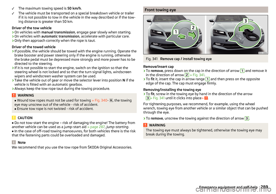
We recommend that you use the tow rope from ŠKODA Original Accessories.Front towing eyeFig. 341
Remove cap / install towing eye
Remove/insert cap
›
To remove , press down on the cap in the direction of arrow
1
and remove it
in the direction of arrow
2
» Fig. 341 .
›
To fit it, insert the cap in arrow range
1
and then press on the opposite
edge of the cap. The cap must engage firmly.
Removing/installing the towing eye
›
To fit, screw in the towing eye by hand in the direction of the arrow
3
» Fig. 341 until it clicks into place » .
For tightening purposes, we recommend, for example, using the wheel
wrench, towing eye from another vehicle or a similar object that can be pushed
through the eye.
›
To remove , unscrew the towing against the direction of arrow
3
.
WARNINGThe towing eye must always be tightened, otherwise the towing eye may
break during the towing.289Emergency equipment and self-help