Emergency SKODA SUPERB 2016 3.G / (B8/3V) User Guide
[x] Cancel search | Manufacturer: SKODA, Model Year: 2016, Model line: SUPERB, Model: SKODA SUPERB 2016 3.G / (B8/3V)Pages: 336, PDF Size: 53.89 MB
Page 57 of 336
Locking / unlocking - KESSYFig. 35
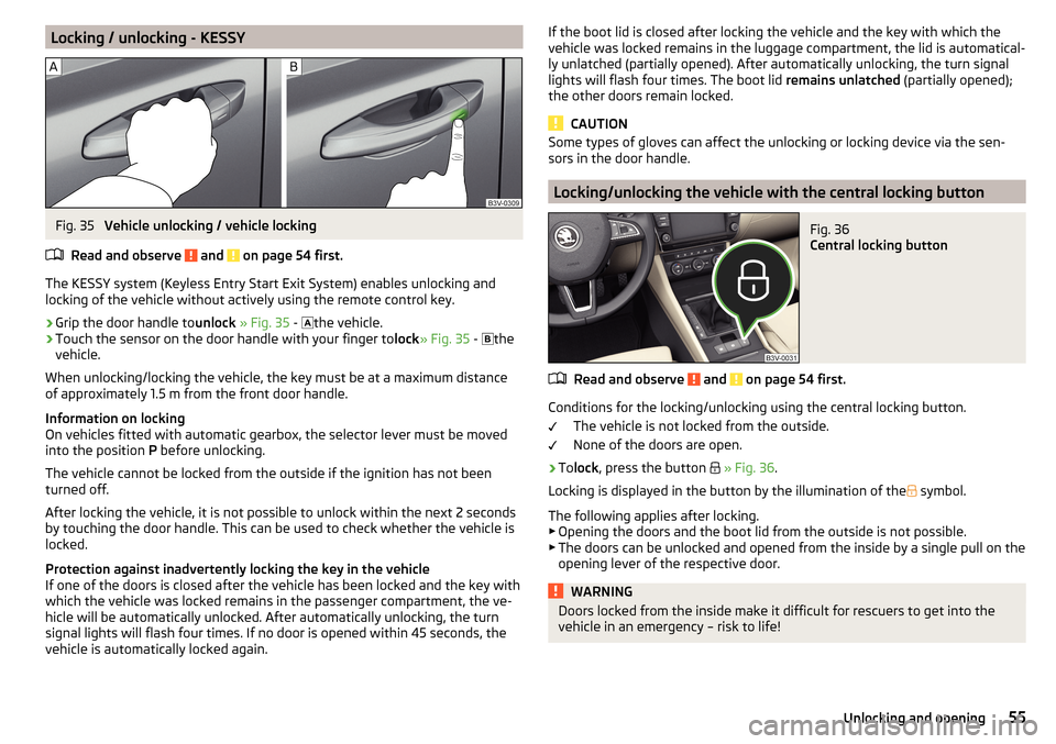
Vehicle unlocking / vehicle locking
Read and observe
and on page 54 first.
The KESSY system (Keyless Entry Start Exit System) enables unlocking and
locking of the vehicle without actively using the remote control key.
›
Grip the door handle to unlock » Fig. 35 -
the vehicle.
›
Touch the sensor on the door handle with your finger to
lock» Fig. 35 -
the
vehicle.
When unlocking/locking the vehicle, the key must be at a maximum distance
of approximately 1.5 m from the front door handle.
Information on locking
On vehicles fitted with automatic gearbox, the selector lever must be moved
into the position P before unlocking.
The vehicle cannot be locked from the outside if the ignition has not been
turned off.
After locking the vehicle, it is not possible to unlock within the next 2 seconds
by touching the door handle. This can be used to check whether the vehicle is
locked.
Protection against inadvertently locking the key in the vehicle
If one of the doors is closed after the vehicle has been locked and the key with
which the vehicle was locked remains in the passenger compartment, the ve-
hicle will be automatically unlocked. After automatically unlocking, the turn
signal lights will flash four times. If no door is opened within 45 seconds, the
vehicle is automatically locked again.
If the boot lid is closed after locking the vehicle and the key with which the
vehicle was locked remains in the luggage compartment, the lid is automatical-
ly unlatched (partially opened). After automatically unlocking, the turn signal
lights will flash four times. The boot lid remains unlatched (partially opened);
the other doors remain locked.
CAUTION
Some types of gloves can affect the unlocking or locking device via the sen-
sors in the door handle.
Locking/unlocking the vehicle with the central locking button
Fig. 36
Central locking button
Read and observe and on page 54 first.
Conditions for the locking/unlocking using the central locking button.
The vehicle is not locked from the outside.
None of the doors are open.
›
To lock , press the button
» Fig. 36 .
Locking is displayed in the button by the illumination of the
symbol.
The following applies after locking. ▶ Opening the doors and the boot lid from the outside is not possible.
▶ The doors can be unlocked and opened from the inside by a single pull on the
opening lever of the respective door.
WARNINGDoors locked from the inside make it difficult for rescuers to get into the
vehicle in an emergency – risk to life!55Unlocking and opening
Page 58 of 336
SafeLockRead and observe
and on page 54 first.
SafeLock prevents the doors from behind opened from inside as well as win-
dow operation. This makes it more difficult for anyone to break into the vehi-
cle.
Switching on
SafeLock switches on when the vehicle is locked.
This function is pointed out by the following message on the display of the in-
strument cluster after the ignition is switched off.
Observe SAFE interlock! Log book!CHECK SAFELOCK
Switch-on display
With the activated SafeLock, the warning light in the driver´s door flashes for 2
seconds in rapid succession, this then starts to flash at longer intervals.
Switching off ▶ By locking twice within 2 seconds.
▶ or: by deactivating the interior monitor and the towing protection
» page 58 .
The warning light in the driver´s door flashes fast for about 2 seconds, goes
out and starts to flash at longer intervals after about 30 seconds.
If the vehicle is locked and the safe securing system is switched off, the door
can be opened separately from the inside by a single pull on opening lever.
The safelock switches on the next time the vehicle is locked.
WARNINGIf the car is locked and the safe securing system activated, no people must
remain in the car as it will then not be possible to either unlock a door or
open a window from the inside. The locked doors make it more difficult for
rescuers to get into the vehicle in an emergency – risk to life!
Individual settings
Read and observe
and on page 54 first.
The following functions of the central locking can be individually adjusted in
infotainment in the
→
→
Opening and closing
menu.
All doors
The function allows you to unlock all doors, the boot lid and the fuel filler flap.
Single door
The function allows you to unlock only the driver's door and the fuel filler flap
with the radio remote control. KESSY allows the unlocking of a single door
which is in the vicinity of the key, as well as the fuel filler flap. The other doors
and the boot lid are only unlocked once the door handle is unlocked or
touched.
Doors on a vehicle side
This function enables you to unlock both doors on the driver's side and the
fuel filler flap with the radio remote control unit. KESSY allows the unlocking of
both doors which are in the vicinity of the key, as well as the fuel filler flap. The
other doors and the boot lid are only unlocked once the door handle is un-
locked or touched.
Automatic locking/unlocking
This function enables the locking of all doors and the boot lid from a speed of
15 km/h. Opening the doors and the boot lid from the outside is not possible.
The renewed unlocking of the doors and the boot lid is carried out when the
ignition key is removed or when the door is opened from inside (depending on
the individual setting for the central locking system).
Note
The individual adjustment of the central locking system is stored (depending
on the Infotainment type) in the active user account personalisation
» page 49 .56Using the system
Page 59 of 336
Open / close doorFig. 37
Door handle/door opening lever
Read and observe
and on page 54 first.
›
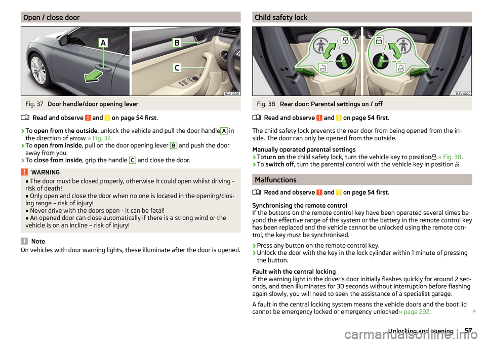
To open from the outside , unlock the vehicle and pull the door handle
A
in
the direction of arrow » Fig. 37.
›
To open from inside , pull on the door opening lever
B
and push the door
away from you.
›
To close from inside , grip the handle
C
and close the door.
WARNING■
The door must be closed properly, otherwise it could open whilst driving -
risk of death!■
Only open and close the door when no one is located in the opening/clos-
ing range – risk of injury!
■
Never drive with the doors open - it can be fatal!
■
An opened door can close automatically if there is a strong wind or the
vehicle is on an incline – risk of injury!
Note
On vehicles with door warning lights, these illuminate after the door is opened.Child safety lockFig. 38
Rear door: Parental settings on / off
Read and observe
and on page 54 first.
The child safety lock prevents the rear door from being opened from the in-
side. The door can only be opened from the outside.
Manually operated parental settings
›
To turn on the child safety lock, turn the vehicle key to position
» Fig. 38 .
›
To switch off , turn the parental control with the vehicle key in position
.
Malfunctions
Read and observe
and on page 54 first.
Synchronising the remote control
If the buttons on the remote control key have been operated several times be-
yond the effective range of the system or the battery in the remote control key
has been replaced and the vehicle cannot be unlocked using the remote con-
trol, the key must be synchronised.
›
Press any button on the remote control key.
›
Unlock the door with the key in the lock cylinder within 1 minute of pressing the button.
Fault with the central locking
If the warning light in the driver's door initially flashes quickly for around 2 sec-
onds, and then illuminates for 30 seconds without interruption before flashing
again slowly, you will need to seek the assistance of a specialist garage.
A fault in the central locking system means the vehicle doors and the boot lid
cannot be emergency locked or emergency unlocked » page 292.
57Unlocking and opening
Page 61 of 336
CAUTIONThe opened glasses storage compartment reduces the effectiveness of the in-
terior monitor. To ensure the full functionality of the interior monitor, the
glasses storage compartment must always be closed before locking the vehi-
cle.
Manually operated tailgate
Introduction
This chapter contains information on the following subjects:
Open/close boot lid
59
Setting the delayed locking of the boot lid
59WARNING■ Never drive with the boot lid open or ajar, as otherwise exhaust gases
may get into the interior of the vehicle – risk of poisoning!■
Ensure that the lock is properly engaged after closing the lid. Otherwise,
the lid might open suddenly while the vehicle is moving, even if the lid was
locked – risk of accident!
■
Make sure that when closing the boot lid, no body parts are crushed -
there is danger of injury!
■
Do not press on the rear window when closing the boot lid, it could crack
– risk of injury!
Open/close boot lid
Fig. 40
Opening / closing tailgate
Read and observe on page 59 first.›
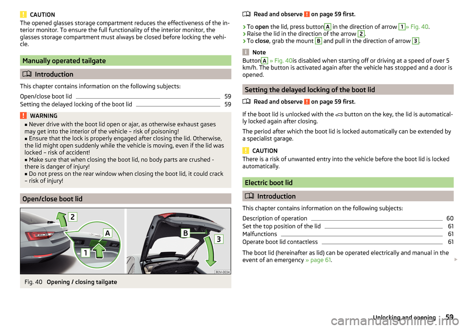
To open the lid, press button
A
in the direction of arrow
1
» Fig. 40 .
›
Raise the lid in the direction of the arrow
2
.
›
To close , grab the mount
B
and pull in the direction of arrow
3
.
Note
ButtonA » Fig. 40 is disabled when starting off or driving at a speed of over 5
km/h. The button is activated again after the vehicle has stopped and a door is
opened.
Setting the delayed locking of the boot lid
Read and observe
on page 59 first.
If the boot lid is unlocked with the button on the key, the lid is automatical-
ly locked again after closing.
The period after which the boot lid is locked automatically can be extended by
a specialist garage.
CAUTION
There is a risk of unwanted entry into the vehicle before the boot lid is locked
automatically.
Electric boot lid
Introduction
This chapter contains information on the following subjects:
Description of operation
60
Set the top position of the lid
61
Malfunctions
61
Operate boot lid contactless
61
The boot lid (hereinafter as lid) can be operated electrically and manual in the
event of an emergency » page 61.
59Unlocking and opening
Page 71 of 336
CAUTIONPoorer visibility is evaluated by a sensor mounted below the windscreen in the
holder of the rear-view mirror. Do not cover the sensor - the system can be af-
fected.
Note
The setting (activate/deactivate) of the automatic driving light control during
rain is stored (depending on the Infotainment type) in the active user account
personalisation » page 49.
Xenon headlight
Read and observe
on page 66 first.
The Xenon headlights (hereinafter referred to as just system) use the drivingdata to automatically ensure the for the best possible light cone in front of the
vehicle.
The system will automatically operate in the following modes: urban, extra-ur-
ban, motorway, rain, fog, adjusting the lighting direction of the headlights for
road illumination on bends.
The system works as long as the light switch is in position
.
WARNINGIf there is a system malfunction the headlights are automatically lowered
to the emergency position, which prevents a possible dazzling of oncoming
traffic. This reduces the cone of light in front of the vehicle. Seek help from
a specialist garage.Fog lights/rear fog lightFig. 51
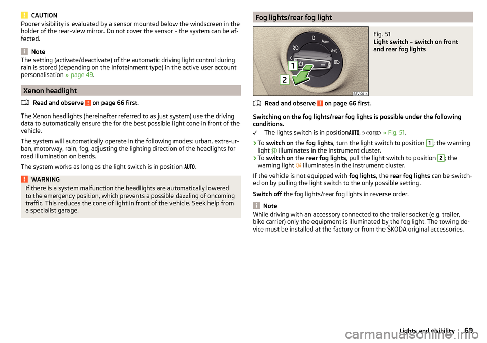
Light switch – switch on front
and rear fog lights
Read and observe on page 66 first.
Switching on the fog lights/rear fog lights is possible under the following
conditions.
The lights switch is in position ,
or
» Fig. 51 .
›
To switch on the fog lights , turn the light switch to position
1
; the warning
light illuminates in the instrument cluster.
›
To
switch on the rear fog lights , pull the light switch to position
2
; the
warning light illuminates in the instrument cluster.
If the vehicle is not equipped with fog lights, the rear fog lights can be switch-
ed on by pulling the light switch to the only possible setting.
Switch off the fog lights/rear fog lights in reverse order.
Note
While driving with an accessory connected to the trailer socket (e.g. trailer,
bike carrier) only the equipment is illuminated by the fog light. The towing de-
vice must be installed at the factory or from the ŠKODA original accessories.69Lights and visibility
Page 109 of 336

Storage compartments under the floor coveringFig. 133
Variant 1: Lift flooring / storage compartments
Fig. 134
Variant 2: Lift flooring / storage compartments
Read and observe
and on page 101 first.
For vehicles that are not equipped with an emergency spare wheel located un- der the flooring of the luggage compartment
B
» Fig. 133 or » Fig. 134 .
Every storage compartment
B
is designed for storing small objects of up to 15
kg. in weight in total.
Using the storage compartments - variant 1
›
Lift the flooring via loop
A
in the direction of arrow » Fig. 133 and completely
fold back or fasten using the loop on the hook on the luggage compartment
cover.
›
Stow the cargo in the storage compartments.
›
Fold back the flooring against the direction of the arrow or remove it from
the hook.
When transporting tall objects in the compartments, the flooring must be fol- ded forward.
Using the storage compartments - variant 2›
Dividing the luggage compartment with variable loading floor » page 111.
›
Lift the floor covering in the direction of arrow » Fig. 134 and hook into hook
C
on the upper edge of the variable loading floor.
›
Stow the cargo in the storage compartments.
›
Unhook hook
C
and fold back the flooring against the direction of the arrow
(fold back the variable loading floor to the initial position if necessary).
When transporting tall objects in the compartments, the hook
C
must be
hooked onto the upper edge of the variable loading floor.
CAUTION
■ Before closing the boot lid check that the flooring is not attached to the
hook with the loop A » Fig. 133 - there is a risk of damaging the hook.■
Before closing the boot lid, check that the cargo transported in the storage
compartments does not strike against the luggage compartment cover - there
is a risk of damage to the lid.
107Transport of cargo
Page 123 of 336
Infotainment
Introductory information
Important information
Introduction to the subject
WARNING■Only use Infotainment in such a way that you have control of the vehicle
in every traffic situation (e.g. Do not write text messages while driving, do
not couple or connect the telephone, do not work with the contact list, do
not enter any destinations, do not connect WLAN or SmartLink etc.)- Other-
wise there is a risk of an accident!■
Always route the connection cable of the external device in such a way
that it does not restrict you when driving.
WARNING■ Adjust the volume to ensure that acoustic signals from outside the vehi-
cle, e.g. sirens from emergency vehicles, can be heard at all times.■
High volumes can cause hearing damage!
CAUTION
In some countries, some Infotainment features can no longer be selected
when the vehicle is running faster than a certain speed. This is not a malfunc-
tion, but complies with the national legal regulations.
Mobile telephones and applications
Fig. 157
QR code with reference to web
pages for checking the compati-
bility of devices
The availability of some of the functions described in this Owner's Manual
depends on the type of device to be connected and the applications installed
in it.
Mobile telephones
On the ŠKODA pages, check to see if Infotainment is compatible with the se-
lected mobile telephones. This check takes place by reading the QR code
» Fig. 157 or after typing the following address into the web browser.
http://go.skoda.eu/compatibility
Due to the multitude of mobile telephones as well as the ongoing develop-
ment of these devices, ŠKODA AUTO cannot always ensure compatibility with
Infotainment unconditionally. It is always recommended to physically check
the function on the associated vehicle, including the ŠKODA Partners, before-
hand.
Only those versions of the selected telephones will be tested and supported
which originate from the official distribution network. The same also applies to
their firmware and software.
The functions of the mobile telephone to be tested may differ from the same
type of mobile telephone depending on the specification for the respective
country or the specific service.
Mobile telephones with the operating system and in the version available at
the time of these tests will be tested. In this regard, it could be the case that
the functions of a mobile telephone may differ with a different operating sys-
tem version compared to the one used with the tested telephone.
ŠKODA AUTO can accept no responsibility for the continuous changes made by the mobile telephone manufacturers and application vendors.
ŠKODA AUTO does not accept any liability for any damage to Infotainment or
the vehicle due to the use of incorrect or illegal applications or the improper or
unauthorized use of mobile telephones.
Applications
Applications can be installed in external devices (e.g. Mobile, tablet) making it
possible to display additional information in the Infotainment screen or to op-
erate Infotainment.
Due to the variety of applications as well as their ongoing development, the
available applications may not work in all external devices. ŠKODA AUTO can
accept no liability for their proper function.
Applications, their use and the required data connection may be chargeable. 121Introductory information
Page 131 of 336
▶You are recommended to speak louder at higher speeds, so that the sound of
your voice is not drowned out by the increased ambient noise.
▶ During voice control, limit additional noise in the vehicle, e.g. passengers
talking at the same time.WARNINGThe emergency number must be dialled manually. Your voice commands
may not be recognized in such situations. The telephone connection may
not be established or the connection may take too much time to complete.
CAUTION
■ The messages are generated by Infotainment. The flawless clarity (e.g. road
or city name) cannot always be guaranteed.■
For some Infotainment languages, there is no voice control available. Info-
tainment indicates this fact through a text message that is displayed after set-
ting the device language screen.
Note
During voice control, no nav. announcements and traffic announcements are
played.
Voice control on / off
Fig. 171
Voice control: Main menu
Activating
›
Press the button on Infotainment
or the button
on the multifunction
steering wheel.
The main menu is displayed » Fig. 171.
Switching off
›
Press the button twice on Infotainment
or press the button twice
on
the multifunction steering wheel.
› Or
Issue the voice command “ End voice control”.
Operation principle
Fig. 172
Example of screen display
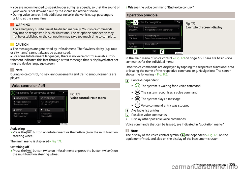
In the main menu of voice control » Fig. 171 on page 129 There are basic voice
commands for the individual menu.
Other voice commands are displayed by tapping the respective functional area
or issuing the name of the respective command (e.g. Navigation). The screen
shows the following » Fig. 172.
Context-dependent:
▶ The system is waiting for a voice command
▶ The system recognises a voice command
▶ The system plays a message
▶ Voice command entry was stopped
Available list entries
Possible voice commands
Display other possible voice commands
Voice commands that can be issued, are indicated in “quotation marks”.
Note
The display of the voice control symbolsA are dependent » Fig. 172 on the
equipment fitted, and also on the display of the instrument cluster.ABC129Infotainment operation
Page 164 of 336
Applies to Infotainment Amundsen, BoleroThe first device (main telephone)The second device (additional tele-phone)HFP (Incoming / outgoing calls), SMS,
Telephone contacts,Bluetooth ®
player a)HFP
(incoming calls),
Bluetooth ®
player a)a)
Only an external device can be connected to Infotainment as a Bluetooth
®
player.
Applies to Infotainment Swing
The first device (main telephone)The second device (additional tele- phone)HFP (Incoming / outgoing calls),
Telephone contacts,Bluetooth ®
player a)Bluetooth ®
player a)
a)
Only an external device can be connected to Infotainment as a Bluetooth
®
player.
Telephone
Applies to Infotainment Columbus, Amundsen, Bolero.
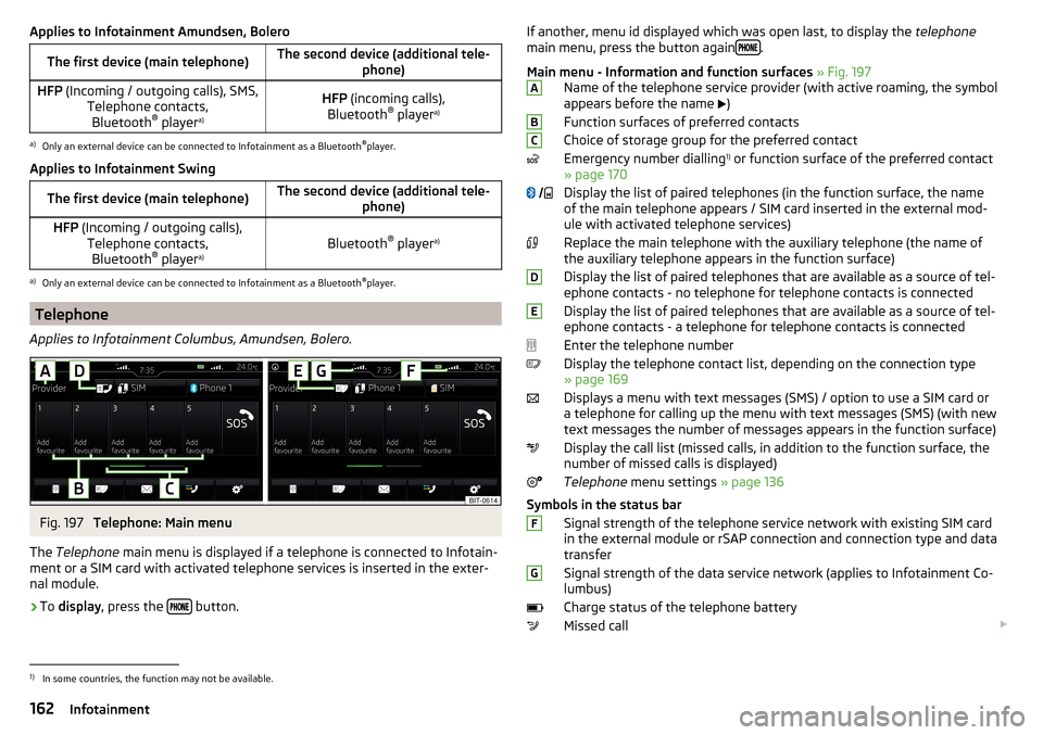
Fig. 197
Telephone: Main menu
The Telephone main menu is displayed if a telephone is connected to Infotain-
ment or a SIM card with activated telephone services is inserted in the exter-
nal module.
›
To display , press the button.
If another, menu id displayed which was open last, to display the
telephone
main menu, press the button again .
Main menu - Information and function surfaces » Fig. 197
Name of the telephone service provider (with active roaming, the symbol
appears before the name
)
Function surfaces of preferred contacts
Choice of storage group for the preferred contact
Emergency number dialling 1)
or function surface of the preferred contact
» page 170
Display the list of paired telephones (in the function surface, the name
of the main telephone appears / SIM card inserted in the external mod-
ule with activated telephone services)
Replace the main telephone with the auxiliary telephone (the name of
the auxiliary telephone appears in the function surface)
Display the list of paired telephones that are available as a source of tel-
ephone contacts - no telephone for telephone contacts is connected
Display the list of paired telephones that are available as a source of tel-
ephone contacts - a telephone for telephone contacts is connected
Enter the telephone number
Display the telephone contact list, depending on the connection type
» page 169
Displays a menu with text messages (SMS) / option to use a SIM card or a telephone for calling up the menu with text messages (SMS) (with new
text messages the number of messages appears in the function surface)
Display the call list (missed calls, in addition to the function surface, the
number of missed calls is displayed)
Telephone menu settings » page 136
Symbols in the status bar Signal strength of the telephone service network with existing SIM card
in the external module or rSAP connection and connection type and data
transfer
Signal strength of the data service network (applies to Infotainment Co-
lumbus)
Charge status of the telephone battery
Missed call ABC
DEFG1)
In some countries, the function may not be available.
162Infotainment
Page 165 of 336
Current call
Incoming SMS
Ongoing data transfer
The PIN code of the SIM card inserted in the external module has not
been entered
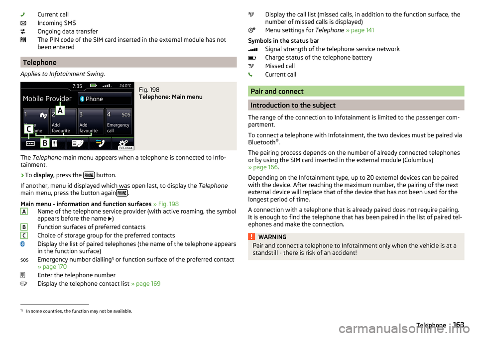
Telephone
Applies to Infotainment Swing.
Fig. 198
Telephone: Main menu
The Telephone main menu appears when a telephone is connected to Info-
tainment.
›
To display , press the button.
If another, menu id displayed which was open last, to display the Telephone
main menu, press the button again
.
Main menu - information and function surfaces » Fig. 198
Name of the telephone service provider (with active roaming, the symbol
appears before the name )
Function surfaces of preferred contacts
Choice of storage group for the preferred contacts
Display the list of paired telephones (the name of the telephone appears
in the function surface)
Emergency number dialling 1)
or function surface of the preferred contact
» page 170
Enter the telephone number
Display the telephone contact list » page 169
ABCDisplay the call list (missed calls, in addition to the function surface, the
number of missed calls is displayed)
Menu settings for Telephone » page 141
Symbols in the status bar Signal strength of the telephone service network
Charge status of the telephone battery
Missed call
Current call
Pair and connect
Introduction to the subject
The range of the connection to Infotainment is limited to the passenger com-
partment.
To connect a telephone with Infotainment, the two devices must be paired via
Bluetooth ®
.
The pairing process depends on the number of already connected telephones
or by using the SIM card inserted in the external module (Columbus)
» page 166 .
Depending on the Infotainment type, up to 20 external devices can be paired
with the device. After reaching the maximum number, the pairing of the next
external device will replace that of the device that has not been used for the
longest period of time.
A connection with a telephone that is already paired does not require pairing.
It is enough to find the telephone that has been paired in the list of paired tel-
ephones and make the connection.
WARNINGPair and connect a telephone to Infotainment only when the vehicle is at a
standstill - there is risk of an accident!1)
In some countries, the function may not be available.
163Telephone