stop start SKODA SUPERB 2016 3.G / (B8/3V) Owner's Guide
[x] Cancel search | Manufacturer: SKODA, Model Year: 2016, Model line: SUPERB, Model: SKODA SUPERB 2016 3.G / (B8/3V)Pages: 336, PDF Size: 53.89 MB
Page 210 of 336
The selector lever is not locked when quickly moving across the position N
(e.g. from R to D/S ). This, for example, helps to rock out a vehicle that is stuck,
e.g. in a bank of snow. The selector lever lock will engage if the lever is in posi-
tion N for more than approx. 2 seconds without the brake pedal being de-
pressed.
If it is not possible to release the gear selector from mode P in the usual man-
ner, then this can be emergency unlocked » page 293.
Note
If you want to switch the selector lever from mode P to mode D/S or vice ver-
sa, move the selector lever quickly. This prevents that you accidentally select
mode R or N.
Manual shifting of gears (Tiptronic)
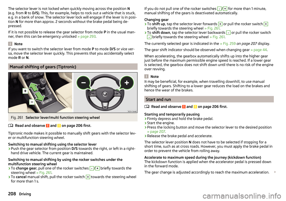
Fig. 261
Selector lever/multi function steering wheel
Read and observe
and on page 206 first.
Tiptronic mode makes it possible to manually shift gears with the selector lev-
er or multifunction steering wheel.
Switching to manual shifting using the selector lever
›
Push the gear selector from position D/S towards the right, or left in a right-
hand drive vehicle. The current gear is maintained.
Switching to manual shifting by using the rocker switches under the
multifunction steering wheel
›
To change gear , pull one of the rocker switches
-
/
+
briefly towards the
steering wheel » Fig. 261.
›
To cancel manual shift, pull the rocker switch
+
towards the steering wheel
for more than 1 s.
If you do not pull one of the rocker switches -/+ for more than 1 minute,
manual shifting of the gears is deactivated automatically.
Changing gear›
To shift up , tap the selector lever forwards
+
or pull the rocker switch
+
briefly towards the steering wheel » Fig. 261.
›
To shift down , tap the selector lever backwards
-
or pull the rocker switch
-
briefly towards the steering wheel » Fig. 261.
The currently selected gear is indicated in the » Fig. 259 on page 207 display.
The gear shift indicator should be observed when changing gear » page 44.
When accelerating, the gearbox automatically shifts up into the higher gear
just before the maximum permissible engine speed is reached. If a lower gear
is selected, the gearbox does not shift down until there is no risk of the engine
over revving.
Note
It may be beneficial, for example, when travelling downhill, to use manual
shifting of gears. Shifting to a lower gear reduces the load on the brakes and
hence the wear of the brakes.
Start and run
Read and observe
and on page 206 first.
Starting and temporarily pausing
›
Firmly depress and hold the brake pedal.
›
Start the engine.
›
Press the locking button and move the selector lever to the desired position
» page 207 .
›
Release the brake pedal and accelerate.
The selector lever position N does not have to be selected if stopping for a
short time, such as at cross roads. However, you must apply the brake pedal in
order to prevent the vehicle from rolling away.
Accelerate to maximum speed during the journey (kickdown function)
The kickdown function is applied when the accelerator pedal is pressed down
in the forward mode.
The gear change is adjusted accordingly to reach the maximum acceleration.
208Driving
Page 211 of 336
When approaching maximum speed (launch control function)1)
The launch control function is available in mode S or Tiptronic.›
Disable the TCS » page 212, Braking and stabilisation systems .
›
START STOP deactivate » page 202, Manually disable / enable system .
›
Fully depress and hold the brake pedal with your left foot.
›
Fully depress the accelerator pedal with your right foot.
›
Release the brake pedal - the vehicle is running at maximum acceleration.
Driving in neutral (“coasting”)
When releasing the accelerator pedal, the vehicle moves without the braking
effect of the engine.
Operating conditions
▶ The selector lever is in the D/S position.
▶ Driving mode Eco or Individual (Drive - Eco) is selected » page 240, Select the
driving mode (Driving Mode Selection) .
▶ The vehicle is travelling at more than 20 km/h.
▶ No trailer or other accessory is connected to the trailer socket.
The gear is selected again automatically, when you depress the accelerator or
brake pedal or pull the left rocker switch
-
towards the steering wheel
» page 208 , Manual shifting of gears (Tiptronic) .
WARNINGRapid acceleration, particularly on slippery roads, can lead to loss of control
of the vehicle – risk of accident!
Running in the engine and economical driving
Introduction
This chapter contains information on the following subjects:
Running in the engine
209
Tips for economical driving
209
DriveGreen function
210
Radiator shutters
210Running in the engine
During the first 1,500 km, the driving manner determines the quality of the
running in process on a new engine.
During the first 1,000 km , the engine should not be charged with more than
3/4 of the maximum permitted engine revs and without the trailer.
In the area of 1,000 to 1,500 kilometres , the engine load can be increased up
to the maximum permitted engine speed.
Tips for economical driving
The fuel consumption depends on the driving style, road condition, weather
conditions and the like.
For an economical driving style, the following instructions must be observed. ▶ Avoid unnecessary acceleration and braking.
▶ Observe the recommended gear » page 44.
▶ Avoid full throttle and high speeds.
▶ Reduce idling.
▶ Avoid short distances.
▶ Ensure the correct tyre inflation pressure is maintained » page 277.
▶ Avoid unnecessary ballast.
▶ Remove the roof rack when it is not needed.
▶ Only switch on electrical consumers (e.g. seat heating) for as long as they are
needed. In the Infotainment menu
→
→
conv. Consumers,
, up to three
consumers who currently have the largest share of fuel consumption, can be
displayed.
▶ Before switching on, ventilate the cooling system briefly and do not use the
cooling system with open windows.
▶ Do not leave windows open at high speed.
1)
This function is only valid for some engines.
209Starting-off and Driving
Page 213 of 336
Avoiding damage to your vehicle
Introduction
This chapter contains information on the following subjects:
Driving Tips
211
Driving through water
211
Driving Tips
Only drive on such roads and in such terrain that match the vehicle parameters
» page 303 , Technical data as well as your driving skills.
The driver is always responsible for deciding whether the vehicle can handle
travelling in the given terrain.
WARNING■ Adjust the speed and driving style to the current visibility, weather, road
and traffic conditions. Too high a speed or an erroneous manoeuvre may
cause serious injury and damage to the vehicle.■
Combustible objects such as dry leaves or twigs caught under the base of
the vehicle could ignite on hot vehicle parts - risk of fire!
CAUTION
■ Pay attention to the ground clearance of the vehicle! When driving over ob-
jects which are larger than the ground clearance, the vehicle can get damaged.■
Any objects that get trapped under the vehicle floor must be removed as
soon as possible. These items can cause damage to the vehicle (e.g. on parts
of the fuel system or the brake system).
Driving through water
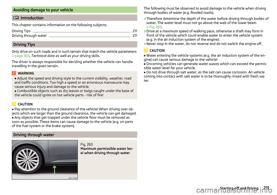
Fig. 263
Maximum permissible water lev-
el when driving through water
The following must be observed to avoid damage to the vehicle when driving
through bodies of water (e.g. flooded roads).›
Therefore determine the depth of the water before driving through bodies of
water. The water level must not go above the web of the lower beam
» Fig. 263 .
›
Drive at a maximum speed of walking pace, otherwise a shaft may form in
front of the vehicle which could enable water to enter the vehicle system
(e.g. in the air induction system of the engine).
›
Never stop in the water, do not reverse and do not switch the engine off.
CAUTION
■ Water entering the vehicle systems (e.g. the air induction system of the en-
gine) can cause serious damage to the vehicle!■
Oncoming vehicles can generate water waves which can exceed the permis-
sible water level for your vehicle.
■
Do not drive through salt water, as the salt can cause corrosion. An vehicle
coming into contact with salt water is to be thoroughly rinsed with fresh wa-
ter.
211Starting-off and Driving
Page 218 of 336
Settings in InfotainmentRead and observe
and on page 215 first.
›
Press the button, then tap on the function surface
→
Parking and ma-noeuvring
.
■ ParkPilot - Settings for the parking aid
■
Activate automatically
- Activate/deactivate the compact parking aid display
(when driving forward)
■
Front volume
- Adjust the volume of the beeps for obstacle detection in front
■
Front tone setting
- Setting the pitch of the beeps for obstacle detection in
front
■
Rear volume
- Set the volume level of the beeps for the rear obstacle detec-
tion
■
Rear tone setting
- Setting the pitch of the beeps for the rear obstacle detec-
tion
■
Entertainment fading
/
Entert. Fading
- Lowers the audio volume (e.g. radio vol-
ume) with activated parking aid
■
Manoeuvre braking
- Activation / deactivation of the automatic emergency
braking
Operation
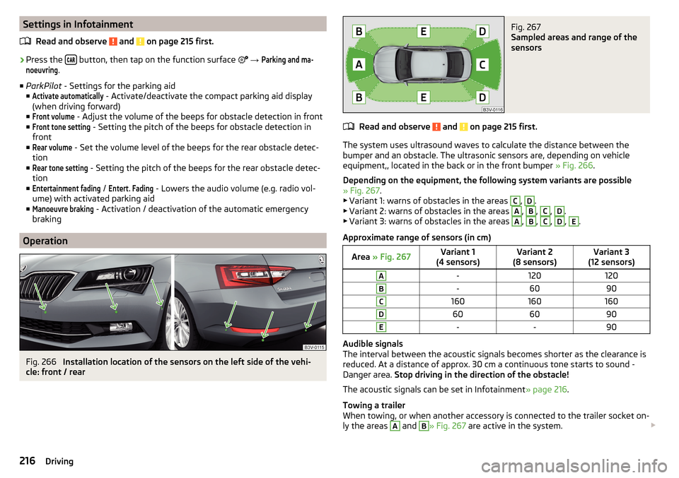
Fig. 266
Installation location of the sensors on the left side of the vehi-
cle: front / rear
Fig. 267
Sampled areas and range of the
sensors
Read and observe and on page 215 first.
The system uses ultrasound waves to calculate the distance between the
bumper and an obstacle. The ultrasonic sensors are, depending on vehicle
equipment,, located in the back or in the front bumper » Fig. 266.
Depending on the equipment, the following system variants are possible
» Fig. 267 .
▶ Variant 1: warns of obstacles in the areas
C
,
D
.
▶ Variant 2: warns of obstacles in the areas
A
,
B
,
C
,
D
.
▶ Variant 3: warns of obstacles in the areas
A
,
B
,
C
,
D
,
E
.
Approximate range of sensors (in cm)
Area » Fig. 267Variant 1
(4 sensors)Variant 2
(8 sensors)Variant 3
(12 sensors)A-120120B-6090C160160160D606090E--90
Audible signals
The interval between the acoustic signals becomes shorter as the clearance is
reduced. At a distance of approx. 30 cm a continuous tone starts to sound -
Danger area. Stop driving in the direction of the obstacle!
The acoustic signals can be set in Infotainment » page 216.
Towing a trailer
When towing, or when another accessory is connected to the trailer socket on-
ly the areas
A
and
B
» Fig. 267 are active in the system.
216Driving
Page 223 of 336
NoteThe brightness of the indicator light is dependent on the setting of the ve-
hicle lighting. With the low or high beam on the brightness of the light will be
lower.
Activation / deactivation
Read and observe
and on page 219 first.
The activation or deactivation of the system can be carried out in one of the
following ways. ▶ In the instrument cluster display » page 48, Menu item
Assist systems
.
▶ In Infotainment in the menu
→
→
Driver assistance
(Applies to the wizard
for “Blind Spot” Monitoring).
▶ In Infotainment in the
menu
→
→
Parking and manoeuvring
(Applies to
Rear Traffic Alerts).
After switching off and switching on the ignition, depending on the setting pri-
or to switching off the ignition, the systems remains activated / deactivated.
Note
When activating the wizard for “blind spot” monitoring, the warning lights
illuminate briefly in the two exterior mirrors.
Malfunctions
Read and observe
and on page 219 first.
If the systems are not available for some unknown reason, an appropriate
message appears in the display of the instrument cluster.
Sensor covered / dirty
If the sensor is dirty or covered, a message indicating that there is no sensor
view appears. Clean or remove the obstructing object from the sensor environ-
ment » Fig. 271 on page 218 .
Systems unavailable
If the systems are currently unavailable, a message regarding the unavailability
appears. Stop the vehicle, switch off the engine and then start it again. If the
systems are still not available, seek the assistance of a specialist garage.
System fault
In the case of a system fault, an error message appears. Seek help from a spe-
cialist garage.
Reversing camera
Introduction
This chapter contains information on the following subjects:
Operation
222
Activation / deactivation
222
Function surfaces
223
Orientation lines and roadway
223
Mode - Lateral Parking
224
Mode - Parallel parking
224
mode- Driving up to a trailer / Distance monitoring
225
Mode - Monitoring the area behind the vehicle
225
The rear view camera (following as system) helps the driver when parking and
manoeuvring by displaying the area behind the vehicle in the Infotainment
screen (hereinafter only referred to as screen).
There are four modes available for different situations during the park and ma- noeuvring action. The mode change is carried out using the function surfaces
on the screen » page 223.
WARNING■
The general information relating to the use of assistance systems must
be observed » page 212, in section Introduction .■
The system detects obstacles. The display of the auxiliary boxes and lines
is independent of the actual vehicle environment. The driver must judge for
themselves whether the vehicle can park safely in the selected parking
space.
■
The camera may not be soiled or obscured, otherwise the system function
will be significantly affected - there is a risk of accident. For information on
cleaning » page 261 .
221Assist systems
Page 227 of 336
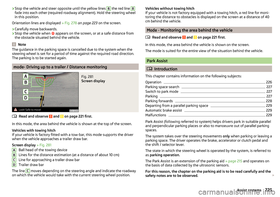
›Stop the vehicle and steer opposite until the yellow lines 6 the red line 8fade into each other (required roadway alignment). Hold the steering wheel
in this position.
Orientation lines are displayed » Fig. 278 on page 223 on the screen.›
Carefully move backwards.
›
Stop the vehicle when
appears on the screen, or at a safe distance from
the obstacle situated behind the vehicle.
Note
The guidance in the parking space is cancelled due to the system when the
steering wheel is set for a period of time against the required road direction.
The parking is to be started again.
mode- Driving up to a trailer / Distance monitoring
Fig. 281
Screen display
Read and observe and on page 221 first.
In this mode, the area behind the vehicle is shown at the top of the screen.
Vehicles with towing hitch
If your vehicle is factory fitted with a tow-bar, this mode supports the driver
when the vehicle approaches a trailer draw bar.
Screen display » Fig. 281
Ball head of the towing device
Lines for the distance estimation (at a distance of about 10 cm)
Line for approaching a trailer draw bar
Trailer draw bar
The line
C
moves depending on the steering angle and indicate the roadway
on which the vehicle would take with the current steering wheel position.
ABCDVehicles without towing hitch
If your vehicle is not factory equipped with a towing hitch, a red line for moni-
toring the distance to obstacles is displayed on the screen at a distance of 40
cm behind the vehicle.
Mode - Monitoring the area behind the vehicle
Read and observe
and on page 221 first.
In this mode, the area behind the vehicle is shown on the screen.
The mode is suited for the entire view of the situation behind the vehicle.
Park Assist
Introduction
This chapter contains information on the following subjects:
Operation
226
Parking space search
227
Switch to park mode
227
Parking
227
Parking forwards
228
Departing from a parallel parking space
229
Automatic brake assist
229
Malfunctions
229
Park Assist (following referred to system) helps drivers park in suitable parallel
and perpendicular parking places or also to manoeuvre out of parallel parking
spaces.
The system takes over the steering movements only when parking or leaving a
parking space. The driver operates the brake, accelerator or clutch pedal and
the shift / selector lever.
The state in which the steering wheel is operated by the system, is referred to
as parking operation.
The Park Assist is an extension of the parking aid » page 215 and operates on
the basis of data collected by the ultrasonic sensors.
For this reason, the chapter on the parking aid is to be read carefully and the safety notes are to be observed.
225Assist systems
Page 228 of 336
WARNING■The general information relating to the use of assistance systems must
be observed » page 212, in section Introduction .■
During the parking process, the system automatically performs rapid
steering movements. While it is doing so, do not place your hands between
the steering wheel – risk of injury!
■
During a parking manoeuvre on loose or slippery surfaces (gravel, snow,
ice, etc.) you may stray from the calculated road. It is therefore recommen-
ded that you do not use the system in such situations.
CAUTION
The correct evaluation of the parking space and the parking procedure de-
pends on the circumference of the wheels on the vehicle.■
The system only works correctly if the vehicle is fitted with the wheel size
approved by ŠKODA AUTO.
■
Abstain from using the system when the vehicle is fitted with snow chains or
a temporary spare wheel.
■
If wheels other than those approved by ŠKODA AUTO are fitted, the resulting
position of the vehicle in the parking space can differ slightly. This can be avoi-
ded by readjusting the system at a specialist garage.
CAUTION
If other vehicles are parked behind or on the curb, the system can drive your
vehicle over the kerb or up to the kerb - there is a risk of damage to the
wheels. If necessary, intervene in good time.
Note
■ We recommend performing the parking at a safe speed to about 5 km/h.■The parking procedure can be stopped at any time by pressing the
» Fig. 282 on page 226 button or by a steering intervention.OperationFig. 282
System button
Read and observe and on page 226 first.
The system support is provided in the following manner.
▶ While the parking space search is going on, a measurement and evaluation of
the parking space size is completed.
▶ The display of the instrument cluster (hereinafter only display) shows suita-
ble parking spaces and a parking mode is recommended.
▶ The display shows instructions and information before the start and during
the parking.
▶ Based on the calculated road surface, the front wheels will be automatically
rotated during the parking.
Conditions for the system function
The system can look for a parking space only if the following basic conditions
are met.
The system is activated.
The vehicle is travelling at less than 40 km/h.
The vehicle is travelling at less than 20 km/h.
The distance to a number of parked vehicles is approximately 0.5 - 1.5 m.
TCS is activated » page 214.
The system can only carry out the parking procedure if the following basic con-
ditions are met.
The vehicle is travelling at less than 7 km/h.
The parking procedure takes less than 6 minutes.
There is no driver intervention in the automatic steering operation.
TCS is activated » page 214.
The TCS does not engage.
No trailer or other accessory is connected to the trailer socket.
226Driving
Page 230 of 336
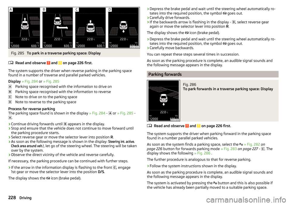
Fig. 285
To park in a traverse parking space: Display
Read and observe
and on page 226 first.
The system supports the driver when reverse parking in the parking space
found in a number of traverse and parallel parked vehicles.
Display » Fig. 284 or » Fig. 285
Parking space recognised with the information to drive on
Parking space recognised with the information to reverse
Note to drive on to the parking space
Note to reverse to the parking space
Process for reverse parking
The parking space found is shown in the display » Fig. 284 -
or
» Fig. 285 -
.
›
Continue driving forwards until
appears in the display.
›
Stop and ensure that the vehicle does not continue to move forward until
the parking procedure starts.
›
Select reverse gear or move the selector lever into position R.
›
As soon as the following message is shown in the display:
Steering int. active.Check area around veh.!
, let go of the steering wheel. The steering will be taken
over by the system.
›
Observe the direct vicinity of the vehicle and reverse carefully.
If necessary, the parking procedure can be continued with further steps.
›
If the arrow in the information display is flashing to the front , engage
1st gear or move the selector lever into the position D/S.
The display shows the icon (brake pedal).
›Depress the brake pedal and wait until the steering wheel automatically ro-
tates into the required position, the symbol goes out.›
Carefully drive forwards.
›
If the backwards arrow is flashing in the display -
, select reverse gear
again or move the selector lever into position R.
The display shows the
icon (brake pedal).
›
Depress the brake pedal and wait until the steering wheel automatically ro-
tates into the required position, the symbol
goes out.
›
Carefully move backwards.
You can repeat these steps several times in succession.
As soon as the parking procedure is complete, an audible signal sounds and the following message appears in the display.
Parking forwards
Fig. 286
To park forwards in a traverse parking space: Display
Read and observe and on page 226 first.
The system supports the driver when parking forward in the parking space
found in a number parallel parked vehicles.
As soon as the system finds a parking space, select the
» Fig. 282 on
page 226 button for forwards parking mode » Fig. 283 on page 227 -
. The
display shows the following » Fig. 286 .
The further procedure is analogous to that for reverse parking.
›
Follow the system instructions shown in the display.
As soon as the parking procedure is complete, an audible signal sounds and
the following message appears in the display.
The system is activated by pressing the button and this is also possible if
the vehicle has already been partially moved to a suitable parking space.
228Driving
Page 235 of 336
Adaptive Cruise Control (ACC)
Introduction
This chapter contains information on the following subjects:
Settings in Infotainment
233
Operation
234
Automatic stopping and starting
234
Operation overview
235
Start control
235
Stop/resume control
235
Set/change the desired speed
236
Set the clearance level
236
Special driving situations
236
Overtaking and towing
237
Malfunctions
237
The Adaptive Cruise Control (hereinafter referred to as ACC) maintains the set
speed or the distance to the vehicle ahead without the accelerator or brake
pedal being pressed.
The front of the vehicle and the distance to the vehicle ahead is monitored by
a radar sensor » page 212.
The state in which the ACC maintains the speed or the proximity is described
as control from here on.
WARNING■
The general information relating to the use of assistance systems must
be observed » page 212, in section Introduction .■
The driver must always be ready to take over the operation of the accel-
erator and brake pedal.
■
The ACC does not react when approaching a stationary obstacle, such as
traffic jams, vehicle breakdowns or vehicles waiting at a traffic light.
■
The ACC does not respond to crossing or oncoming objects.
■
If the ACC does not decelerate fast enough, immediately apply the vehi-
cle's foot brake.
WARNINGFor safety reasons, do not use the ACC under the following conditions.■When driving in turning lanes, motorway exits or construction sites, to
avoid an unwanted acceleration to the stored speed.■
When visibility is poor, (e.g. fog, heavy rain, thick snowfall).
■
When road conditions are poor (e.g. ice, slippery road, gravel, dirt road).
■
Driving in “sharp” corners or in steep gradients / on steep inclines.
■
When driving through places where metal objects (such as metal build-
ings, railway tracks, etc.) can be found.
■
When driving through very divided and enclosed spaces (such as large-ca-
pacity garages, car ferries, tunnels and the like.).
Note
■ The ACC is designed primarily for use on motorways.■The ACC reduces the speed by automatically releasing the accelerator or by
means of a braking procedure as appropriate. If the brakes are used for an au-
tomatic speed reduction at any moments, then the brake light illuminates.■
In case of failure of more than one brake light on the vehicle or on the con-
nected trailer, the ACC becomes unavailable.
■
The control automatically cancels the engagement of the brake supportive
assistance systems (e.g. ESC) or when the maximum permitted engine speed is
exceeded.
Settings in Infotainment
Read and observe
on page 233 first.
›
Press the button, then tap on the function surface
→
Driver assistance
.
■ ACC (adaptive cruise control) - Setting for the adaptive cruise control
■
Driving progr.:
- Set the vehicle acceleration when adaptive cruise control is
activated 1)
■
Last selec. Distance
- Switch on/off of the last distance selected
■
Distance:
- Set the distance monitoring to the vehicles ahead
1)
This can be set in the menu on vehicles with a travel mode option as follows » page 240 .
233Assist systems
Page 236 of 336
OperationFig. 294
Instrument cluster display: Examples of ACC displays
Fig. 295
Instrument cluster display: Examples of ACC status displays
Read and observe
on page 233 first.
The ACC allows you to set a speed of 30 - 160 or 210 km / h (depending on
equipment) and the distance to the vehicle ahead in the range of a very short
to a very long distance.
The ACC adjusts the set speed with respect to the detected vehicle ahead,
thus maintaining the selected proximity.
The ACC can detect a vehicle that is up to approx. 150 m ahead using the radar
sensor.
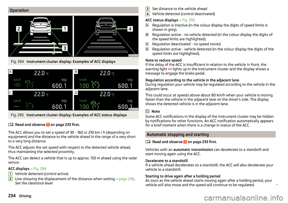
ACC displays » Fig. 294
Vehicle detected (control active)
Line showing the displacement of the distance when setting » page 236,
Set the clearance level
12Set distance to the vehicle ahead
Vehicle detected (control deactivated)
ACC status displays » Fig. 295
Regulation is inactive (in the colour display the digits of speed limits is
shown in grey).
Regulation active - no vehicle detected (in the colour display the digits of
the speed limits are highlighted).
Regulation deactivated - no speed stored.
Regulation active - vehicle detected (in the colour display the digits of the
speed limits are highlighted).
Note to reduce speed
If the delay of the ACC is insufficient in relation to the vehicle in front, the
warning light lights up in the instrument cluster and the display shows a
message to engage the brake pedal.
Regulation according to the vehicle in the adjacent lane
During regulation your vehicle may be regulated according to the vehicle in the
adjacent lane.
This could occur at speeds above about 80 km/h when your vehicle is moving
faster than the vehicle in the adjacent lane on the driver's side. The display
shows the detected vehicle is in the adjacent lane.
Note
Some ACC notifications in the display of the instrument cluster may be hidden
by notifications for other functions. An ACC notification automatically appears
for a brief moment when there is a change in status of the ACC.
Automatic stopping and starting
Read and observe
on page 233 first.
Vehicles with an automatic transmission can decelerate to a standstill and
start moving again using the ACC.
Decelerate to a standstill
If a vehicle ahead decelerates to a standstill, the ACC will also decelerate your
vehicle to a standstill.
Starting to drive again after a holding period
As soon as the vehicle ahead starts moving again after a holding period, your
vehicle will also move and the speed will continue to be regulated.
34234Driving