stop start SKODA SUPERB 2016 3.G / (B8/3V) Service Manual
[x] Cancel search | Manufacturer: SKODA, Model Year: 2016, Model line: SUPERB, Model: SKODA SUPERB 2016 3.G / (B8/3V)Pages: 336, PDF Size: 53.89 MB
Page 237 of 336
If the preceding vehicle starts moving again after a long break, then to contin-
ue the regulation press the accelerator pedal or lever to set the lever in
» page 235 position.
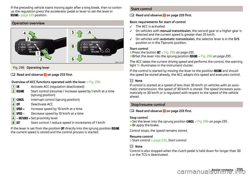
Operation overview
Fig. 296
Operating lever
Read and observe
on page 233 first.
Overview of ACC functions operated with the lever » Fig. 2961Activate ACC (regulation deactivated)2Start control (resume) / increase speed by 1 km/h at a time
(sprung position)3Interrupt control (sprung position)4Deactivate ACC5 Increase speed by 10 km/h at a time6 Decrease speed by 10 km/h at a timeA Set proximity levelBStart control / reduce speed in increments of 1 km/h
If the lever is set from the position
directly into the sprung position
the current speed is stored and the control process is started.
Start control
Read and observe
on page 233 first.
Basic requirements for start of control The ACC is activated.
On vehicles with manual transmission , the second gear or a higher gear is
selected and the current speed is greater than 25 km/h.
On vehicles with automatic transmission , the selector lever is in the D/S
position or in the Tiptronic position.
Start control
›
Press the button
» Fig. 296 on page 235 .
›
OrSet the lever into the sprung position
» Fig. 296 on page 235 .
The ACC takes the current driving speed and performs the control, the warning light illuminates in the instrument cluster.
If the control is started by moving the lever to the position and should
the speed be stored already, the ACC adopts this speed and executes control.
Note
If control is started at a speed of less than 30 km/h on vehicles with an auto-
matic transmission, the speed of 30 km/h is stored. The speed increases auto-
matically to 30 km/h or is regulated with respect to the speed of the vehicle
ahead.
Stop/resume control
Read and observe
on page 233 first.
Stop control
›
Set the lever into the sprung position
» Fig. 296 on page 235 .
›
Or apply the brake.
Control stops, the speed remains stored.
Resume control
›
Start control » page 235, Start control .
Note
Control is also stopped when the clutch pedal is held down for longer than 30
s or the TCS is deactivated.235Assist systems
Page 238 of 336
Set/change the desired speedRead and observe
on page 233 first.
The desired speed can be set or changed using the control lever » Fig. 296 on
page 235 .
Setting/changing the speed by increments of 10 km/h at a time (
) - re-
quirements
The ACC is activated.
Increasing/reducing the speed by increments of 1 km/h at a time (
/
-
requirements
The ACC is activated.
Vehicle control takes place.
Changing the speed by adopting the current speed ( ) - requirements
The ACC is activated.
The vehicle is moving at a speed other than that which is stored.
Note
■
If during control the speed is increased by pressing the accelerator, control is
temporarily stopped. Upon releasing the accelerator, control is automatically
resumed.■
If during control the speed is reduced by applying the brake, control is stop-
ped. Control needs to be restarted in order to resume » page 235.
■
If the vehicle is controlled by a lower speed than the stored speed, then
the current speed is stored by pressing the button again
and the speed is
reduced in increments of 1 km/h.
Set the clearance level
Read and observe
on page 233 first.
The proximity to the vehicle ahead can be set with the lever » Fig. 296 on
page 235 or in Infotainment » page 233, Settings in Infotainment .
Setting by means of the lever
›
Set the switch Adjust in the spring-tensioned position
or
» Fig. 296
on page 235 .
The display of the instrument cluster shows line
2
» Fig. 294 on page 234 ,
which indicates the proximity.
› Using the switch
on the lever, adjust the line 2 to the desired dis-
tance.
Note
■ If the proximity is changed in infotainment, the change will only come into
effect after a subsequent activation of the ACC.■
The higher the speed, the greater the proximity to the vehicle ahead.
■
The adjustment of the distance is stored (depending on the Infotainment
type) in the active user account personalisation » page 49.
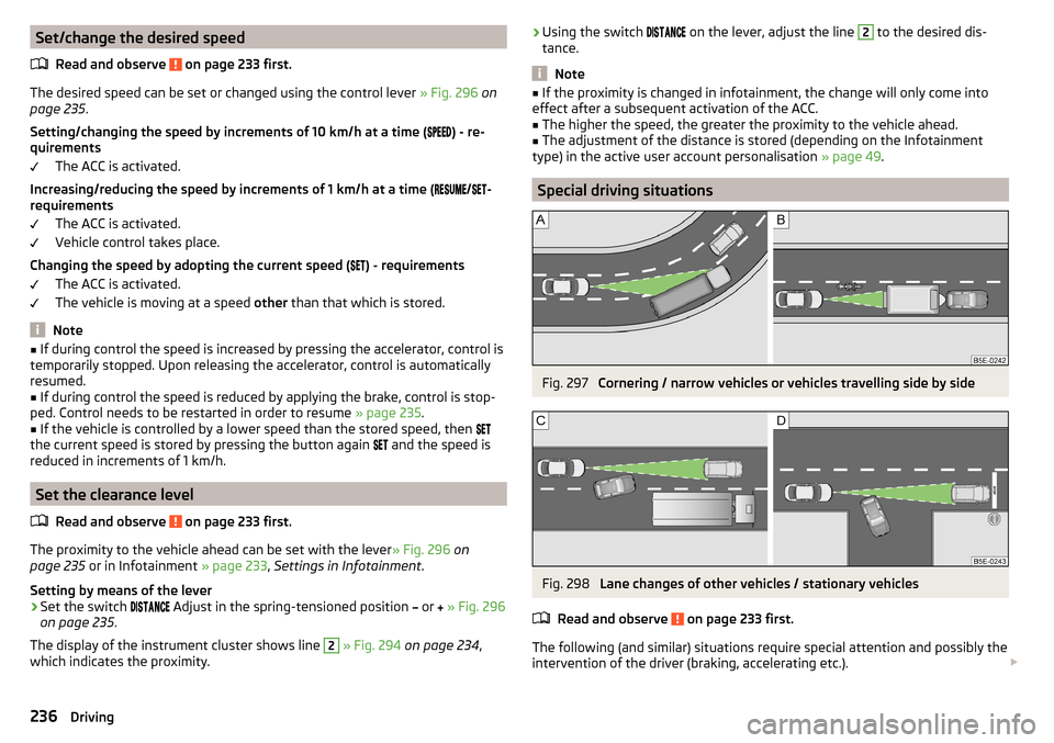
Special driving situations
Fig. 297
Cornering / narrow vehicles or vehicles travelling side by side
Fig. 298
Lane changes of other vehicles / stationary vehicles
Read and observe
on page 233 first.
The following (and similar) situations require special attention and possibly the intervention of the driver (braking, accelerating etc.).
236Driving
Page 239 of 336
When cornering
When driving into or driving out of long corners, it could be that a vehicle is
travelling in the adjacent lane and is scanned by the radar » Fig. 297 -
. The
host vehicle is then controlled according to this vehicle.
Narrow vehicles or vehicles travelling side by side
A narrow or offset vehicle driving can only be recognized by the ACC if this is
located in the scanning range of the radar » Fig. 297 -
.
Other vehicles changing lanes
Vehicles that change onto the lane with a small distance » Fig. 298 -
may not
be detected by ACC in good time.
Stationary vehicles
The ACC does not detect stationary objects! When a vehicle detected by the
ACC turns or sheers off and there is a stationary vehicle in front of this vehi-
cle, » Fig. 298 -
the ACC does not respond to the stationary vehicle.
Vehicles with special load or special body parts
Other vehicles with a load or with body parts protruding from the sides, back
or top of the vehicle contour may not be detected by the ACC.
Overtaking and towing
Read and observe
on page 233 first.
When overtaking
When your vehicle is being controlled at a speed that is lower than the set
speed and the turn signal is operated, ACC assesses this situation as meaning
that the driver wishes to overtake. The ACC automatically accelerates the vehi-
cle, thereby reducing the proximity to a vehicle ahead.
If your vehicle changes to the overtaking lane and no vehicle is detected
ahead, ACC accelerates until the set speed is reached and then keeps it con-
stant.
Acceleration can be cancelled at any time by touch on the brake pedal or
pressing the button on the lever
» Fig. 296 on page 235 .
Towing a trailer
When towing, or if another accessory is connected to the trailer socket, ACC
control is set with a lower rate. The manner of driving should therefore be
adapted to this limitation.
Malfunctions
Read and observe
on page 233 first.
If, for some unknown reason, ACC is not available, the warning light
appears
in the display of the instrument cluster and an appropriate message is shown.
Sensor covered / dirty
If the sensor cover or the sensor is dirty or covered, a message appears on the
instrument cluster display stating there is no sensor view. Clean the sensor
cover or remove the obstacles » Fig. 264 on page 212 .
If there is no sensor view in the winter, the snow on the sensor under the cov- er could be the reason. The ACC is functional again after the snow melts away
from the sensor.
ACC not available
If the ACC is currently unavailable, a message concerning the unavailability ap-
pears. Stop the vehicle, switch off the engine and then start it again. If ACC
continues to be unavailable, seek the assistance of a specialist garage.
ACC fault
With an ACC fault, an error message appears. Seek help from a specialist ga-
rage.
Front Assist
Introduction
This chapter contains information on the following subjects:
Settings in Infotainment
238
Operation
238
Distance warning
238
Warning and automatic braking
238
Deactivation/activation
239
Malfunctions
240
The Front Assist (hereinafter referred to as the system) warns you of the dan-
ger of a collision with a vehicle or another obstacle in front of the vehicle, and
tries to avoid a collision or mitigate its consequences by automatically applying
the brakes where necessary.
The area in front of the vehicle is monitored by a radar sensor » page 212.
237Assist systems
Page 242 of 336
WARNINGIn the following situations, Front Assist should be switched off for safety
reasons.■
When the vehicle is being towed away.
■
When the vehicle is on a rolling test bench.
■
If an unfounded warning or a system action was taken.
■
When on a truck, or a car ferry service or similar.
Malfunctions
Read and observe
and on page 238 first.
If, for some unknown reason, the system is not available, an appropriate mes-
sage appears in the display of the instrument cluster.
Sensor covered / dirty
If the sensor cover or the sensor is dirty or covered, a message appears on the
instrument cluster display stating there is no sensor view. Clean the sensor
cover or remove the obstacles » Fig. 264 on page 212 .
If there is no sensor view in the winter, the snow on the sensor under the cov- er could be the reason. The system is functional again after the snow melts
away from the sensor.
System unavailable
If the system is currently unavailable, a message concerning the unavailability
appears. Stop the vehicle, switch off the engine and then start it again. If the
system still is not available, seek the assistance of a specialist garage.
Select the driving mode (Driving Mode Selection)
Introduction
This chapter contains information on the following subjects:
Adaptive Chassis Control (DCC)
240
mode
Eco240
Mode
Comfort241
Mode
Normal241
Mode
Sports241
Mode
individual241Mode selection and Infotainment display241Settings for individual
mode242
By selecting the driving mode, the driving behaviour can be adapted to the de-
sired mode of operation.
the following modes
Eco
.
Comfort
.
normal
.
Sports
and
individual
are available.
The mode
Comfort
is only available on vehicles with adaptive chassis control
(DCC).
WARNINGPlease take note of the general points relating to the use of assistance
systems » page 212, in section Introduction .
Adaptive Chassis Control (DCC)
Read and observe
on page 240 first.
The adaptive chassis control (following known as DCC) provides the ability to
adjust the shock characteristics for the sporty, normal or comfortable driving
when the corresponding control mode is selected.
The DCC evaluates steering response and road conditions while driving contin- uously and adjusts the suspension behaviour within the selected driving mode
accordingly.
mode
Eco
Read and observe on page 240 first.
This mode is suitable for a relaxed style of driving and helps to save fuel.
Selecting this mode primarily affects the function of the following systems.
Drive
Vehicle acceleration is more relaxed than in
Normal
mode.
The recommended gear is controlled such to achieve the lowest possible fuel
consumption » page 44.
If the START-STOP system is deactivated manually » page 202, this will be au-
tomatically activated.
The automatic gearbox is set automatically to mode E » page 207 .
240Driving
Page 250 of 336
Data from the sensor is supplemented by information from the Infotainment
Navigation. This is the reason why traffic signs with maximum speeds can also
be shown on sections of roads which do not have any traffic signs.
Warning when exceeding the speed limit
The warning when exceeding the permissible speed (based on the detected
traffic sign) can be activated and set in Infotainment » page 247.
Mode when towing a trailer
For vehicles with a factory-fitted towing device, in the Infotainment it is possi- ble to enable or disable the relevant traffic signs for trailer operation and the
top speed for towing a trailer » page 247, Settings in Infotainment .
Additional display
Read and observe
on page 246 first.
If the menu item Road sign is currently not shown » Fig. 307 on page 247 -
,
the road sign with the speed limit will appear in the upper display area of the
instrument cluster » Fig. 307 on page 247 -
,
.
If several traffic signs are detected simultaneously, in some cases the next
traffic sign will also be displayed in the colour display - » Fig. 307 on page 247 -
.
All detected traffic signs can be displayed via the multifunction display in the
menu item Traffic Sign Recognition » Fig. 307 on page 247 -
.
This additional function can be activated/deactivated in Infotainment
» page 247 .
Note
The setting (activation/deactivation) of the auxiliary display will be saved (de-
pending on the Infotainment type) in the active user account personalisation
» page 49 .
Malfunction and information messages
Read and observe
on page 246 first.
If, for some unknown reason, the system is not available, an appropriate mes-
sage appears in the display of the instrument cluster.
Sensor covered / dirty
If the screen in the sensor area is dirty, iced or misted, a caution to clean the
screen appears. Clean the windscreen or remove the obstacles from the sen-
sor area.
System fault
In the case of a system fault, an error message appears. Seek help from a spe-
cialist garage.
System limitation (Navigation data not available)
If the Infotainment Navigation submits no data, a message regarding the limi- tation of the system function appears. Check whether the map documents are
up to date or whether the vehicle is currently in a location for which no naviga-
tion data are available.
Traffic signs unavailable
No speed restriction is detected, a message is displayed regarding the unavail-
ability of road signs.
Fatigue detection
The fatigue detection system (following known as system) recommends the
driver taking a break from driving when, because of the driver's steering be-
haviour, driver fatigue can be detected.
From the starting of the journey, the system evaluates the steering behaviour
at speeds 65-200 km/h. If, while driving, there have been changes in the steer-
ing behaviours that are evaluated by the system as indicating possible fatigue,
a break recommendation is issued.
Conditions under which a break from driving is detected by the system ▶ The vehicle is stopped and the ignition switched off.
▶ The vehicle is stopped, the seat belt removed and the driver's door opened.
▶ The vehicle is stopped for more than 15 minutes.
If none of these conditions are met or if the driving style is not changed, the
system recommends a driving break again after 15 minutes.
The system can be activated//deactivated in infotainment in the
→
→
Driver assistance
menu.
Pause recommendation
The icon appears and the following message for a few seconds in the display
of the instrument cluster and a message about the detected fatigue. An au-
dible signal is also emitted.
248Driving
Page 270 of 336
We recommend when refilling using refill bottles that you use refill bottles
from ŠKODA Original Accessories.
When adding AdBlue ®
take note of the minimum and maximum AdBlue ®
tank
capacity shown in the display of the instrument cluster » page 40.
Refill AdBlue ®
under the following conditions.
The vehicle is on a horizontal surface.
The ignition is switched off.
Refilling›
Press the fuel filler flap in direction of arrow
1
and fold in the direction of
arrow
2
» Fig. 317 .
›
Unscrew the tank cap in the direction of arrow
3
.
›
Remove the tank cap and place in the recess on top of the fuel filler flap in
the direction of arrow
4
.
›
Refill AdBlue ®
in the neck
A
by means of a refill or a fuel nozzle refill (follow
the instructions on the container or the instructions of the petrol station op-
erator).
The AdBlue ®
- tank is full when no AdBlue ®
flows from the refill bottle or as
soon as the correctly operated pump cuts out for the first time. Do not contin-
ue refilling AdBlue ®
.
›
After refilling AdBlue ®
put the cap on the fuel filler neck and turn in the oppo-
site direction of the arrow
3
until it engages.
›
Close the fuel filler flap until it clicks into place.
Before continuing your journey , switch on just the ignition for 30 s so that the
refilling can be recognized by the system. Only then start the engine.
Engine compartment
Introduction
This chapter contains information on the following subjects:
Open the bonnet and close
269
Engine compartment overview
269
Windscreen washer fluid
270WARNINGNever cover the engine with additional insulation material (e.g. with a cov-
er) – risk of fire!WARNINGWhen working in the engine compartment, the following instructions must
be observed - risk of injury or fire. The engine compartment of your car is a
hazardous area!WARNINGInstructions before beginning work in the engine compartment■Stop the engine and remove the ignition key, on vehicles with the KESSY
system, open the driver's door.■
Switch on the parking brake.
■
For vehicles with manual transmission the lever into the neutral position.
On vehicles with automatic transmission , place the selector lever in the P
position.
■
Allow the engine to cool.
■
Never open the bonnet if you can see steam or coolant flowing out of the
engine compartment – risk of scalding! Wait until the steam or coolant has
stopped escaping.
WARNINGInformation for working in the engine room■Keep everyone away from the engine compartment.■
Do not touch any hot engine parts – risk of burns!
■
Never touch the radiator fan. The radiator fan suddenly switch on approx.
10 minutes after switching off the ignition!
■
Do not smoke or use open flames in the vicinity of the engine.
■
Do not leave any items (e.g. cloths or tools) in the engine compartment.
This presents a fire hazard and the risk of engine damage.
■
Read and observe the information and warning instructions on the fluid
containers.
WARNINGInformation for working in the engine compartment with the engine run-
ning■
If it is necessary to work on the engine compartment with the engine run-
ning, then observe the rotating engine parts and electrical plants - it can
be fatal!
■
Never touch the electric wiring on the ignition system.
■
Avoid short circuits in the electrical system, particularly on the vehicle's
battery.
268General Maintenance
Page 275 of 336
Brake fluidFig. 323
Brake fluid reservoir
Check the brake fluid under the following conditions.The vehicle is on a horizontal surface.
The engine is turned off.
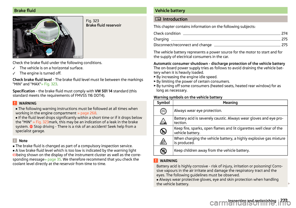
Check brake fluid level - The brake fluid level must lie between the markings
“MIN” and “MAX” » Fig. 323.
Specification - the brake fluid must comply with VW 501 14 standard (this
standard meets the requirements of FMVSS 116 DOT4).
WARNING■ The following warning instructions must be followed at all times when
working in the engine compartment » page 268.■
If the fluid level drops significantly within a short time or if it drops below
the “MIN” » Fig. 323mark, this may be an indication of a leak in the brake
system.
Stop driving - There is a risk of an accident! Seek help from a
specialist garage.
Note
■ The brake fluid is changed as part of a compulsory inspection service.■A low brake fluid level which is too low is indicated by the warning light
being shown on the display of the instrument cluster as well as the corre-
sponding message » page 35. We therefore recommend that you check the
coolant level directly at the reservoir from time to time.Vehicle battery
Introduction
This chapter contains information on the following subjects:
Check condition
274
Charging
275
Disconnect/reconnect and change
275
The vehicle battery represents a power source for the motor to start and for the supply of electrical consumers in the car.
Automatic consumer shutdown - discharge protection of the vehicle battery
The on-board power supply tries as follows to avoid draining the vehicle bat-
tery when it is heavily loaded.
▶ By increasing the engine idle speed.
▶ By limiting the power of certain consumers.
▶ By turning off some consumers (heated seats, heated rear window) for as
long as necessary.
Warning symbols on the vehicle battery
SymbolMeaningAlways wear eye protection.Battery acid is severely caustic. Always wear gloves and eye pro-
tection.Keep fire, sparks, open flames and lit cigarettes well clear of the
vehicle battery.When charging the vehicle battery, a highly explosive gas mixture
is produced.Keep children away from the vehicle battery.WARNINGBattery acid is highly corrosive - risk of injury, irritation or poisoning! Corro-
sive vapours in the air irritate and damage the respiratory tract and the
eyes. The following guidelines must be observed.■
Always wear protective gloves, eye and skin protection when handling
the vehicle battery.
273Inspecting and replenishing
Page 277 of 336
ChargingRead and observe
and on page 273 first.
Only charge the vehicle battery when the ignition and all consumers are
switched off.
Refer to the instructions of the charger manufacturer.
Charging
›
For vehicles with START-STOP system or auxiliary heating, connect the
terminal of the charger on the
pole of the battery, the
terminal of the
charger to the earth point of the engine » page 288.
›
For vehicles without START-STOP system or auxiliary heating, connect the
terminals of the charger to the corresponding battery poles ( at
.
at
).
›
Plug the mains cable of the charger into the power socket and switch on the
device.
›
After charging has been successful: Switch off the charger and remove the
mains cable from the power socket.
›
Disconnect the terminals of the charger from the vehicle battery.
A charging current of 0.1 multiple of the total vehicle battery capacity (or low-
er) must be used until full charging is achieved.
WARNING■ When charging the vehicle battery, hydrogen is released - risk of explo-
sion. An explosion can be caused from sparks or connection or releasing
the cable plug while the ignition is on.■
The so-called “quick charging” of the vehicle battery is dangerous and re-
quires a special charger and specialist knowledge. Therefore, have“Quick
loading” carried out by a specialist garage.
Disconnect/reconnect and change
Read and observe
and on page 273 first.
The new vehicle battery must have the same capacity, voltage, current and the
same size as the original Battery.
We recommend you have the battery replaced by a specialist garage.
›
To disconnect the battery, switch off the ignition and disconnect first the
negative terminal , and only after this the positive
.
›To
connect the battery, first connect the positive terminal , and only after
this the negative terminal .
After disconnecting and re-connecting the vehicle battery, the following func-
tions or devices are partially or completely inoperative.Function / deviceOperating measurePower windows» page 64Panorama sliding/tilting roof» page 65Sun screen» page 66Time setting» page 44
CAUTION
■ Disconnect the vehicle battery only with the ignition turned off - there is a
risk of damaging the electrical system of the vehicle.■
Before disconnecting the battery, close the electric tailgate, all the windows,
the sliding / tilting roof and the electric sunshade - otherwise malfunctions of
equipment elements may occur.
■
Under no circumstances must the connection cables be connected incorrect-
ly – risk of fire.
Note
After disconnecting and re-connecting the vehicle battery, we recommend
having the vehicle checked by a specialist to ensure that the full functionality
of all electrical systems is guaranteed.275Inspecting and replenishing
Page 289 of 336
›For vehicles with
manual transmission , set the lever in the neutral position.›On vehicles with automatic transmission , place the selector lever in the P
position.›
Start the engine.
›
Plug the connector
6
into 12 volt socket » page 96.
›
Switch on the air compressor with the ON and OFF switch
9
.
›
Once a tyre inflation pressure of 2.0-2.5 bar is reached, turn off the air com-
pressor. Maximum run time of 6 minutes » .
›
If you cannot reach an air pressure of 2.0 - 2.5 bar, unscrew the tyre inflation
hose
7
from the tyre valve.
›
Drive the vehicle approx. 10 metres forwards or backwards to allow the seal-
ing agent to “distribute” in the tyre.
›
Firmly screw the tyre inflation hose
7
back onto the tyre valve and repeat
the inflation process.
›
Stick the corresponding sticker
1
on the dashboard in the driver's field of
view.
Once a tyre inflation pressure of 2.0 – 2.5 bar is achieved, continue the journey
at a maximum speed of 80 km/h (50 mph).
WARNING■ If the tire does not inflate at least. 2.0 bar, the damage is too great. The
sealing agent cannot be used to seal the tyre. Stop driving! Seek help
from a specialist garage.■
The tyre inflation hose and air compressor may get hot as the tyre is be-
ing inflated – risk of burning.
CAUTION
Switch off the air compressor after running 6 minutes at the most – risk of
overheating! Allow the air compressor to cool a few minutes before switching
it on again.
Information for driving with repaired tyres
Read and observe
on page 285 first.
The inflation pressure of the repaired tyre must be checked after driving for 10
minutes.
If the tyre inflation pressure is 1.3 bar or less
›
The tyre cannot be properly sealed with the breakdown kit.
Do not drive
the vehicle! Seek help from a specialist garage.
If the tyre inflation pressure is 1.3 bar or more›Set the tyre pressure back to the correct value » page 277.›
Continue driving carefully to the nearest specialist garage at a maximum
speed of 80 km/h (50 mph).
WARNINGA tyre filled with sealant has the same driving characteristics as a standard
tyre. The following guidelines must be observed.■
Do not drive faster than 80 km/h (50 mph).
■
Avoid accelerating at full throttle, sharp braking and fast cornering.
Jump-starting
Introduction
This chapter contains information on the following subjects:
Start using the battery from another vehicle
288WARNING■ The following instructions must be followed at all times when working on
the engine compartment » page 268.■
When handling the vehicle battery, the following warnings must be ob-
served » page 273 .
■
A discharged vehicle battery may already freeze at temperatures just be-
low 0 °C. If the battery is frozen, do not carry out a jump start with the bat-
tery of another vehicle – risk of explosion!
■
Never jump-start vehicle batteries with an acid level that is too low – risk
of explosion and caustic burns!
287Emergency equipment and self-help
Page 290 of 336
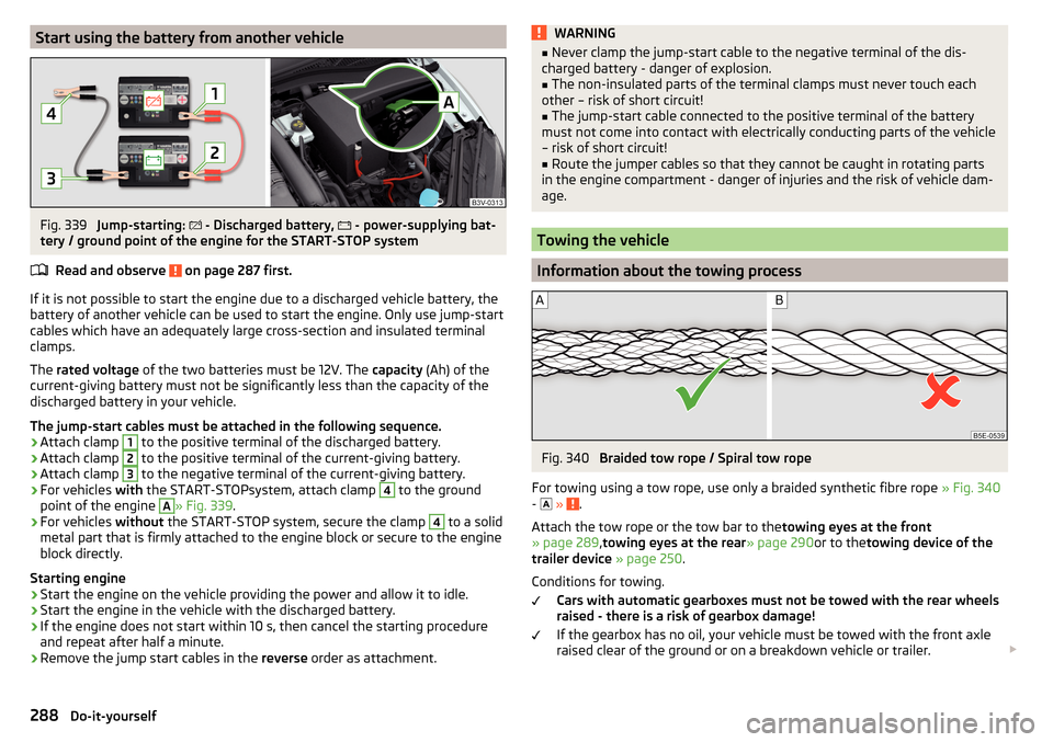
Start using the battery from another vehicleFig. 339
Jump-starting:
- Discharged battery,
- power-supplying bat-
tery / ground point of the engine for the START-STOP system
Read and observe
on page 287 first.
If it is not possible to start the engine due to a discharged vehicle battery, the
battery of another vehicle can be used to start the engine. Only use jump-start
cables which have an adequately large cross-section and insulated terminal
clamps.
The rated voltage of the two batteries must be 12V. The capacity (Ah) of the
current-giving battery must not be significantly less than the capacity of the
discharged battery in your vehicle.
The jump-start cables must be attached in the following sequence.
›
Attach clamp
1
to the positive terminal of the discharged battery.
›
Attach clamp
2
to the positive terminal of the current-giving battery.
›
Attach clamp
3
to the negative terminal of the current-giving battery.
›
For vehicles with the START-STOPsystem, attach clamp
4
to the ground
point of the engine
A
» Fig. 339 .
›
For vehicles without the START-STOP system, secure the clamp
4
to a solid
metal part that is firmly attached to the engine block or secure to the engine
block directly.
Starting engine
›
Start the engine on the vehicle providing the power and allow it to idle.
›
Start the engine in the vehicle with the discharged battery.
›
If the engine does not start within 10 s, then cancel the starting procedure
and repeat after half a minute.
›
Remove the jump start cables in the reverse order as attachment.
WARNING■
Never clamp the jump-start cable to the negative terminal of the dis-
charged battery - danger of explosion.■
The non-insulated parts of the terminal clamps must never touch each
other – risk of short circuit!
■
The jump-start cable connected to the positive terminal of the battery
must not come into contact with electrically conducting parts of the vehicle
– risk of short circuit!
■
Route the jumper cables so that they cannot be caught in rotating parts
in the engine compartment - danger of injuries and the risk of vehicle dam-
age.
Towing the vehicle
Information about the towing process
Fig. 340
Braided tow rope / Spiral tow rope
For towing using a tow rope, use only a braided synthetic fibre rope » Fig. 340
-
»
.
Attach the tow rope or the tow bar to the towing eyes at the front
» page 289 ,towing eyes at the rear » page 290or to thetowing device of the
trailer device » page 250 .
Conditions for towing. Cars with automatic gearboxes must not be towed with the rear wheels
raised - there is a risk of gearbox damage!
If the gearbox has no oil, your vehicle must be towed with the front axle
raised clear of the ground or on a breakdown vehicle or trailer.
288Do-it-yourself