door SKODA SUPERB 2016 3.G / (B8/3V) Workshop Manual
[x] Cancel search | Manufacturer: SKODA, Model Year: 2016, Model line: SUPERB, Model: SKODA SUPERB 2016 3.G / (B8/3V)Pages: 336, PDF Size: 53.89 MB
Page 271 of 336
CAUTIONRefill only operating fluids of the correct specification - danger of damaging
the vehicle!
Note
■ Fluids with the proper specifications can be purchased from the ŠKODA Origi-
nal Accessories or from the ŠKODA Genuine Parts ranges.■
We recommend you have the battery replaced by a specialist garage.
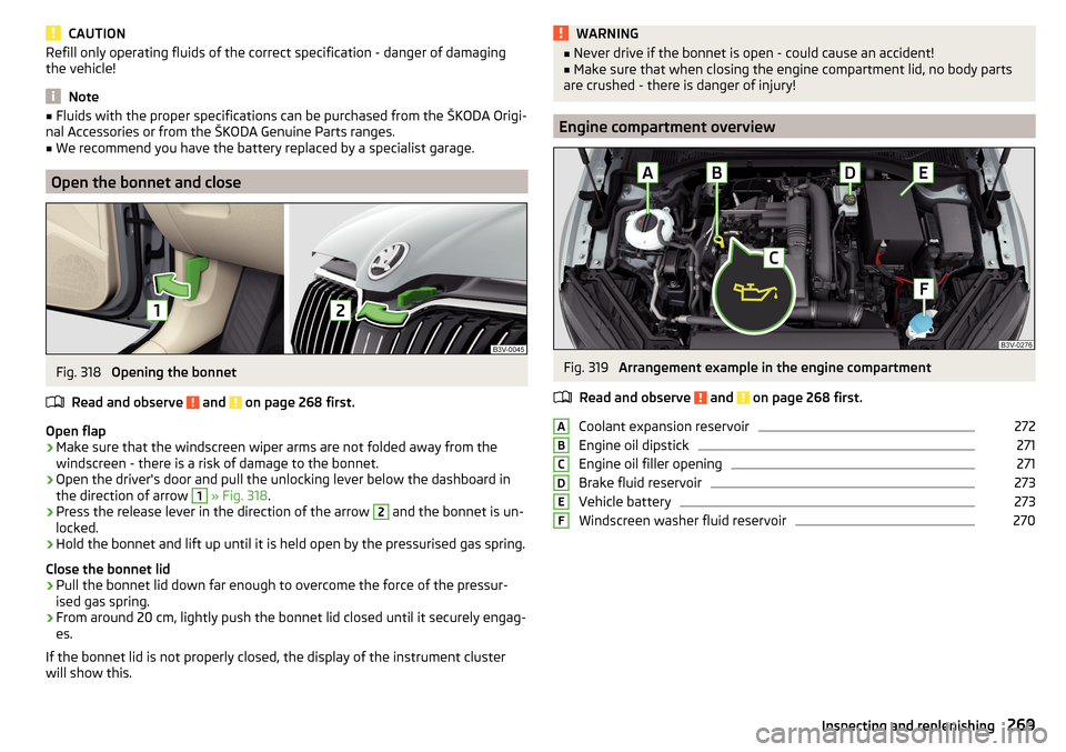
Open the bonnet and close
Fig. 318
Opening the bonnet
Read and observe
and on page 268 first.
Open flap
›
Make sure that the windscreen wiper arms are not folded away from the
windscreen - there is a risk of damage to the bonnet.
›
Open the driver's door and pull the unlocking lever below the dashboard in
the direction of arrow
1
» Fig. 318 .
›
Press the release lever in the direction of the arrow
2
and the bonnet is un-
locked.
›
Hold the bonnet and lift up until it is held open by the pressurised gas spring.
Close the bonnet lid
›
Pull the bonnet lid down far enough to overcome the force of the pressur-
ised gas spring.
›
From around 20 cm, lightly push the bonnet lid closed until it securely engag-
es.
If the bonnet lid is not properly closed, the display of the instrument cluster
will show this.
WARNING■ Never drive if the bonnet is open - could cause an accident!■Make sure that when closing the engine compartment lid, no body parts
are crushed - there is danger of injury!
Engine compartment overview
Fig. 319
Arrangement example in the engine compartment
Read and observe
and on page 268 first.
Coolant expansion reservoir
272
Engine oil dipstick
271
Engine oil filler opening
271
Brake fluid reservoir
273
Vehicle battery
273
Windscreen washer fluid reservoir
270ABCDEF269Inspecting and replenishing
Page 282 of 336

Do-it-yourself
Emergency equipment and self-help
Emergency equipment
Introduction
This chapter contains information on the following subjects:
Placement of the first aid kit and warning triangle
280
Placement of reflective vest
280
Fire extinguisher
281
Vehicle tool kit
281
Placement of the first aid kit and warning triangle
Fig. 327
Placement of first aid kits and warning triangle: Variant 1 / Loos-
en warning triangle
Fig. 328
Placement of the first-aid kit and
the warning triangle: Variant 2
The following information applies for the first aid kit and warning triangle from
the ŠKODA Original Accessories.
Placing the first-aid kit
The first-aid kit can be attached by a strap to the right-hand side of the boot
» Fig. 327 or » Fig. 328 .
Depending on the equipment fitted, in the same place a storage compartment
may be located in which the first aid kit can be stowed.
Placing of the warning triangle - variant 1
The warning triangle can be inserted into the recess under the loading edge
and secured with the fastener tape » Fig. 327.›
To release , press the clasp on the tape in the direction of arrow
1
fold open
the belt
A
in the direction of arrow
2
» Fig. 327 .
›
To secure , fold up the belt
A
against the arrow direction
2
until it locks in-
to place.
Warning triangle – version 2
The warning triangle can be stored in the recess under the loading edge
» Fig. 328 . Before it is taken out, the floor covering of the luggage compart-
ment must be raised.
WARNINGProperly secure the first aid kit and the warning triangle, or there is a risk of
injury in the event of sudden braking or a vehicle collision.
Placement of reflective vest
Fig. 329
Stowage compartment for the
reflective vest in the front door
The reflective vest can be stowed in the storage compartment
A
inside the
storage compartment of the front door » Fig. 329.
280Do-it-yourself
Page 283 of 336
It is possible to store the reflective vests for the passengers on the rear seat in
the storage compartment in the rear doors.
Fire extinguisher
Fig. 330
Release the fire extinguisher
The fire extinguisher is attached by two straps in a bracket under the front
passenger's seat.
›
To remove the fire extinguisher, release the safety catches on the two belts
in the direction of arrow » Fig. 330and remove the fire extinguisher.
›
To secure , place the fire extinguisher back in the mount and secure with the
belts.
The Owner´s Manual is fitted next to the fire extinguisher.
Pay attention to the expiration date of the fire extinguisher. After this date,
the correct function of the device is not guaranteed.
WARNINGAlways properly secure the fire extinguisher, there is a risk of injury in the
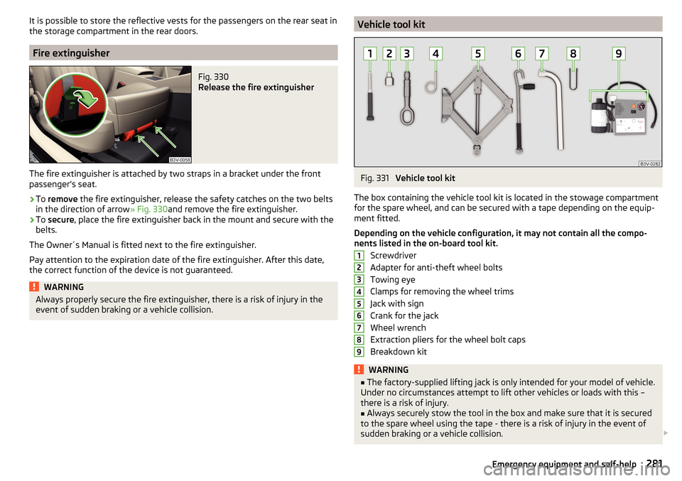
event of sudden braking or a vehicle collision.Vehicle tool kitFig. 331
Vehicle tool kit
The box containing the vehicle tool kit is located in the stowage compartment for the spare wheel, and can be secured with a tape depending on the equip-
ment fitted.
Depending on the vehicle configuration, it may not contain all the compo-
nents listed in the on-board tool kit.
Screwdriver
Adapter for anti-theft wheel bolts
Towing eye
Clamps for removing the wheel trims
Jack with sign
Crank for the jack
Wheel wrench
Extraction pliers for the wheel bolt caps
Breakdown kit
WARNING■ The factory-supplied lifting jack is only intended for your model of vehicle.
Under no circumstances attempt to lift other vehicles or loads with this –
there is a risk of injury.■
Always securely stow the tool in the box and make sure that it is secured
to the spare wheel using the tape - there is a risk of injury in the event of
sudden braking or a vehicle collision.
123456789281Emergency equipment and self-help
Page 287 of 336
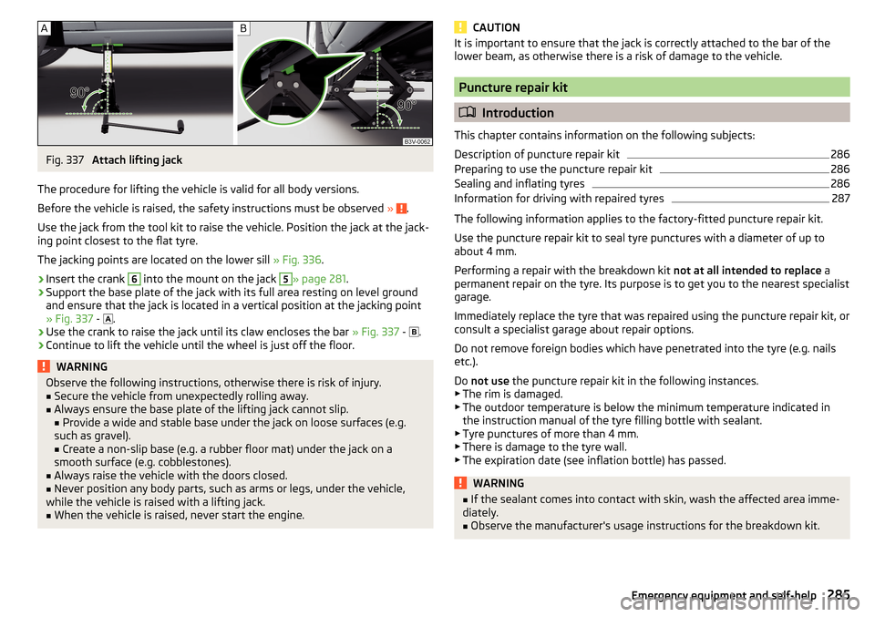
Fig. 337
Attach lifting jack
The procedure for lifting the vehicle is valid for all body versions.
Before the vehicle is raised, the safety instructions must be observed »
.
Use the jack from the tool kit to raise the vehicle. Position the jack at the jack-
ing point closest to the flat tyre.
The jacking points are located on the lower sill » Fig. 336.
›
Insert the crank
6
into the mount on the jack
5
» page 281 .
›
Support the base plate of the jack with its full area resting on level ground
and ensure that the jack is located in a vertical position at the jacking point
» Fig. 337 -
.
›
Use the crank to raise the jack until its claw encloses the bar
» Fig. 337 -
.
›
Continue to lift the vehicle until the wheel is just off the floor.
WARNINGObserve the following instructions, otherwise there is risk of injury.■Secure the vehicle from unexpectedly rolling away.■
Always ensure the base plate of the lifting jack cannot slip.
■ Provide a wide and stable base under the jack on loose surfaces (e.g.
such as gravel). ■ Create a non-slip base (e.g. a rubber floor mat) under the jack on a
smooth surface (e.g. cobblestones).
■
Always raise the vehicle with the doors closed.
■
Never position any body parts, such as arms or legs, under the vehicle,
while the vehicle is raised with a lifting jack.
■
When the vehicle is raised, never start the engine.
CAUTIONIt is important to ensure that the jack is correctly attached to the bar of the
lower beam, as otherwise there is a risk of damage to the vehicle.
Puncture repair kit
Introduction
This chapter contains information on the following subjects:
Description of puncture repair kit
286
Preparing to use the puncture repair kit
286
Sealing and inflating tyres
286
Information for driving with repaired tyres
287
The following information applies to the factory-fitted puncture repair kit.
Use the puncture repair kit to seal tyre punctures with a diameter of up to
about 4 mm.
Performing a repair with the breakdown kit not at all intended to replace a
permanent repair on the tyre. Its purpose is to get you to the nearest specialist
garage.
Immediately replace the tyre that was repaired using the puncture repair kit, or
consult a specialist garage about repair options.
Do not remove foreign bodies which have penetrated into the tyre (e.g. nails etc.).
Do not use the puncture repair kit in the following instances.
▶ The rim is damaged.
▶ The outdoor temperature is below the minimum temperature indicated in
the instruction manual of the tyre filling bottle with sealant.
▶ Tyre punctures of more than 4 mm.
▶ There is damage to the tyre wall.
▶ The expiration date (see inflation bottle) has passed.
WARNING■ If the sealant comes into contact with skin, wash the affected area imme-
diately.■
Observe the manufacturer's usage instructions for the breakdown kit.
285Emergency equipment and self-help
Page 294 of 336
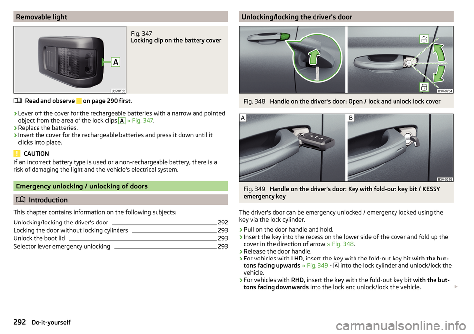
Removable lightFig. 347
Locking clip on the battery cover
Read and observe on page 290 first.
›
Lever off the cover for the rechargeable batteries with a narrow and pointed
object from the area of the lock clips
A
» Fig. 347 .
›
Replace the batteries.
›
Insert the cover for the rechargeable batteries and press it down until it
clicks into place.
CAUTION
If an incorrect battery type is used or a non-rechargeable battery, there is a
risk of damaging the light and the vehicle's electrical system.
Emergency unlocking / unlocking of doors
Introduction
This chapter contains information on the following subjects:
Unlocking/locking the driver's door
292
Locking the door without locking cylinders
293
Unlock the boot lid
293
Selector lever emergency unlocking
293Unlocking/locking the driver's doorFig. 348
Handle on the driver's door: Open / lock and unlock lock cover
Fig. 349
Handle on the driver's door: Key with fold-out key bit / KESSY
emergency key
The driver's door can be emergency unlocked / emergency locked using the
key via the lock cylinder.
›
Pull on the door handle and hold.
›
Insert the key into the recess on the lower side of the cover and fold up the
cover in the direction of arrow » Fig. 348.
›
Release the door handle.
›
For vehicles with LHD, insert the key with the fold-out key bit with the but-
tons facing upwards » Fig. 349 -
into the lock cylinder and unlock/lock the
vehicle.
›
For vehicles with RHD, insert the key with the fold-out key bit with the but-
tons facing downwards into the lock and unlock/lock the vehicle.
292Do-it-yourself
Page 295 of 336
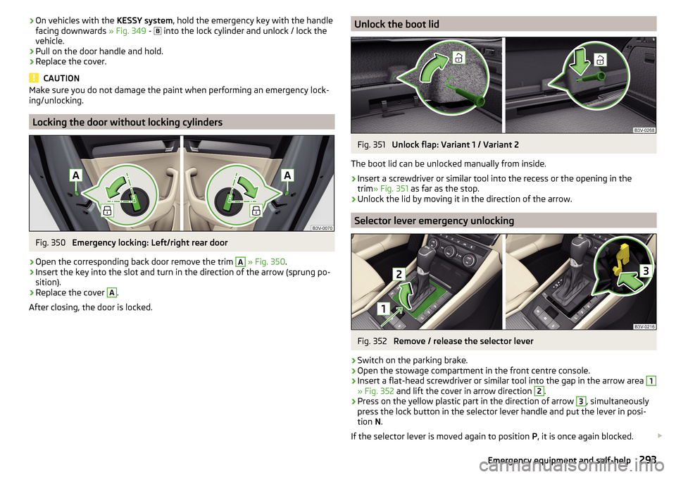
›On vehicles with the
KESSY system, hold the emergency key with the handle
facing downwards » Fig. 349 - into the lock cylinder and unlock / lock the
vehicle.›
Pull on the door handle and hold.
›
Replace the cover.
CAUTION
Make sure you do not damage the paint when performing an emergency lock-
ing/unlocking.
Locking the door without locking cylinders
Fig. 350
Emergency locking: Left/right rear door
›
Open the corresponding back door remove the trim
A
» Fig. 350 .
›
Insert the key into the slot and turn in the direction of the arrow (sprung po-
sition).
›
Replace the cover
A
.
After closing, the door is locked.
Unlock the boot lidFig. 351
Unlock flap: Variant 1 / Variant 2
The boot lid can be unlocked manually from inside.
›
Insert a screwdriver or similar tool into the recess or the opening in the
trim » Fig. 351 as far as the stop.
›
Unlock the lid by moving it in the direction of the arrow.
Selector lever emergency unlocking
Fig. 352
Remove / release the selector lever
›
Switch on the parking brake.
›
Open the stowage compartment in the front centre console.
›
Insert a flat-head screwdriver or similar tool into the gap in the arrow area
1
» Fig. 352 and lift the cover in arrow direction
2
.
›
Press on the yellow plastic part in the direction of arrow
3
, simultaneously
press the lock button in the selector lever handle and put the lever in posi-
tion N.
If the selector lever is moved again to position P, it is once again blocked.
293Emergency equipment and self-help
Page 299 of 336
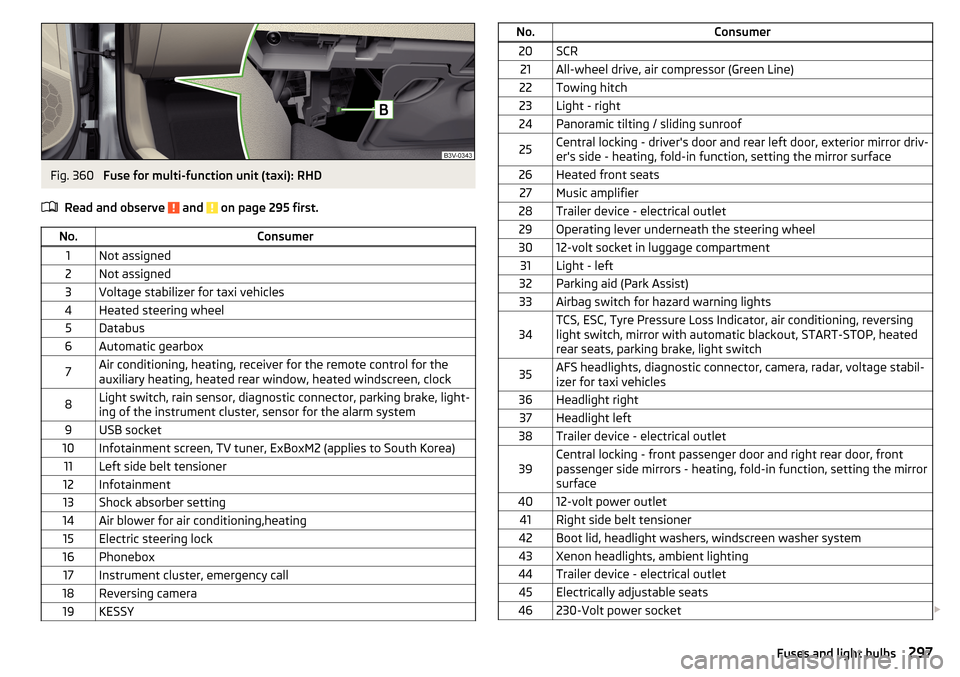
Fig. 360
Fuse for multi-function unit (taxi): RHD
Read and observe
and on page 295 first.
No.Consumer1Not assigned2Not assigned3Voltage stabilizer for taxi vehicles4Heated steering wheel5Databus6Automatic gearbox7Air conditioning, heating, receiver for the remote control for the
auxiliary heating, heated rear window, heated windscreen, clock8Light switch, rain sensor, diagnostic connector, parking brake, light-
ing of the instrument cluster, sensor for the alarm system9USB socket10Infotainment screen, TV tuner, ExBoxM2 (applies to South Korea)11Left side belt tensioner12Infotainment13Shock absorber setting14Air blower for air conditioning,heating15Electric steering lock16Phonebox17Instrument cluster, emergency call18Reversing camera19KESSYNo.Consumer20SCR21All-wheel drive, air compressor (Green Line)22Towing hitch23Light - right24Panoramic tilting / sliding sunroof25Central locking - driver's door and rear left door, exterior mirror driv-
er's side - heating, fold-in function, setting the mirror surface26Heated front seats27Music amplifier28Trailer device - electrical outlet29Operating lever underneath the steering wheel3012-volt socket in luggage compartment31Light - left32Parking aid (Park Assist)33Airbag switch for hazard warning lights34TCS, ESC, Tyre Pressure Loss Indicator, air conditioning, reversing
light switch, mirror with automatic blackout, START-STOP, heated
rear seats, parking brake, light switch35AFS headlights, diagnostic connector, camera, radar, voltage stabil-
izer for taxi vehicles36Headlight right37Headlight left38Trailer device - electrical outlet39Central locking - front passenger door and right rear door, front
passenger side mirrors - heating, fold-in function, setting the mirror
surface4012-volt power outlet41Right side belt tensioner42Boot lid, headlight washers, windscreen washer system43Xenon headlights, ambient lighting44Trailer device - electrical outlet45Electrically adjustable seats46230-Volt power socket 297Fuses and light bulbs
Page 316 of 336
Selector lever emergency unlocking293
Selector lever lock207
Start and run208
Tiptronic208
Warning light39
Automatic transmission206
AUX90, 150
Settings135
Auxiliary heating (auxiliary heating and ventila- tion)
118
Avoiding damage to your vehicle211
B
Battery Changing batteries for the removable light
292
Changing in key290, 291
Replace the battery in the remote control in the auxiliary heating
291
Belts15
Belt tensioners17
Bluetooth A2DP / AVRCP
133
Name133
on / off133
Paired external devices133
rSAP167
Set140
set to133, 136
Set to133
Switch on/off140
Update131, 134
Updates140
Visibility133, 140
Bluetooth Player151
Bluetooth profile164
Bluetooth® update164
Bonnet Close
269
Open269
Boot Class N1 vehicles109
Boot lid59
Automatic locking59
Contactless open/close61
Open/close59, 60
See boot lid59
Boot lid contactless open/close61
Brake Assist (HBA)214
Brake booster203
Brake fluid273
Check273
specification273
Brake linings Warning light
38
Brake pads new
203
Brake pedal (automatic gearbox) Warning light
38
Brakes Brake booster
203
Brake fluid273
Braking and stabilisation systems212
Information on braking203
Parking brake203
Running in209
Warning light35
Brake system212
Breakdown call168
Broadcasting143
See main menu142
Bulbs Replacing
299
Buttons on the driver door Electric windows
62
C
Call list Call list
170
CameraSee reversing camera221
CAR198
Car battery automatic consumer shutdown
273
Check condition274
Cover274
Disconnecting and reconnecting275
Replacing275
Winter operation274
CAR button198
Car care260
Exterior263
Interior263
Car computer see multifunction display
46
Care and maintenance256
Cargo element106
CAR menu198
Car park184
Carrier112
Car wash260
Exterior263
Panes263
CD149
Central locking53
Problems57
Central locking button55
Changing Batteries for the removable light
292
Battery290, 291
Wheels282
Windscreen wiper blades295
Changing a wheel282
Changing gear Selector lever
207
Tiptronic208
Charging a vehicle battery275
314Index
Page 318 of 336
Dipstick271
Display125
Cardinal points43
Coolant temperature32
Fuel level33
Gear changes44
In the instrument cluster43
MAXI DOT48
Rear centre console33
Service intervals49
Display in Infotainment Driving data
46
Disposal Acceptance and recycling of used vehicles
258
Distance warning238
Warning light42
Diverting calls136
Door Child safety lock
57
Emergency locking293
Emergency locking of the driver's door292
Open / Close57
Door warning43
Drive Driving through water
211
DriveGreen210
Driving Emissions
305
Fuel consumption305
Maximum speed309
through water211
Driving data Show
46
Driving mode240
Adaptive Chassis Control (DCC)240
Comfort241
Eco240
Individual241
Mode selection and Infotainment display241
Normal241
Settings for individual mode242
Sports241
Driving Mode Selection240
DSR214
DVD149
DVD-Video Set to
135
Dynamic Light Assist71
Dynamic Road Sign Display Additional display
248
Information messages248
Malfunctions248
Operation247
Settings in Infotainment247
Dynamic route switch on / off
197
E
Economical driving
209
Economy mode42
ECO TIP43
Eco tips43
Edit route192
EDS214
Electrical boot lid set the top position of the lid
61
Electric boot lid Force limiter
59
Manual operation59
Open/close60
Electric parking brake203
Electric power windows62, 63
Malfunctions64
Electric tail gate Malfunctions
61
Electric windows Buttons on the driver door
62
Electronic Differential Lock (EDL, XDS)214
Electronic immobilizer199
Elevation180
emergency Jump-starting
288
Starting the engine / stopping the push of a button
201
Emergency Changing a wheel
282
Hazard warning light system70
Jump-starting287
Selector lever release293
Starting the engine / stopping the engine at the push of a button
200
Towing the using the tow hitch290
Towing the vehicle288
Tyre repair285
Unlocking/locking the door292
Unlocking / locking the door293
Emergency call168
Emergency equipment Fire extinguisher
281
First aid kit280
Jack281
Reflective vest280
Vehicle tool kit281
Warning triangle280
Emission control system36
Emissions305
Engine Information messages
39
Running in209
Engine compartment268
Brake fluid273
Coolant271
Engine oil270
Overview269
Vehicle battery273
Windscreen washer fluid270
Engine drag torque control (MSR)213
Engine number303
316Index
Page 320 of 336
I
I-PAD holder
99
I-Size27
Ignition lock200
Images Display
135
Main menu153
safe removal of the data source133
Select Image Source153
service154
Set to135
Image viewer153
Immobilizer199
Import contacts136, 141
Import destinations186
Import my destinations186
Inertia reels17
Information about the towing process288
Information call168
Information system43
Auto Check Control43
Door alarm43
Eco tips43
Gear recommendation44
MAXI DOT display48
Multifunction display46
Service interval display49
Infotainment Auxiliary heating (auxiliary heating and ventila-tion)
119
Restart126
Software update131
Infotainment language132, 140
Infotainment menu CAR
198
Media (video)155
Sound131
TV tuner156
Infotainment menus127
Infotainment operation125
Infotainment screen125
Infotainment operation using an application in the external device
128
Infotainment screen132, 139
Areas125
important information124
Important information124
keyboard126
Maintenance124
Operation125
Input screen Language characters
140
Input screen with keyboard126
Instrument cluster32
Auto Check Control44
Warning lights33
Interior light73
Interior lighting72, 73
Ambient lighting73
Interior monitor58
Intermediate target190
ISOFIX26
J
Jack
281
- fit284
Jukebox151
Jump-starting287, 288
K
KESSY Unlock / lock
55
key Starting / stopping the engine
200
Switch on/off ignition200
Key Changing battery
290, 291
Take out emergency key54
keyboard126
L
L-band
135
Lamp failure Warning light
41
Lamps Warning light
41
Lan Departure Warning Activation / deactivation
245
Lane Assist Malfunctions
245
See lane departure warning243
Settings in Infotainment243
Warning light38
Lane Departure Warning243
Operation244
Settings in Infotainment243
Lane recommendation191
Language characters132
Last destinations184
Latitude180
LEAVING HOME70
Lever ACC
235
Cruise control230
Front Assist239
Operation of the information system45
Speed limiter with ACC232
Speed limiter with GRA232
Turn signal/main beam68
Windscreen wipers76, 77
Liability for defects5
Light66
Cockpit72
COMING HOME / LEAVING HOME70
Daytime running lights67
Flash68
Fog lights/rear fog light69
Fog lights with CORNER function70
318Index