engine SKODA YETI 2011 1.G / 5L Owner's Guide
[x] Cancel search | Manufacturer: SKODA, Model Year: 2011, Model line: YETI, Model: SKODA YETI 2011 1.G / 5LPages: 252, PDF Size: 3.61 MB
Page 39 of 252
Remote control
Description You can use the remote control key:
●
to unlock and lock the car,
● unlocking boot lid,
● electrically open and close the windows.
The transmitter with the battery is housed in the handle of the remote control
key. The receiver is located in the interior of the car. The operating range of the
remote control key is approx. 10 m. But this range of the remote control can be
reduced if the batteries are weak.
The key has a fold-open key bit which can be used for unlocking and locking the
car manually and also for starting the engine.
If a lost key is replaced or if the receiver unit has been repaired or a new unit in-
stalled, it is then necessary for an authorised
ŠKODA Service Partner to initialise
the system. Only after this is it possible to again use the remote control key. Note
● The remote control is automatically deactivated when the ignition is switched
on.
● The operation of the remote control may temporarily be affected by interfer-
ence from transmitters close to the car and which operate in the same frequency
range (e.g. mobile phone, TV transmitter).
● The battery must be replaced if the central locking or anti-theft alarm system
does react to the remote control at less than 3
metres away ⇒ page 31.
● If the driver door is opened, the vehicle cannot be locked using the remote
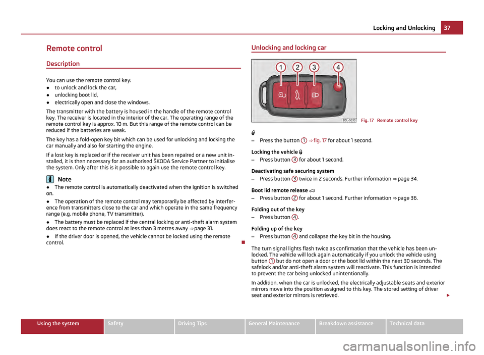
control. Unlocking and locking car Fig. 17 Remote control key
– Press the button 1
⇒ fig. 17 for about 1 second.
Locking the vehicle
– Press button 3 for about 1 second.
Deactivating safe securing system
– Press button 3 twice in 2 seconds. Further information
⇒
page 34.
Boot lid remote release
– Press button 2 for about 1 second. Further information
⇒
page 36.
Folding out of the key
– Press button 4 .
Folding up of the key
– Press button 4 and collapse the key bit in the housing.
The turn signal lights flash twice as confirmation that the vehicle has been un-
locked. The vehicle will lock again automatically if you unlock the vehicle using
button 1 but do not open a door or the boot lid within the next 30 seconds. The
safelock and/or anti-theft alarm system will reactivate. This function is intended
to prevent the car being unlocked unintentionally.
In addition, when the car is unlocked, the electrically adjustable seats and exterior
mirrors move into the position assigned to this key. The stored setting of driver
seat and exterior mirrors is retrieved. £ 37
Locking and Unlocking Using the system Safety Driving Tips General Maintenance Breakdown assistance Technical data
Page 51 of 252
The warning light
lights up in the instrument cluster when the fog lights are
switched on ⇒
page 22.
Fog lights with the function “CORNER” The fog lights with the function “CORNER” are designed for a bet-
ter illumination of the surrounding area near the vehicle when
corning, parking etc.
The fog lights with the function
“CORNER” are adjusted according to the steering
angle or after switching on the turn signal light 1)
in the following circumstances:
● the vehicle is stationary and the engine is running or it moves with a speed of
maximum 40 km/h;
● the daylight driving lights are not switched on;
● the low beam is switched on or the light switch is in the position
and the
intensity of the ambient light causes the low beam to be switched on;
● the fog lights are not switched on;
● no reverse gear is engaged. Note
If you engage the reverse gear during the active function “CORNER”, both fog
lights illuminate.
Rear fog light Switching on the rear fog light
–
First of all turn the light switch into position or ⇒
fig. 26 .
– Pull the light switch into position 2 .
The warning light
lights up in the instrument cluster when the rear fog light is
switched on ⇒ page 22.
Only the rear fog light of the trailer lights up if the vehicle has a factory-fitted
towing device or a towing device from ŠKODA original accessories and when you
are towing a trailer which is fitted with the rear fog light. The rear fog light is located in the rear light array on the driver's side. CAUTION
The rear fog light should only be switched on if visibility is particularly poor (con-
form with any varying legal provisions) to avoid dazzling vehicles behind your ve-
hicle.
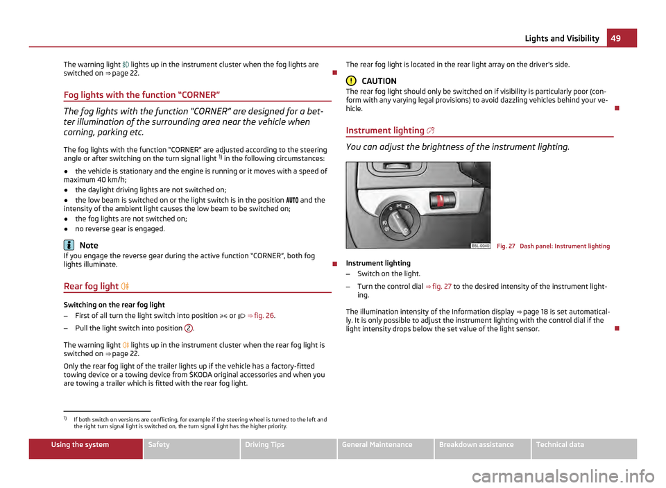
Instrument lighting You can adjust the brightness of the instrument lighting.
Fig. 27 Dash panel: Instrument lighting
Instrument lighting
– Switch on the light.
– Turn the control dial ⇒
fig. 27 to the desired intensity of the instrument light-
ing.
The illumination intensity of the Information display ⇒ page 18 is set automatical-
ly. It is only possible to adjust the instrument lighting with the control dial if the
light intensity drops below the set value of the light sensor. 1)
If both switch on versions are conflicting, for example if the steering wheel is turned to the left and
the right turn signal light is switched on, the turn signal light has the higher priority. 49
Lights and Visibility Using the system Safety Driving Tips General Maintenance Breakdown assistance Technical data
Page 55 of 252
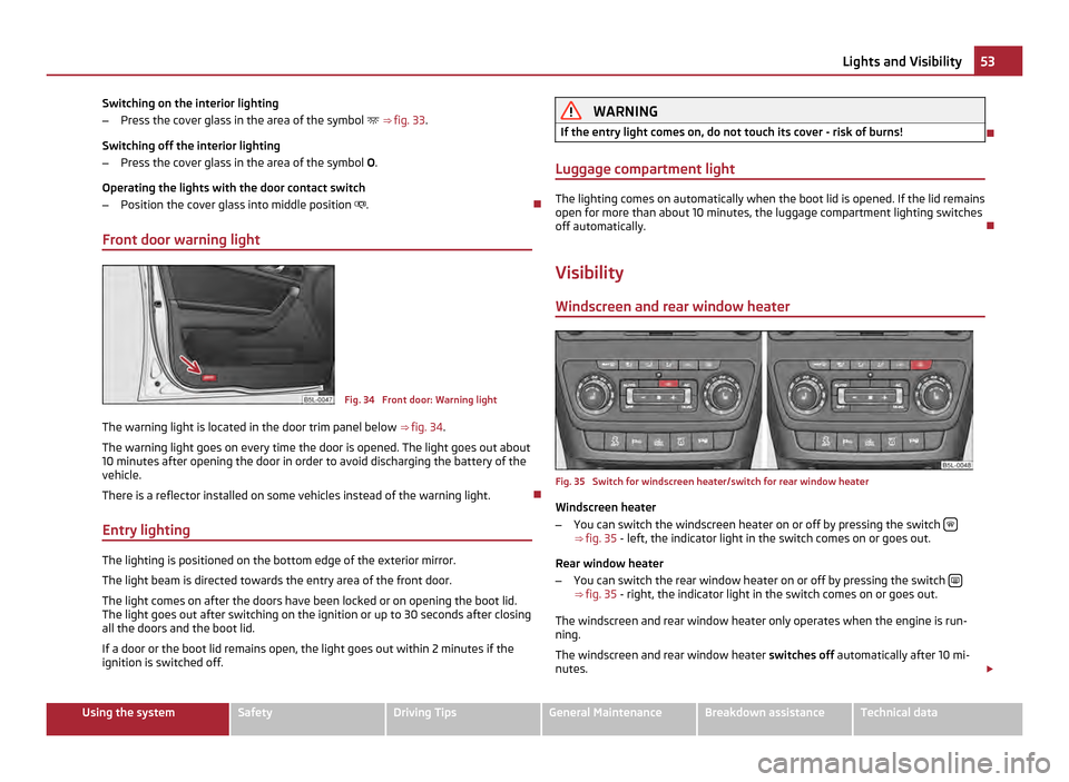
Switching on the interior lighting
–
Press the cover glass in the area of the symbol ⇒ fig. 33.
Switching off the interior lighting
– Press the cover glass in the area of the symbol O.
Operating the lights with the door contact switch
– Position the cover glass into middle position .
Front door warning light Fig. 34 Front door: Warning light
The warning light is located in the door trim panel below ⇒ fig. 34.
The warning light goes on every time the door is opened. The light goes out about
10 minutes after opening the door in order to avoid discharging the battery of the
vehicle.
There is a reflector installed on some vehicles instead of the warning light.
Entry lighting The lighting is positioned on the bottom edge of the exterior mirror.
The light beam is directed towards the entry area of the front door.
The light comes on after the doors have been locked or on opening the boot lid.
The light goes out after switching on the ignition or up to 30 seconds after closing
all the doors and the boot lid.
If a door or the boot lid remains open, the light goes out within 2 minutes if the
ignition is switched off. WARNING
If the entry light comes on, do not touch its cover - risk of burns!
Luggage compartment light The lighting comes on automatically when the boot lid is opened. If the lid remains
open for more than about 10 minutes, the luggage compartment lighting switches
off automatically.
Visibility Windscreen and rear window heater Fig. 35 Switch for windscreen heater/switch for rear window heater
Windscreen heater
– You can switch the windscreen heater on or off by pressing the switch ⇒
fig. 35 - left, the indicator light in the switch comes on or goes out.
Rear window heater
– You can switch the rear window heater on or off by pressing the switch ⇒
fig. 35 - right, the indicator light in the switch comes on or goes out.
The windscreen and rear window heater only operates when the engine is run-
ning.
The windscreen and rear window heater switches off automatically after 10
mi-
nutes. £ 53
Lights and Visibility Using the system Safety Driving Tips General Maintenance Breakdown assistance Technical data
Page 56 of 252
For the sake of the environment
As soon as the window is de-iced or free from mist, the heating should be switch-
ed off. The reduced current consumption will have a favourable effect on fuel
economy ⇒ page 166
, Saving electricity.Note
● If the on-board voltage drops, the front and rear window heater switches off
automatically, in order to provide sufficient electrical energy for the engine con-
trol.
● The position and the shape of the switch can differ depending on equipment
installed in the vehicle.
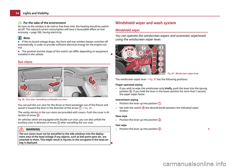
Sun visors Fig. 36 Sun visor: Swivelling out/double sun visor
You can pull the sun visor for the driver or front passenger out of the fixture and
swivel it toward the door in the direction of the arrow
1
⇒
fig. 36 .
The vanity mirrors in the sun visors are provided with covers. Push the cover in di-
rection of arrow 2 .
On vehicles which are equipped with double sun visor, you can also unfold the
auxiliary visor in direction of arrow 3 after swivelling the sun visor.
WARNING
The sun visors must not be swivelled to the side windows into the deploy-
ment area of the head airbags if any objects, such as ball-point pens etc. are
attached to them. This might result in injuries to the occupants if the head air-
bag is deployed. Windshield wiper and wash system
Windshield wiper You can operate the windscreen wipers and automatic wipe/wash
using the windscreen wiper lever. Fig. 37 Windscreen wiper lever
The windscreen wiper lever ⇒
fig. 37 has the following positions:
Finger-operated wiping
– If you wish to wipe the windscreen only briefly, push the lever into the sprung
position 4 . If you hold the lever in the lower position for more than 1 second,
the wiper wipes faster.
Intermittent wiping
– Position the lever up into position 1 .
– Set with the switch A the desired break between the individual wiper
strokes.
Slow wipe
– Position the lever up into position 2 .
Fast wipe
– Position the lever up into position 3 .
£54
Lights and Visibility
Page 58 of 252
CAUTION
● In cold temperatures and in winter, check before the trip or before switching
on the ignition that the wiper blades are not frozen. Switching on windscreen
wipers when the blades are frozen to the windscreen may result in damage both
to the blades and the motor of the windscreen wipers!
● If you switch off the ignition while the windscreen wipers are on, the wipers
will sweep in the same mode the next time the ignition is switched on. At low
temperatures, the wipers may freeze to the window between switching off the ig-
nition and the next time you switch the ignition on again.
● Carefully detach frozen wiper blades from the front or rear window.
● Remove snow and ice from the window wipers before driving. Note
● If the slower 2 ⇒ fig. 37 or the faster
3 wiper setting is switched on and the
vehicle speed decreases to below 4 km/h, the lower wiper step is switched on au-
tomatically. At a speed increase of more than 8 km/h the previous wiper setting is
established again.
● If there is an obstacle on the windscreen, the wiper will try to push away the
obstacle. If the obstacle continues to block the wiper, the wiper stops automati-
cally after 5 attempts to eliminate the obstacle, in order to avoid a damage to the
wiper. Remove the obstacle and and switch on the wiper again.
● The windscreen washer nozzles for the windscreen are heated when the en-
gine is running and the outside temperature is less than +10 °C.
● The content of the windscreen wiper reservoir is 3 litres. On vehicles which are
equipped with a headlight cleaning system, the content of the reservoir is 5.5
li-
tres. On vehicles fitted with auxiliary heating, the content of the windscreen wiper
reservoir is 4.5 litres.
Automatic rear window wiper If the windshield wiper is in position
2 or
3 , the rear view window is wiped ev-
ery 30 seconds if the vehicle's speed exceeds 5
km/h.
When the rain sensor is active (the lever is in the position 1 ) the function is only
active if the front window wipers continue to operate (no break between each
wiping process). Activation/deactivation
The function of the automatic rear window wiper is activated/deactivated in the
information display in the menu:
■ Settings
■ Lights & Vision
■Rear wiper Note
The function of the automatic rear window wiper is only valid for vehicles which
are equipped with the information display. The function is activated in the factory.
Alternative park position of the rear window wiper Each time after switching off the engine for the second time, the wiper blade of
the rear window wiper is tilted. Thus, the life of the wiper blade is prolonged.
Activation/deactivation
– Switch on the ignition.
– Push the operating level into the position 6
⇒ fig. 37 five times in succession
within 5 seconds.
– Switch off the ignition. After switching on the ignition again, the alternative
park position of the rear window wiper is activated/deactivated.
Headlight cleaning system The headlights are being cleaned after the windscreen has been sprayed for the
first time and fifth time, the low beam or main beam are switched on and the
windscreen wiper lever was held in the position 5
⇒ fig. 37 for about 1 second.
The headlight washer nozzles are moved forward out of the bumper by the water
pressure for cleaning the headlights.
You should remove stubborn dirt (such as insect residues) from the headlight len-
ses at regular intervals, for example when refuelling. Please refer to the following
guidelines ⇒
page 183, The headlight lenses.
You should remove any snow from the fixtures of the washer nozzles and clear ice
in winter with a de-icing spray in order to ensure proper operation of the cleaning
system. £56
Lights and Visibility
Page 61 of 252
The exterior mirror heater only operates when the engine is running and up to an
outside temperature of +20 °C.
Adjusting left and right exterior mirrors simultaneously
– Turn the rotary knob to position . The movement of the mirror surface is iden-
tical to the movement of the rotary knob.
The adjustment of both mirrors simultaneously or each individual mirror is possi-
ble in the Information display ⇒
table on page 20 in the menu point Mirror adjust.
(Mirror adjust.).
Adjusting the right-hand exterior mirror
– Turn the rotary knob to position . The movement of the mirror surface is iden-
tical to the movement of the rotary knob.
Switching off operating control
– Turn the rotary knob to position .
Folding in both exterior mirrors
– Turn the rotary knob to position .
Fold in the exterior mirrors using the remote control key
– If all the windows are closed, press the unlock button 3 on the radio remote
control ⇒ fig. 17 for approx. 2 seconds.
Tilting surface of front passenger exterior mirror
On vehicles fitted with a memory for the driver seat, the surface of the mirror tilts
down slightly when the rear gear is engaged and the rotary knob is in the posi-
tion ⇒ fig. 41 . This provides an aid in seeing the kerb of the pavement when park-
ing the car.
The mirror returns into its initial position, after the rotary knob is moved out of the
position and put into another position or if the speed is more than 15 km/h.
Memory for exterior mirrors
On vehicles fitted with a memory for the driver seat, the relevant setting of the
exterior mirror is also stored automatically when the seat position is stored
⇒ page 63. WARNING
● Convex (curved outward) or a spherical exterior mirrors increase the vision
field. They do, however, make objects appear smaller in the mirror. These mir-
rors are only of limited use, therefore, for estimating distances to the follow-
ing vehicles.
● Use whenever possible the interior rear mirror, for estimating the distan-
ces to the following vehicles. Note
● If the exterior mirrors are folded in using the remote control of the vehicle key,
these are folded back into the driving position after opening the door or switching
on the ignition.
● If the exterior mirrors are folded in using the rotary knob ⇒
fig. 41, they can on-
ly be folded back into the driving position using the rotary knob.
● If the exterior mirrors were folded in using the remote control of the vehicle
key and if the rotary knob was in the fold-in position before switching on the igni-
tion, the mirrors remain in the fold-in position the next time the ignition is switch-
ed on. Folding back into the driving position is performed by actuating the rotary
knob in a different position from the fold-in position.
● Do not touch the surfaces of the exterior mirrors if the exterior mirror heater is
switched on.
● You can set the exterior mirrors by hand, if the power setting function fails at
any time, by pressing on the edge of the mirror surface.
● Contact your specialist garage if a fault exists with the power setting of the
exterior mirrors.
Automatic dimming exterior mirror on the driver's side The exterior mirror on the driver's side is dimmed together with the interior mirror.
If the automatic dimming is switched on, the mirror dims automatically depending
on the light striking the mirror from the rear.
When the interior lights are switched on or the reverse gear is engaged, the mirror
always moves back into the basic position (not dimmed). £ 59
Lights and Visibility Using the system Safety Driving Tips General Maintenance Breakdown assistance Technical data
Page 72 of 252
CAUTION
● You should not kneel on the seats or otherwise apply pressure at specific
points in order to avoid damaging the heating elements of the seat heaters.
● Do not use the seat heating if the seats are not occupied by persons or if ob-
jects are fastened or stored on them, for example a child seat, a bag etc. A fault of
the heating elements in the seat heating can occur.
● Do not clean the seats moist ⇒ page 184 .Note
● The seat heating should only be switched on when the engine is running. This
has a significant effect of saving on the battery capacity.
● If the on-board voltage drops, the seat heating is switched off automatically,
in order to provide sufficient electrical energy for the engine control.
Pedals Concerning a secure depressing of the pedal, you should use only footmats from
the
ŠKODA Original Accessories.
Operation of the pedals must not be hindered! WARNING
● Greater pedal distances may be needed when there is a fault in the brake
system.
● Do not place any footmats or other additional floor coverings in the area of
the pedals in order to ensure that all the pedals can be fully depressed and are
able to return unobstructed to their initial position - risk of accident!
● There must be no objects on the floor which could roll under the pedals.
You would then no longer be able to apply the brakes, operate the clutch or
accelerator - risk of accident!
luggage compartment
Loading the luggage compartment Please observe the following in the interest of having good handling characteris-
tics of your vehicle: –
Distribute the items of luggage as evenly as possible.
– Place heavy objects as far forward as possible.
– Attach the items of luggage to the lashing eyes or the fixing net ⇒
page 71.
In the event of an accident, there is such a high kinetic energy which is produced
by small and light objects that they can cause severe injuries. The magnitude of
the kinetic energy depends on the speed at which the vehicle is travelling and on
the weight of the object. The speed at which the vehicle is travelling is in this case
the more significant factor.
Example: In the event of a frontal collision at a speed of 50 km/h, an unsecured
object with a weight of 4.5 kg produces an energy, which corresponds to 20 times
its own weight. This means that it results in a weight of approx. 90 kg. You can
imagine the injuries that can occur, if this “bullet” is flying through the interior
compartment and hits an occupant. WARNING
● Store the objects in the luggage compartment and attach them to the
lashing eyes.
● Loose objects in the passenger compartment can be thrown forward dur-
ing a sudden manoeuvre or in case of an accident and can injure the occupants
or other oncoming traffic. This risk is still increased, if the objects which are
flying around are hit by a deployed airbag. In this case, the objects which are
thrown back can injure the occupants - hazard.
● Please note that the handling properties of your vehicle may be affected
when transporting heavy objects as a result of the displacement of the centre
of gravity. The speed and style of driving must be adjusted accordingly.
● The items carried in the luggage compartment should be stored in such a
way that no objects are able to slip forward if there are any sudden driving or
braking manoeuvres undertaken - risk of injury!
● Never drive with the boot lid fully opened or slightly ajar otherwise ex-
haust gases may get into the interior of the vehicle - risk of poisoning!
● On no account exceed the permissible axle loads and the permissible gross
weight of the vehicle - risk of accident!
● Never transport occupants in the luggage compartment! CAUTION
Please ensure that the heating elements of the rear window heater are not dam-
aged as a result of objects sliding in this area. £70
Seats and Stowage
Page 82 of 252
CAUTION
Always use matching plugs to avoid damaging the power socket. Note
● Connecting electrical components when the engine is not running will drain
the battery of the vehicle - risk of battery draining!
● Further information ⇒ page 207, Accessories, changes and replacement of
parts .
Power socket in the luggage compartment Fig. 75 Luggage compartment: Power
socket
– Open the cover of the power socket ⇒
fig. 75.
– Connect the plug of the electrical appliance to the socket.
You can only use the power socket for the connection of approved electrical ac-
cessories with a power uptake up to 120 watts. The vehicle battery will be dis-
charged in the process if the engine is stationary.
The same remarks apply here as for ⇒ page 79, Cigarette lighter, power sockets
.
Further information ⇒ page 207, Accessories, changes and replacement of parts.
Storage compartments
Overview You will find the following storage facilities in your vehicle: Storage compartment on the front passenger side ⇒ page 80
Storage compartment on the dash panel ⇒
page 81 Stowage compartment in front centre console ⇒
page 82 Stowage compartment for spectacles ⇒
page 82 Storage compartment in the front and rear doors ⇒
page 82 Stowage compartment below front passenger seat ⇒
page 83 Front seat armrest with stowage compartment ⇒
page 83 Stowage compartment in rear centre console ⇒ page 84
Storage compartments in the luggage compartment ⇒ page 84
Flexible storage compartment ⇒ page 84
Clothes hooks ⇒ page 85
Through-loading bag ⇒ page 85
WARNING
● Please do not place anything on top of the dash panel. Such objects might
slide or fall down when driving (when accelerating or cornering) and may dis-
tract you from concentrating on the traffic situation - risk of accident!
● Ensure that when driving no objects from the centre console of from other
storage possibilities may get into the footwell of the driver. You would then
no longer be able to apply the brakes, operate the clutch or accelerator - risk
of accident!
Storage compartment on the front passenger side Fig. 76 Dash panel: Storage compart-
ment on the front passenger side
£80
Seats and Stowage
Page 88 of 252
Heating and air conditioning system
Introduction
Description and information The heating effect is dependent upon the coolant temperature, thus full heat out-
put only occurs when the engine has reached its operating temperature.
If the cooling system is switched on, the temperature and air humidity drops in
the vehicle. The well-being of the occupants of the car is enhanced as a result of
this particularly at high outside temperatures and a high air humidity. The system
prevents the windows misting up during the cold season of the year.
It is possible to briefly activate recirculated air mode in order to enhance the cool-
ing effect - air-conditioning system ⇒
page 89, Climatronic ⇒ page 92.
The air inlet in front of the windscreen must be free of ice, snow or leaves in order
to ensure that the heating and cooling systems operate properly.
After switching on the cooling Condensation from the evaporator of the air condi-
tioning may drip down and form a puddle below the vehicle. This is quite normal
and not an indication of a leak! WARNING
● For your own safety and that of other road users, ensure that all the win-
dows are free of ice, snow and misting. Please familiarize yourself about how
to correctly operate the heating and ventilation systems, how to demist and
defrost the windows, as well as with the cooling mode.
● You should not leave recirculated air mode on over a longer period of time,
as
“stale” air may result in fatigue in the driver and occupants, divert your at-
tention and also cause the windows to mist up. The risk of having an accident
increases. Switch recirculated air mode off as soon as the windows begin
misting up. Note
● The used air streams out through the air removal openings in the luggage
compartment.
● We recommend that you do not smoke in the vehicle when the recirculating air
mode is operating since the smoke which is drawn at the evaporator from the in-
terior of the vehicle forms deposits in the evaporator of the air conditioning sys- tem. This produces a permanent odour when the air conditioning system is oper-
ating which can only be eliminated through considerable effort and expense (re-
placement of compressor).
● Please refer to the information regarding the recirculated air mode for heating
⇒
page 89 and/or for air-conditioning system ⇒ page 89 or Climatronic
⇒ page 92.
● To ensure that the heating and air conditioning systems work properly, do not
block up the air outlet vents with any objects.
Using the air conditioning system economically The compressor on the air conditioning system uses power from the engine when
in cooling mode which will effect the fuel consumption.
It recommended to open the windows or the doors of a vehicle for which the inte-
rior has been strongly heated through the effect of direct sunlight in order to al-
low the heated air to escape.
The cooling system should not be switched on while travelling when the window
is open.
The desired interior temperature can also be achieved without switching in the
cooling system just by switching to fresh air mode. For the sake of the environment
When you economize on fuel, you also reduce pollutant emissions.
Operational problems If the cooling system does not operate at outside temperatures higher than +5 °C,
there is a problem in the system. The reasons for this may be:
●
The fuse on the air conditioning system has blown. Check the fuse, replace it if
necessary ⇒ page 220.
● The cooling system has switched off automatically for a short time because
the coolant temperature of the engine is too hot ⇒ page 11.
If you are not able to rectify the operational problem yourself, or if the cooling ca-
pacity decreases, switch the cooling system off. Contact a specialist garage. 86
Heating and air conditioning system
Page 92 of 252
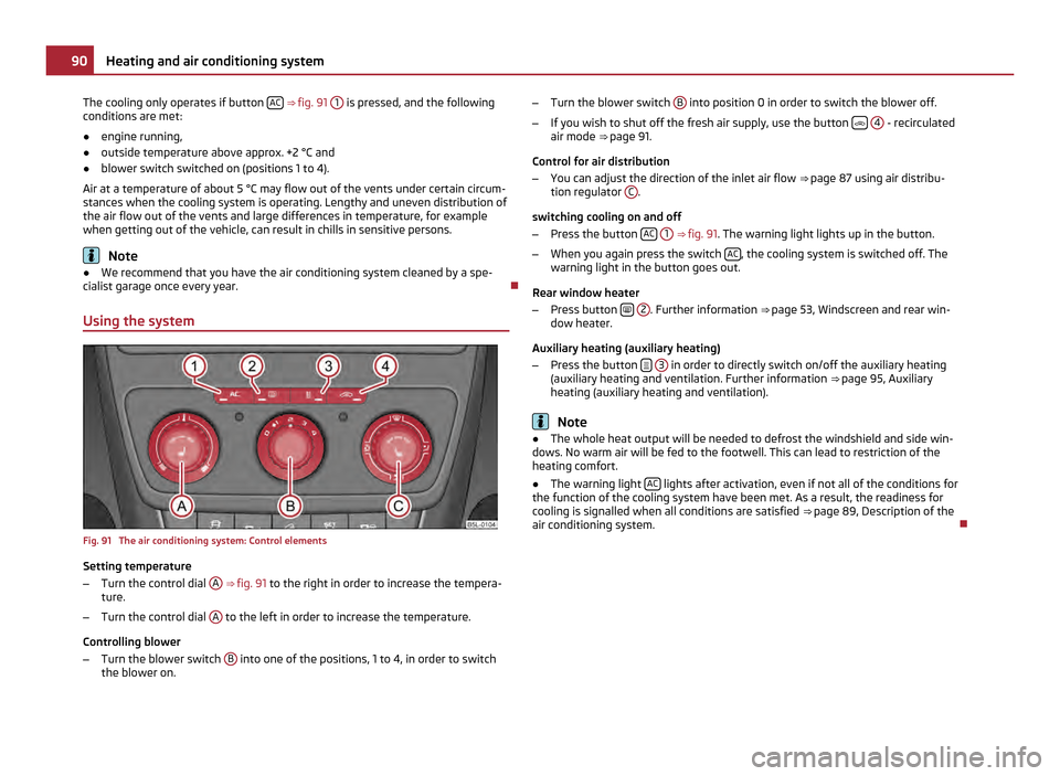
The cooling only operates if button
AC ⇒
fig. 91 1 is pressed, and the following
conditions are met:
● engine running,
● outside temperature above approx. +2 °C and
● blower switch switched on (positions 1 to 4).
Air at a temperature of about 5 °C may flow out of the vents under certain circum-
stances when the cooling system is operating. Lengthy and uneven distribution of
the air flow out of the vents and large differences in temperature, for example
when getting out of the vehicle, can result in chills in sensitive persons. Note
● We recommend that you have the air conditioning system cleaned by a spe-
cialist garage once every year.
Using the system Fig. 91 The air conditioning system: Control elements
Setting temperature
–
Turn the control dial A
⇒
fig. 91 to the right in order to increase the tempera-
ture.
– Turn the control dial A to the left in order to increase the temperature.
Controlling blower
– Turn the blower switch B into one of the positions, 1 to 4, in order to switch
the blower on. –
Turn the blower switch B into position 0 in order to switch the blower off.
– If you wish to shut off the fresh air supply, use the button
4 - recirculated
air mode ⇒
page 91.
Control for air distribution
– You can adjust the direction of the inlet air flow ⇒
page 87 using air distribu-
tion regulator C .
switching cooling on and off
– Press the button AC
1 ⇒
fig. 91 . The warning light lights up in the button.
– When you again press the switch AC , the cooling system is switched off. The
warning light in the button goes out.
Rear window heater
– Press button
2 . Further information
⇒
page 53, Windscreen and rear win-
dow heater.
Auxiliary heating (auxiliary heating)
– Press the button
3 in order to directly switch on/off the auxiliary heating
(auxiliary heating and ventilation. Further information ⇒ page 95
, Auxiliary
heating (auxiliary heating and ventilation). Note
● The whole heat output will be needed to defrost the windshield and side win-
dows. No warm air will be fed to the footwell. This can lead to restriction of the
heating comfort.
● The warning light AC lights after activation, even if not all of the conditions for
the function of the cooling system have been met. As a result, the readiness for
cooling is signalled when all conditions are satisfied ⇒
page 89, Description of the
air conditioning system. 90
Heating and air conditioning system