heater SKODA YETI 2011 1.G / 5L Owner's Manual
[x] Cancel search | Manufacturer: SKODA, Model Year: 2011, Model line: YETI, Model: SKODA YETI 2011 1.G / 5LPages: 252, PDF Size: 3.61 MB
Page 55 of 252
Switching on the interior lighting
–
Press the cover glass in the area of the symbol ⇒ fig. 33.
Switching off the interior lighting
– Press the cover glass in the area of the symbol O.
Operating the lights with the door contact switch
– Position the cover glass into middle position .
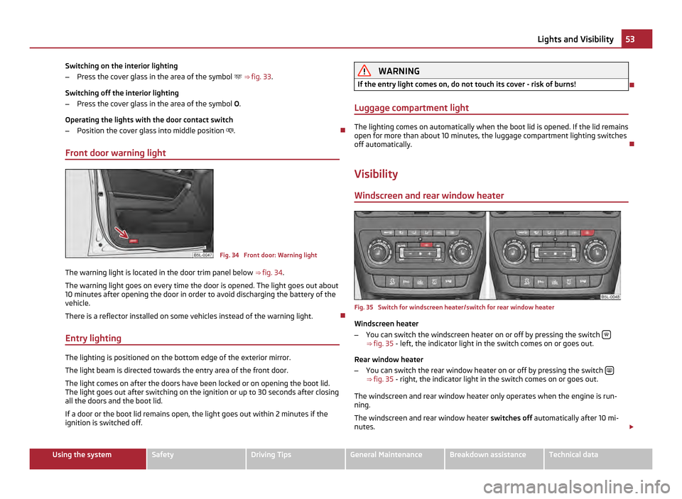
Front door warning light Fig. 34 Front door: Warning light
The warning light is located in the door trim panel below ⇒ fig. 34.
The warning light goes on every time the door is opened. The light goes out about
10 minutes after opening the door in order to avoid discharging the battery of the
vehicle.
There is a reflector installed on some vehicles instead of the warning light.
Entry lighting The lighting is positioned on the bottom edge of the exterior mirror.
The light beam is directed towards the entry area of the front door.
The light comes on after the doors have been locked or on opening the boot lid.
The light goes out after switching on the ignition or up to 30 seconds after closing
all the doors and the boot lid.
If a door or the boot lid remains open, the light goes out within 2 minutes if the
ignition is switched off. WARNING
If the entry light comes on, do not touch its cover - risk of burns!
Luggage compartment light The lighting comes on automatically when the boot lid is opened. If the lid remains
open for more than about 10 minutes, the luggage compartment lighting switches
off automatically.
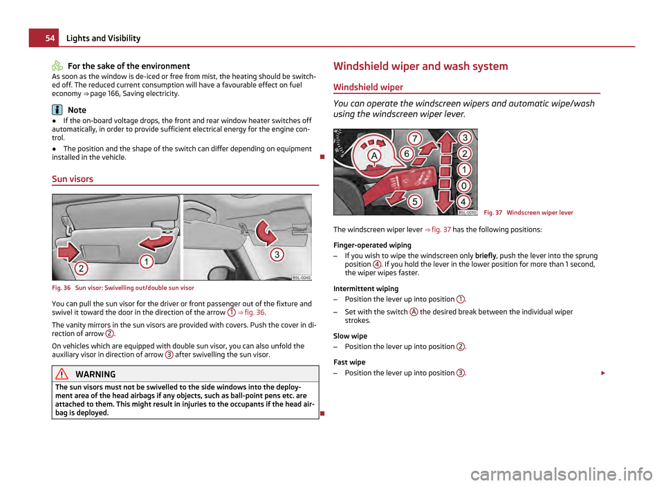
Visibility Windscreen and rear window heater Fig. 35 Switch for windscreen heater/switch for rear window heater
Windscreen heater
– You can switch the windscreen heater on or off by pressing the switch ⇒
fig. 35 - left, the indicator light in the switch comes on or goes out.
Rear window heater
– You can switch the rear window heater on or off by pressing the switch ⇒
fig. 35 - right, the indicator light in the switch comes on or goes out.
The windscreen and rear window heater only operates when the engine is run-
ning.
The windscreen and rear window heater switches off automatically after 10
mi-
nutes. £ 53
Lights and Visibility Using the system Safety Driving Tips General Maintenance Breakdown assistance Technical data
Page 56 of 252
For the sake of the environment
As soon as the window is de-iced or free from mist, the heating should be switch-
ed off. The reduced current consumption will have a favourable effect on fuel
economy ⇒ page 166
, Saving electricity.Note
● If the on-board voltage drops, the front and rear window heater switches off
automatically, in order to provide sufficient electrical energy for the engine con-
trol.
● The position and the shape of the switch can differ depending on equipment
installed in the vehicle.
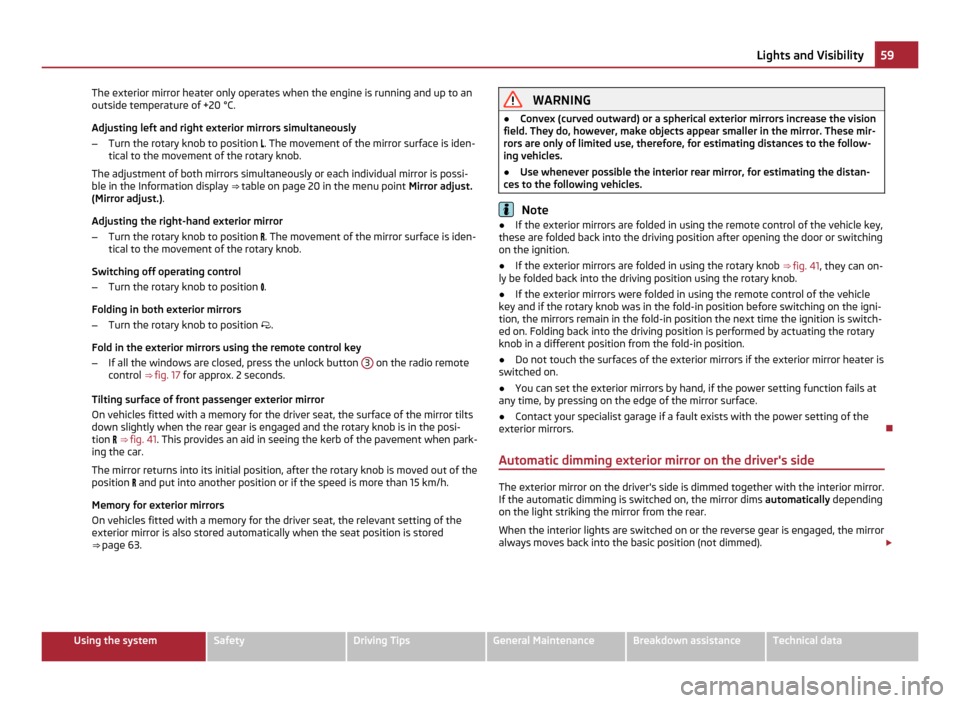
Sun visors Fig. 36 Sun visor: Swivelling out/double sun visor
You can pull the sun visor for the driver or front passenger out of the fixture and
swivel it toward the door in the direction of the arrow
1
⇒
fig. 36 .
The vanity mirrors in the sun visors are provided with covers. Push the cover in di-
rection of arrow 2 .
On vehicles which are equipped with double sun visor, you can also unfold the
auxiliary visor in direction of arrow 3 after swivelling the sun visor.
WARNING
The sun visors must not be swivelled to the side windows into the deploy-
ment area of the head airbags if any objects, such as ball-point pens etc. are
attached to them. This might result in injuries to the occupants if the head air-
bag is deployed. Windshield wiper and wash system
Windshield wiper You can operate the windscreen wipers and automatic wipe/wash
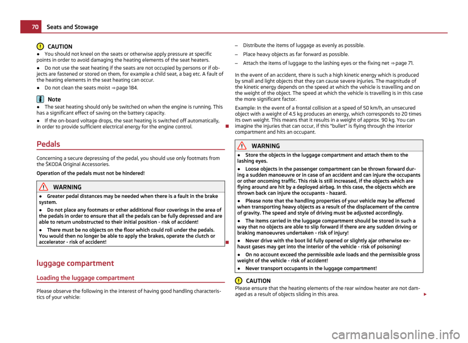
using the windscreen wiper lever. Fig. 37 Windscreen wiper lever
The windscreen wiper lever ⇒
fig. 37 has the following positions:
Finger-operated wiping
– If you wish to wipe the windscreen only briefly, push the lever into the sprung
position 4 . If you hold the lever in the lower position for more than 1 second,
the wiper wipes faster.
Intermittent wiping
– Position the lever up into position 1 .
– Set with the switch A the desired break between the individual wiper
strokes.
Slow wipe
– Position the lever up into position 2 .
Fast wipe
– Position the lever up into position 3 .
£54
Lights and Visibility
Page 61 of 252
The exterior mirror heater only operates when the engine is running and up to an
outside temperature of +20 °C.
Adjusting left and right exterior mirrors simultaneously
– Turn the rotary knob to position . The movement of the mirror surface is iden-
tical to the movement of the rotary knob.
The adjustment of both mirrors simultaneously or each individual mirror is possi-
ble in the Information display ⇒
table on page 20 in the menu point Mirror adjust.
(Mirror adjust.).
Adjusting the right-hand exterior mirror
– Turn the rotary knob to position . The movement of the mirror surface is iden-
tical to the movement of the rotary knob.
Switching off operating control
– Turn the rotary knob to position .
Folding in both exterior mirrors
– Turn the rotary knob to position .
Fold in the exterior mirrors using the remote control key
– If all the windows are closed, press the unlock button 3 on the radio remote
control ⇒ fig. 17 for approx. 2 seconds.
Tilting surface of front passenger exterior mirror
On vehicles fitted with a memory for the driver seat, the surface of the mirror tilts
down slightly when the rear gear is engaged and the rotary knob is in the posi-
tion ⇒ fig. 41 . This provides an aid in seeing the kerb of the pavement when park-
ing the car.
The mirror returns into its initial position, after the rotary knob is moved out of the
position and put into another position or if the speed is more than 15 km/h.
Memory for exterior mirrors
On vehicles fitted with a memory for the driver seat, the relevant setting of the
exterior mirror is also stored automatically when the seat position is stored
⇒ page 63. WARNING
● Convex (curved outward) or a spherical exterior mirrors increase the vision
field. They do, however, make objects appear smaller in the mirror. These mir-
rors are only of limited use, therefore, for estimating distances to the follow-
ing vehicles.
● Use whenever possible the interior rear mirror, for estimating the distan-
ces to the following vehicles. Note
● If the exterior mirrors are folded in using the remote control of the vehicle key,
these are folded back into the driving position after opening the door or switching
on the ignition.
● If the exterior mirrors are folded in using the rotary knob ⇒
fig. 41, they can on-
ly be folded back into the driving position using the rotary knob.
● If the exterior mirrors were folded in using the remote control of the vehicle
key and if the rotary knob was in the fold-in position before switching on the igni-
tion, the mirrors remain in the fold-in position the next time the ignition is switch-
ed on. Folding back into the driving position is performed by actuating the rotary
knob in a different position from the fold-in position.
● Do not touch the surfaces of the exterior mirrors if the exterior mirror heater is
switched on.
● You can set the exterior mirrors by hand, if the power setting function fails at
any time, by pressing on the edge of the mirror surface.
● Contact your specialist garage if a fault exists with the power setting of the
exterior mirrors.
Automatic dimming exterior mirror on the driver's side The exterior mirror on the driver's side is dimmed together with the interior mirror.
If the automatic dimming is switched on, the mirror dims automatically depending
on the light striking the mirror from the rear.
When the interior lights are switched on or the reverse gear is engaged, the mirror
always moves back into the basic position (not dimmed). £ 59
Lights and Visibility Using the system Safety Driving Tips General Maintenance Breakdown assistance Technical data
Page 72 of 252
CAUTION
● You should not kneel on the seats or otherwise apply pressure at specific
points in order to avoid damaging the heating elements of the seat heaters.
● Do not use the seat heating if the seats are not occupied by persons or if ob-
jects are fastened or stored on them, for example a child seat, a bag etc. A fault of
the heating elements in the seat heating can occur.
● Do not clean the seats moist ⇒ page 184 .Note
● The seat heating should only be switched on when the engine is running. This
has a significant effect of saving on the battery capacity.
● If the on-board voltage drops, the seat heating is switched off automatically,
in order to provide sufficient electrical energy for the engine control.
Pedals Concerning a secure depressing of the pedal, you should use only footmats from
the
ŠKODA Original Accessories.
Operation of the pedals must not be hindered! WARNING
● Greater pedal distances may be needed when there is a fault in the brake
system.
● Do not place any footmats or other additional floor coverings in the area of
the pedals in order to ensure that all the pedals can be fully depressed and are
able to return unobstructed to their initial position - risk of accident!
● There must be no objects on the floor which could roll under the pedals.
You would then no longer be able to apply the brakes, operate the clutch or
accelerator - risk of accident!
luggage compartment
Loading the luggage compartment Please observe the following in the interest of having good handling characteris-
tics of your vehicle: –
Distribute the items of luggage as evenly as possible.
– Place heavy objects as far forward as possible.
– Attach the items of luggage to the lashing eyes or the fixing net ⇒
page 71.
In the event of an accident, there is such a high kinetic energy which is produced
by small and light objects that they can cause severe injuries. The magnitude of
the kinetic energy depends on the speed at which the vehicle is travelling and on
the weight of the object. The speed at which the vehicle is travelling is in this case
the more significant factor.
Example: In the event of a frontal collision at a speed of 50 km/h, an unsecured
object with a weight of 4.5 kg produces an energy, which corresponds to 20 times
its own weight. This means that it results in a weight of approx. 90 kg. You can
imagine the injuries that can occur, if this “bullet” is flying through the interior
compartment and hits an occupant. WARNING
● Store the objects in the luggage compartment and attach them to the
lashing eyes.
● Loose objects in the passenger compartment can be thrown forward dur-
ing a sudden manoeuvre or in case of an accident and can injure the occupants
or other oncoming traffic. This risk is still increased, if the objects which are
flying around are hit by a deployed airbag. In this case, the objects which are
thrown back can injure the occupants - hazard.
● Please note that the handling properties of your vehicle may be affected
when transporting heavy objects as a result of the displacement of the centre
of gravity. The speed and style of driving must be adjusted accordingly.
● The items carried in the luggage compartment should be stored in such a
way that no objects are able to slip forward if there are any sudden driving or
braking manoeuvres undertaken - risk of injury!
● Never drive with the boot lid fully opened or slightly ajar otherwise ex-
haust gases may get into the interior of the vehicle - risk of poisoning!
● On no account exceed the permissible axle loads and the permissible gross
weight of the vehicle - risk of accident!
● Never transport occupants in the luggage compartment! CAUTION
Please ensure that the heating elements of the rear window heater are not dam-
aged as a result of objects sliding in this area. £70
Seats and Stowage
Page 75 of 252
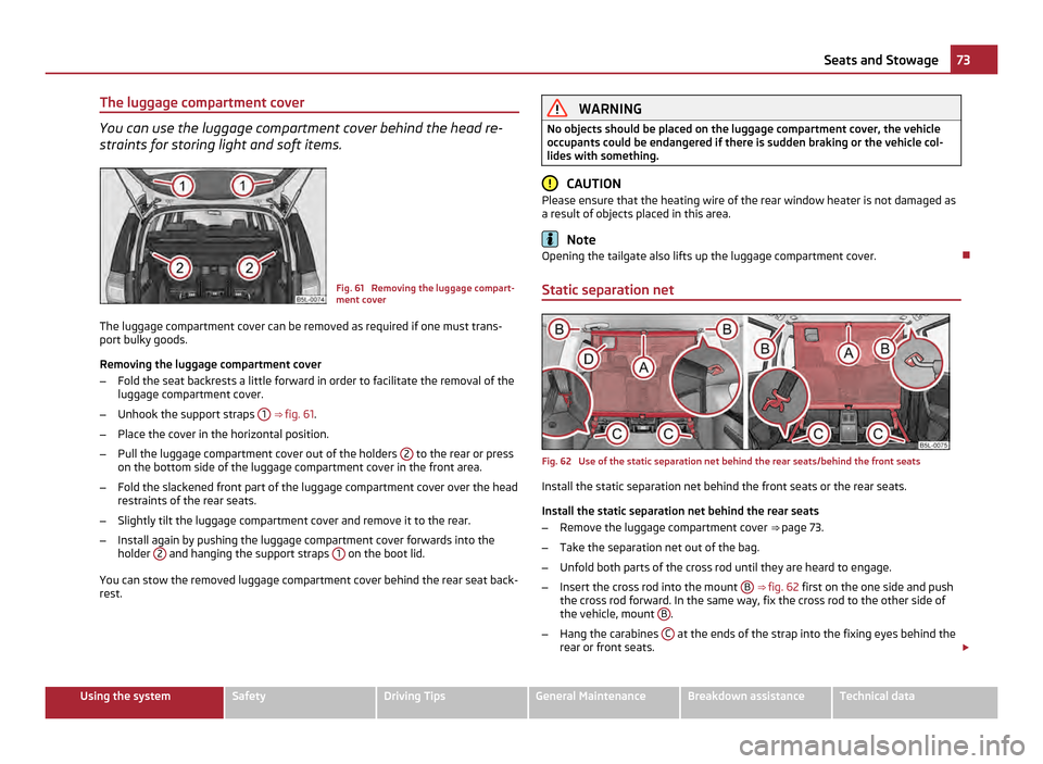
The luggage compartment cover
You can use the luggage compartment cover behind the head re-
straints for storing light and soft items.
Fig. 61 Removing the luggage compart-
ment cover
The luggage compartment cover can be removed as required if one must trans-
port bulky goods.
Removing the luggage compartment cover
– Fold the seat backrests a little forward in order to facilitate the removal of the
luggage compartment cover.
– Unhook the support straps 1
⇒ fig. 61 .
– Place the cover in the horizontal position.
– Pull the luggage compartment cover out of the holders 2 to the rear or press
on the bottom side of the luggage compartment cover in the front area.
– Fold the slackened front part of the luggage compartment cover over the head
restraints of the rear seats.
– Slightly tilt the luggage compartment cover and remove it to the rear.
– Install again by pushing the luggage compartment cover forwards into the
holder 2 and hanging the support straps
1 on the boot lid.
You can stow the removed luggage compartment cover behind the rear seat back-
rest. WARNING
No objects should be placed on the luggage compartment cover, the vehicle
occupants could be endangered if there is sudden braking or the vehicle col-
lides with something. CAUTION
Please ensure that the heating wire of the rear window heater is not damaged as
a result of objects placed in this area. Note
Opening the tailgate also lifts up the luggage compartment cover.
Static separation net Fig. 62 Use of the static separation net behind the rear seats/behind the front seats
Install the static separation net behind the front seats or the rear seats.
Install the static separation net behind the rear seats
–
Remove the luggage compartment cover ⇒ page 73.
– Take the separation net out of the bag.
– Unfold both parts of the cross rod until they are heard to engage.
– Insert the cross rod into the mount B
⇒ fig. 62 first on the one side and push
the cross rod forward. In the same way, fix the cross rod to the other side of
the vehicle, mount B .
– Hang the carabines C at the ends of the strap into the fixing eyes behind the
rear or front seats. £ 73
Seats and Stowage Using the system Safety Driving Tips General Maintenance Breakdown assistance Technical data
Page 90 of 252
Heating
Using the system The heating system delivers air into the interior of the vehicle and
warms it as required.
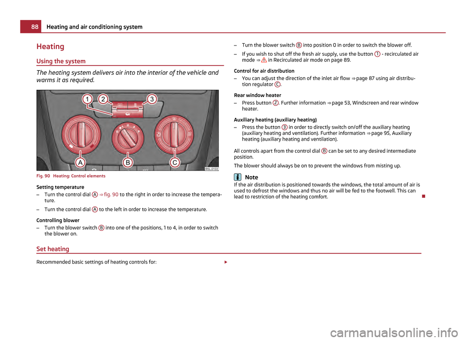
Fig. 90 Heating: Control elements
Setting temperature
–
Turn the control dial A
⇒ fig. 90 to the right in order to increase the tempera-
ture.
– Turn the control dial A to the left in order to increase the temperature.
Controlling blower
– Turn the blower switch B into one of the positions, 1 to 4, in order to switch
the blower on. –
Turn the blower switch B into position 0 in order to switch the blower off.
– If you wish to shut off the fresh air supply, use the button 1 - recirculated air
mode ⇒ in Recirculated air mode on page 89.
Control for air distribution
– You can adjust the direction of the inlet air flow ⇒
page 87 using air distribu-
tion regulator C .
Rear window heater
– Press button 2 . Further information
⇒ page 53, Windscreen and rear window
heater.
Auxiliary heating (auxiliary heating)
– Press the button 3 in order to directly switch on/off the auxiliary heating
(auxiliary heating and ventilation). Further information ⇒
page 95, Auxiliary
heating (auxiliary heating and ventilation).
All controls apart from the control dial B can be set to any desired intermediate
position.
The blower should always be on to prevent the windows from misting up. Note
If the air distribution is positioned towards the windows, the total amount of air is
used to defrost the windows and thus no air will be fed to the footwell. This can
lead to restriction of the heating comfort.
Set heating Recommended basic settings of heating controls for:
£88
Heating and air conditioning system
Page 92 of 252
The cooling only operates if button
AC ⇒
fig. 91 1 is pressed, and the following
conditions are met:
● engine running,
● outside temperature above approx. +2 °C and
● blower switch switched on (positions 1 to 4).
Air at a temperature of about 5 °C may flow out of the vents under certain circum-
stances when the cooling system is operating. Lengthy and uneven distribution of
the air flow out of the vents and large differences in temperature, for example
when getting out of the vehicle, can result in chills in sensitive persons. Note
● We recommend that you have the air conditioning system cleaned by a spe-
cialist garage once every year.
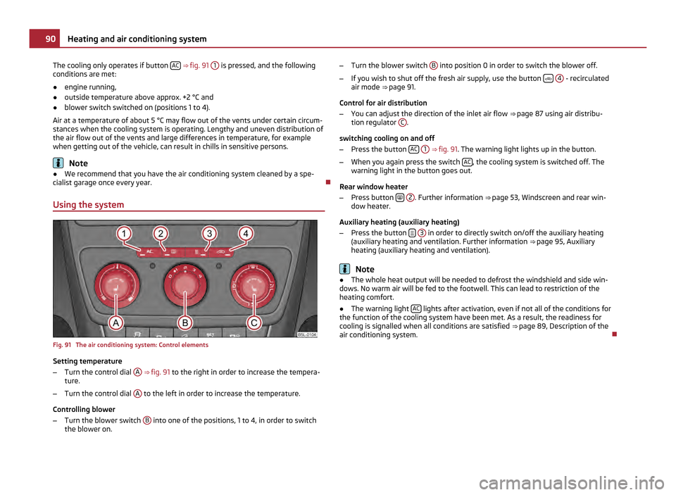
Using the system Fig. 91 The air conditioning system: Control elements
Setting temperature
–
Turn the control dial A
⇒
fig. 91 to the right in order to increase the tempera-
ture.
– Turn the control dial A to the left in order to increase the temperature.
Controlling blower
– Turn the blower switch B into one of the positions, 1 to 4, in order to switch
the blower on. –
Turn the blower switch B into position 0 in order to switch the blower off.
– If you wish to shut off the fresh air supply, use the button
4 - recirculated
air mode ⇒
page 91.
Control for air distribution
– You can adjust the direction of the inlet air flow ⇒
page 87 using air distribu-
tion regulator C .
switching cooling on and off
– Press the button AC
1 ⇒
fig. 91 . The warning light lights up in the button.
– When you again press the switch AC , the cooling system is switched off. The
warning light in the button goes out.
Rear window heater
– Press button
2 . Further information
⇒
page 53, Windscreen and rear win-
dow heater.
Auxiliary heating (auxiliary heating)
– Press the button
3 in order to directly switch on/off the auxiliary heating
(auxiliary heating and ventilation. Further information ⇒ page 95
, Auxiliary
heating (auxiliary heating and ventilation). Note
● The whole heat output will be needed to defrost the windshield and side win-
dows. No warm air will be fed to the footwell. This can lead to restriction of the
heating comfort.
● The warning light AC lights after activation, even if not all of the conditions for
the function of the cooling system have been met. As a result, the readiness for
cooling is signalled when all conditions are satisfied ⇒
page 89, Description of the
air conditioning system. 90
Heating and air conditioning system
Page 94 of 252
WARNING
You should not leave recirculated air mode on over a longer period of time, as
“stale ” air may result in fatigue in the driver and occupants, divert your atten-
tion and also cause the windows to mist up. The risk of having an accident in-
creases. Switch recirculated air mode off as soon as the windows begin mist-
ing up.
Climatronic (automatic air conditioning) Description The Climatronic system is an automatic heating, fresh air and cool-
ing system which provides optimal comfort for the occupants of the
car.
The Climatronic maintains fully automatically a convenience temperature. This is
achieved by automatically varying the temperature of the out-flowing air, the
blower stages and the air distribution. The system also takes into account sun-
light which eliminates the need to alter the settings manually. The automatic
mode
⇒
page 93 ensures maximum well-being of the occupants at all times of
the year.
Description of Climatronic system
The cooling operates only if the following conditions are met:
● engine running,
● outside temperature above approx. +2 °C,
● AC switched on.
The AC compressor is switched off at a high coolant temperature in order to en-
sure cooling of the engine at high loads.
Recommended setting for all periods of the year:
● Set the desired temperature, we recommend 22 °C.
● Press the button AUTO
⇒ fig. 92 .
● Move the air outlet vents 3 and 4 ⇒
fig. 88 so that the air flow is directed
slightly upwards. Note
● We recommend that you have Climatronic cleaned by a specialist garage once
every year.
● On vehicles equipped with a factory-fitted radio or radio navigation system,
the information of the Climatronic is also shown on the display. This function can
be switched off, see operating instructions of the radio or the radio navigation
system.
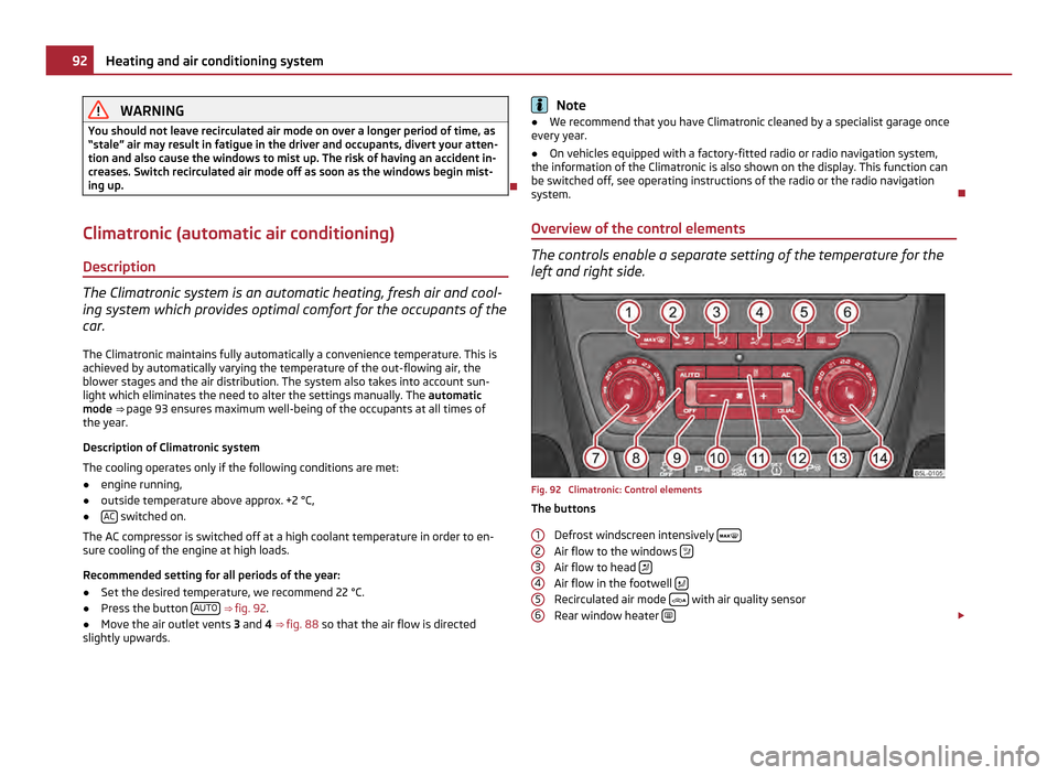
Overview of the control elements The controls enable a separate setting of the temperature for the
left and right side.
Fig. 92 Climatronic: Control elements
The buttons
Defrost windscreen intensively Air flow to the windows
Air flow to head
Air flow in the footwell
Recirculated air mode
with air quality sensor
Rear window heater £
1 2
3
4
5
692
Heating and air conditioning system
Page 95 of 252
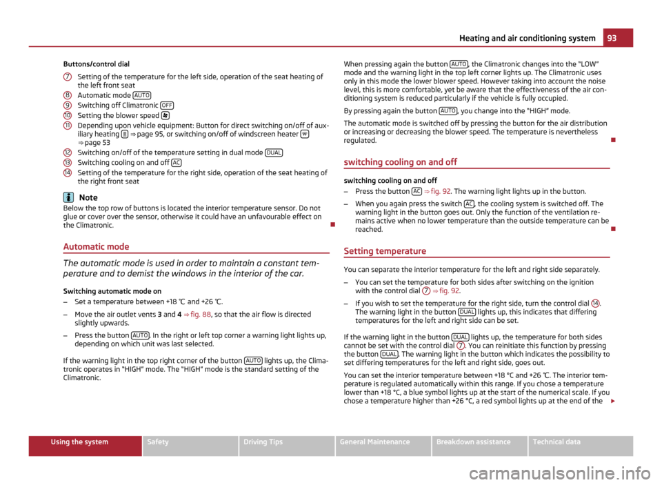
Buttons/control dial
Setting of the temperature for the left side, operation of the seat heating of
the left front seat
Automatic mode AUTOSwitching off Climatronic
OFFSetting the blower speed
Depending upon vehicle equipment: Button for direct switching on/off of aux-
iliary heating ⇒
page 95, or switching on/off of windscreen heater ⇒ page 53
Switching on/off of the temperature setting in dual mode
DUALSwitching cooling on and off
ACSetting of the temperature for the right side, operation of the seat heating of
the right front seat
Note
Below the top row of buttons is located the interior temperature sensor. Do not
glue or cover over the sensor, otherwise it could have an unfavourable effect on
the Climatronic.
Automatic mode The automatic mode is used in order to maintain a constant tem-
perature and to demist the windows in the interior of the car.
Switching automatic mode on
– Set a temperature between +18 ℃ and +26 ℃.
– Move the air outlet vents 3 and 4 ⇒
fig. 88 , so that the air flow is directed
slightly upwards.
– Press the button AUTO . In the right or left top corner a warning light lights up,
depending on which unit was last selected.
If the warning light in the top right corner of the button AUTO lights up, the Clima-
tronic operates in
“HIGH” mode. The “HIGH” mode is the standard setting of the
Climatronic. 7 8
9
10
11
12
13
14 When pressing again the button
AUTO , the Climatronic changes into the “LOW”
mode and the warning light in the top left corner lights up. The Climatronic uses
only in this mode the lower blower speed. However taking into account the noise
level, this is more comfortable, yet be aware that the effectiveness of the air con-
ditioning system is reduced particularly if the vehicle is fully occupied.
By pressing again the button AUTO , you change into the “HIGH” mode.
The automatic mode is switched off by pressing the button for the air distribution
or increasing or decreasing the blower speed. The temperature is nevertheless
regulated.
switching cooling on and off switching cooling on and off
–
Press the button AC
⇒
fig. 92 . The warning light lights up in the button.
– When you again press the switch AC , the cooling system is switched off. The
warning light in the button goes out. Only the function of the ventilation re-
mains active when no lower temperature than the outside temperature can be
reached.
Setting temperature You can separate the interior temperature for the left and right side separately.
–
You can set the temperature for both sides after switching on the ignition
with the control dial 7
⇒ fig. 92 .
– If you wish to set the temperature for the right side, turn the control dial 14 .
The warning light in the button DUAL lights up, this indicates that differing
temperatures for the left and right side can be set.
If the warning light in the button DUAL lights up, the temperature for both sides
cannot be set with the control dial 7 . You can reinitiate this function by pressing
the button DUAL . The warning light in the button which indicates the possibility to
set differing temperatures for the left and right side, goes out.
You can set the interior temperature between +18 °C and +26 ℃. The interior tem-
perature is regulated automatically within this range. If you chose a temperature
lower than +18 °C, a blue symbol lights up at the start of the numerical scale. If you
chose a temperature higher than +26 °C, a red symbol lights up at the end of the £ 93
Heating and air conditioning system Using the system Safety Driving Tips General Maintenance Breakdown assistance Technical data
Page 97 of 252
Defrosting windscreen
Defrosting windscreen - switching on
–
Press the button ⇒ fig. 92
.
– Press the button ⇒
fig. 92 .
Defrosting windscreen - switching off
– Once again press the button or the button
AUTO .
– Once again press the button .
The temperature control is controlled automatically. More air flows out of the air
outlet vents 1 and 2.
Auxiliary heating (auxiliary heating and ventilation)
Description and important information The auxiliary heating (auxiliary heating and ventilation) heats or
supplies the interior of the vehicle with fresh air independent of the
engine.
Auxiliary heating (auxiliary heating)
The auxiliary heater (parking heater) functions in connection with the air-condi-
tioning system or Climatronic.
It can be used when stationary, when engine is switched off for preheating of the
vehicle as well as while driving (e.g. during the heating phase of the engine).
The engine is also preheated when the vehicle is stationary and the engine is
switched off, if the auxiliary heating is switched on.
The auxiliary heating (auxiliary heating) warms up the coolant during the combus-
tion of fuel from the vehicle tank. The coolant warms up the air, which (if the
blower speed is not set to zero) flows into the occupant compartment.
Auxiliary ventilation
The auxiliary ventilation enables fresh air to flow into the vehicle interior by
switching off the engine, whereby the interior temperature is effectively de-
creased (e.g. with the vehicle parked in the sun). WARNING
● The auxiliary heating must never be operated in closed rooms - risk of poi-
soning!
● The auxiliary heating must not be running during refuelling - risk of fire.
● The exhaust pipe of the auxiliary heating is located on the underside of
the vehicle. Therefore do not place the vehicle, if you wish to operate the aux-
iliary heating, in such a way that the exhaust gases of the auxiliary heating
can come easily into contact with inflammable materials (e.g. dry grass) or
easily inflammable substances (e.g. fuel run out). Note
If the auxiliary heating runs, the fuel consumption comes from the vehicle tank.
The auxiliary heating automatically controls the filling level in the fuel tank. If only
a low quantity of fuel is present in the fuel tank, the function of the auxiliary heat-
ing is blocked.
● The exhaust pipe of the auxiliary heating, which is located on the underside of
the vehicle, must not be clogged and the exhaust flow must not be blocked.
● If the auxiliary heating and ventilation is running, the vehicle battery discharg-
es. If the auxiliary heating and ventilation has been operated several times over a
longer period, the vehicle must be driven a few kilometres in order to recharge the
vehicle battery.
● The auxiliary heating only switches the blower on, if it has achieved a coolant
temperature of approx. 50
°C.
● At low outside temperatures, this can result in a formation of water vapour in
the area of the engine compartment. This is quite normal and is not an operating
problem.
● After switching off the auxiliary heating, the coolant pump runs for a short pe-
riod.
● The auxiliary heating and ventilation does not switch on or comes on, if the
vehicle battery indicates a low loading state.
● The auxiliary heating (auxiliary heating) does not switch on, if the following
was shown in the information display or before switching off the ignition: Please
refuel! £ 95
Heating and air conditioning system Using the system Safety Driving Tips General Maintenance Breakdown assistance Technical data