ignition SKODA YETI 2013 1.G / 5L User Guide
[x] Cancel search | Manufacturer: SKODA, Model Year: 2013, Model line: YETI, Model: SKODA YETI 2013 1.G / 5LPages: 266, PDF Size: 26.71 MB
Page 27 of 266
Button/di-al
» Fig. 7
ActionOperation
DTurn upwards or down- wardsSelect dataTurn upwards or down-wardsSet data valuesPress brieflyShow dataPress brieflyConfirm data
Ice warning
First read and observe the introductory information and safety warn-ings
on page 23.
Prompt in the MAXI DOT display
If the outside temperature while driving drops to below +4°C, the following icon
appears on the display in front of the temperature display
. An audible signal is
emitted.
If the outside temperature is already below +4°C when turning the ignition on,
the
icon appears immediately. An audible signal is emitted.
Prompt in the segment display
If the outside temperature while driving drops to below +4°C, the temperature
display will show up with the following icon before this occurs
. An audible sig-
nal is emitted.
If the outside temperature is already below +4°C when turning the ignition on, the temperature display and the
icon appear immediately. An audible signal is
emitted.
After pressing Button
A
» Fig. 7 on page 23, the most recently displayed data is
shown.
WARNINGEven at temperatures around +4 °C, black ice may still be on the road surface!
Do not only rely upon the information given on the outside temperature dis-
play that there is no ice on the road.
Gear recommendation
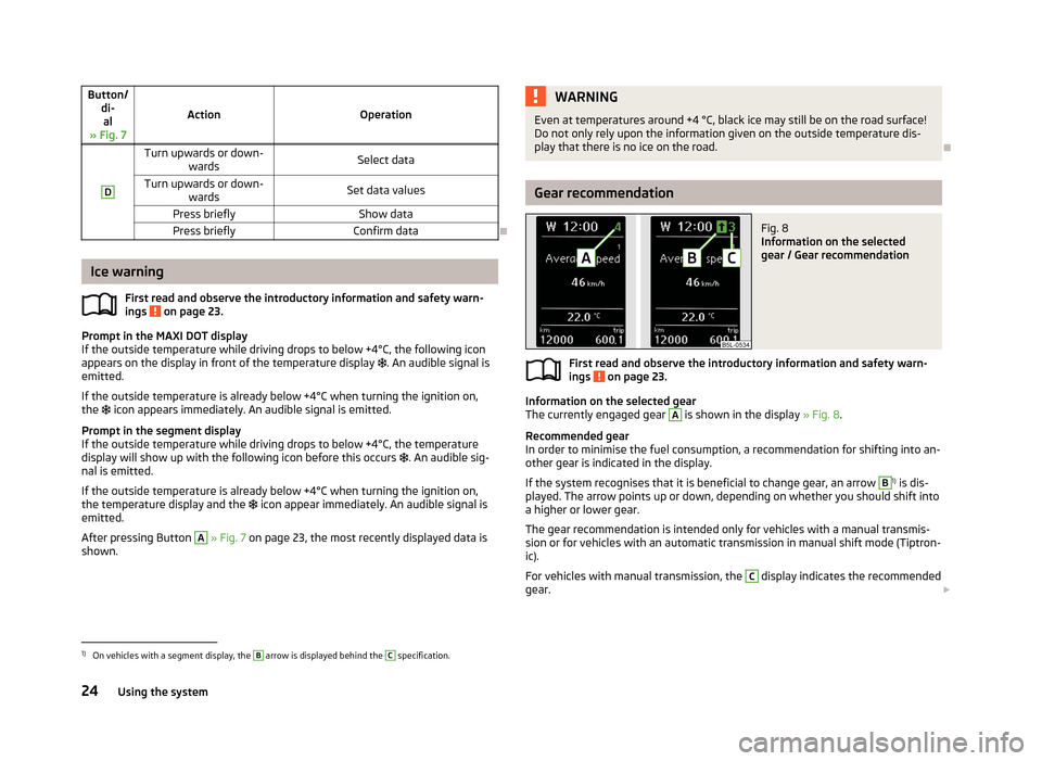
Fig. 8
Information on the selected
gear / Gear recommendation
First read and observe the introductory information and safety warn-
ings on page 23.
Information on the selected gear
The currently engaged gear
A
is shown in the display » Fig. 8.
Recommended gear
In order to minimise the fuel consumption, a recommendation for shifting into an-
other gear is indicated in the display.
If the system recognises that it is beneficial to change gear, an arrow
B
1) is dis-
played. The arrow points up or down, depending on whether you should shift into
a higher or lower gear.
The gear recommendation is intended only for vehicles with a manual transmis-
sion or for vehicles with an automatic transmission in manual shift mode (Tiptron-
ic).
For vehicles with manual transmission, the
C
display indicates the recommended
gear.
1)
On vehicles with a segment display, the
B
arrow is displayed behind the
C
specification.
24Using the system
Page 28 of 266
WARNINGThe driver is always responsible for selecting the correct gear in different driv-
ing situations, such as overtaking.
For the sake of the environment
Correct shifting up has the following advantages.■It helps to reduce fuel consumption.■
It reduces the operating noise.
■
It protects the environment.
■
It benefits the durability and reliability of the engine.
Door, boot or engine compartment warning
First read and observe the introductory information and safety warn-ings
on page 23.
Vehicles with a MAXI DOT display
If at least one door, the boot or bonnet is open, the display indicates the relevant
open door, boot or bonnet vehicle icon.
Vehicles with a segment display
If at least one door or the tailgate is open, the
warning light in the instrument
cluster lights up » page 16.
If at least one door or the tailgate is open, the
warning light in the instrument
cluster lights up » page 17.
An acoustic signal will also sound if you drive the vehicle above 6 km/h when a
door is open.
Compass point display
First read and observe the introductory information and safety warn-
ings
on page 23.
For vehicles with a factory fitted navigation system, an abbreviation for each
point of the compass (depending on the current direction of travel) is shown on
the top left-hand corner of the 1)
display.
The compass point display only operates when the ignition is switched on.
Multifunction display (MFD)
Introduction
This chapter contains information on the following subjects:
Memory
26
Information overview
26
Warning at excessive speeds
28
The driving data is displayed on the multifunction display. The multifunction display only operates if the ignition is switched on. After the ig-nition is switched on, the function that was last selected before switching off the
ignition is displayed.
For vehicles with a MAXI DOT display, the menu item MFD must be selected and
confirmed in the main menu » page 28, MAXI DOT display .
On vehicles with a MAXI DOT display, there is an option to fade out some of the information » page 29, Settings .
WARNING■
Concentrate fully at all times on your driving! As the driver you are fully re-
sponsible for the operation of your vehicle.■
Even at temperatures around +4 °C, black ice may still be on the road sur-
face! Do not only rely upon the information given on the outside temperature
display that there is no ice on the road.
1)
Applies to vehicles using the MAXI DOT display.
25Information system
Page 29 of 266
CAUTIONPull out the ignition key if coming in contact with the display (e.g. when cleaning)
to prevent any possible damage.
Note
■ In certain national versions the displays appear in the Imperial system of meas-
ures.■
If the display of the second speed is activated in mph, the current speed is not
indicated in km/h on the display.
■
The amount of fuel consumed will not be indicated.
Memory
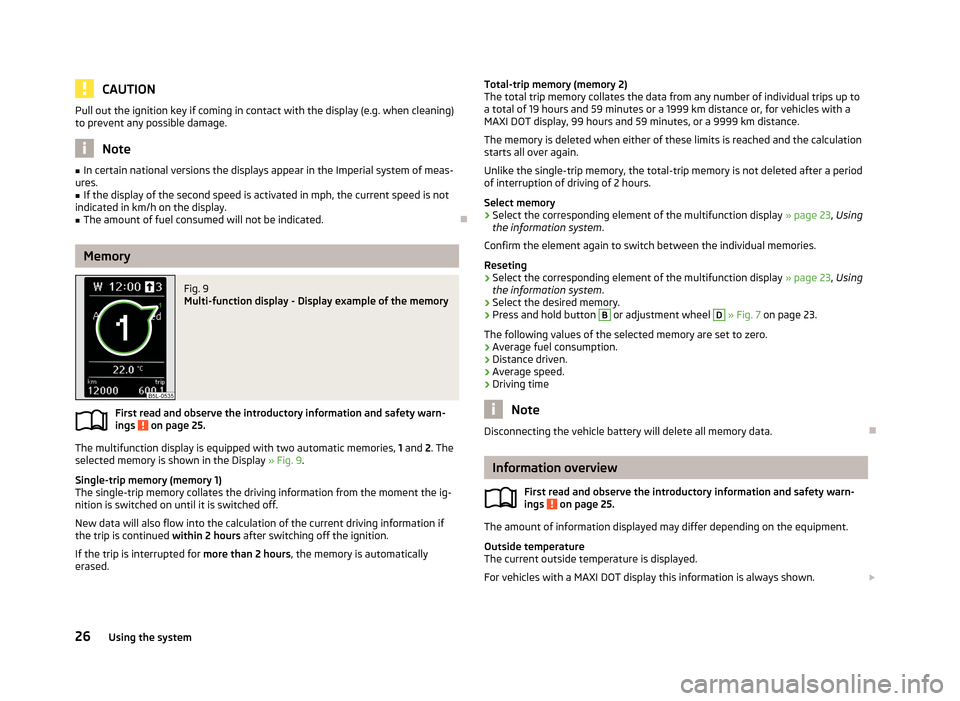
Fig. 9
Multi-function display - Display example of the memory
First read and observe the introductory information and safety warn-
ings on page 25.
The multifunction display is equipped with two automatic memories, 1 and 2. The
selected memory is shown in the Display » Fig. 9.
Single-trip memory (memory 1)
The single-trip memory collates the driving information from the moment the ig- nition is switched on until it is switched off.
New data will also flow into the calculation of the current driving information if
the trip is continued within 2 hours after switching off the ignition.
If the trip is interrupted for more than 2 hours, the memory is automatically
erased.
Total-trip memory (memory 2)
The total trip memory collates the data from any number of individual trips up to
a total of 19 hours and 59 minutes or a 1999 km distance or, for vehicles with a
MAXI DOT display, 99 hours and 59 minutes, or a 9999 km distance.
The memory is deleted when either of these limits is reached and the calculation
starts all over again.
Unlike the single-trip memory, the total-trip memory is not deleted after a period of interruption of driving of 2 hours.
Select memory›
Select the corresponding element of the multifunction display » page 23, Using
the information system .
Confirm the element again to switch between the individual memories.
Reseting
›
Select the corresponding element of the multifunction display » page 23, Using
the information system .
›
Select the desired memory.
›
Press and hold button
B
or adjustment wheel
D
» Fig. 7 on page 23.
The following values of the selected memory are set to zero. › Average fuel consumption.
› Distance driven.
› Average speed.
› Driving time
Note
Disconnecting the vehicle battery will delete all memory data.
Information overview
First read and observe the introductory information and safety warn-
ings
on page 25.
The amount of information displayed may differ depending on the equipment.
Outside temperature
The current outside temperature is displayed.
For vehicles with a MAXI DOT display this information is always shown.
26Using the system
Page 31 of 266
Warning at excessive speedsFirst read and observe the introductory information and safety warn-
ings
on page 25.
Adjust the speed limit while the vehicle is stationary
›
Select the menu item Speed warning (MAXI DOT display) or (segment dis-
play).
›
Activate the speed limit option by confirming this menu item 1)
.
›
Set the desired speed limit, e.g. 50 km/h.
›
Store the speed limit by confirming the set value, or wait several seconds; your
settings will be saved automatically.
The speed limit can be adjusted from 30 km/h to 250 km/h in 5 km/h increments.
Adjusting the speed limit while the vehicle is moving
›
Select the menu item Speed warning (MAXI DOT display) or
(segment dis-
play).
›
Drive at the desired speed, e.g. 50 km/h.
›
Confirm the current speed as the speed limit.
If you wish to adjust the set speed limit, you can do so in 5 km/h intervals (e.g. the
accepted speed of 47 km/h increases to 50 km/h or decreases to 45 km/h).
›
Store the speed limit, or wait several seconds; your settings will be saved auto-
matically.
Change or disable speed limit
›
Select the menu item Speed warning (MAXI DOT display) or
(segment dis-
play).
›
By confirming the stored value, the speed limit is disabled.
›
By reconfirming, the option to change the speed limit is activated.
If the set speed limit is exceeded, an audible signal will sound as a warning. The menu item Speed warning (MAXI DOT display) or
(Segment display) appears in
the display at the same time as the set threshold.
The set speed limit value remains stored even after switching off the ignition.
MAXI DOT display
Introduction
This chapter contains information on the following subjects:
Main menu
28
Settings
29
The MAXI DOT display provides you with information about the current operating
state of your vehicle. Depending on the vehicle equipment, it also provides you
with data relating to the radio, multifunction display (MFD), mobile phone, naviga-
tion system, automatic gearbox and devices connected via the MDI input. Further- more, it allows the adjustment of some other features of your vehicle.
WARNINGConcentrate fully at all times on your driving! As the driver you are fully re-
sponsible for the operation of your vehicle.
CAUTION
Pull out the ignition key if coming in contact with the display (e.g. when cleaning)
to prevent any possible damage.
Main menu
First read and observe the introductory information and safety warn-
ings
on page 28.
In order to activate the primary menu MAIN MENU, press and hold down Button
A
or
C
» Fig. 7 on page 23 . By briefly pressing the
C
button you will reach one
level higher.
1)
If no value is set the output value 30 km/h is automatically displayed.
28Using the system
Page 33 of 266

Coming HomeSwitch on/off and adjust the light duration of the Com-
ing Home function. Further information » page 51,
COMING HOME / LEAVING HOME .Leaving HomeSwitch on/off and adjust the light duration of the Com-
ing Home function. Further information » page 51,
COMING HOME / LEAVING HOME .Dayl. dri. lightEnable / disable the daytime running lights. Further in-
formation » page 48, Daylight running lights (DAY
LIGHT) .Rear wiperSwitch on/off the function for automatic rear window
wiping. Further information » page 57, Automatic rear
window wiping .Lane ch. flashSwitch on/off the convenience flashing function. Fur-
ther information » page 49, “Convenience turn sig-
nal” .Travel modeSwitch on/off the travel model function. Further infor-
mation » page 50 , Tourist lights (Travel mode) .Factory settingRestore the factory setting for the lighting.
Time
The time, time format (12 or 24 hour indicator) and the changeover between sum-
mer/winter time can be set here.
Winter tyres
Here, the speed and the switching on and off of the acoustic signals when ex-
ceeding this speed can be adjusted. This function is, for example, used for winter
tyres where the maximum permissible speed is lower than the maximum speed ofthe vehicle » page 212, Tyres and wheel rims .
As soon as the parking procedure is completed, an audible signal sounds and the
following message appears in the information display.
Winter tyres: max. speed … km/h.
Units
The units for the temperature, consumption and distance driven can be set here.
Assistants
The tones of the audible signals for the parking aid can be adjusted here.
Further information » page 140, Parking aid .
Alt. speed dis.
Here, the display of the second speed in mph 1)
can be activated.
Further information » page 13, Display of the second speed .
Service
The days and kilometres remaining until the next service can be displayed here.
Further information » page 30, Service interval display .
Factory setting
The factory setting of the functions of the MAXI DOT display can be restored here.
Service interval display
Introduction
This chapter contains information on the following subjects:
Prompt in the segment display
31
Prompt in the MAXI DOT display
31
Before the next service interval is reached, a message concerning the kilometres
and days remaining until the next service is due is shown for about 10 seconds
after the ignition is switched on.
This information can also be displayed manually with the ignition at all times.
The kilometre indicator or the days indicator reduces in steps of 100 km or, where
applicable, days until the service due date is reached.
Note
■ Information is retained in the Service Interval Display even after the vehicle bat-
tery is disconnected.■
If the instrument cluster is exchanged after a repair, the correct values must be
entered in the counter for the Service Interval Display. This work is carried out by a specialist garage.
■
In some national versions the displays appear in the Imperial system of meas-
urement.
■
For more information on the service intervals, see » page 182, Service intervals .
1)
For models with the speedometer in mph, the second speed is displayed in km/h.
30Using the system
Page 34 of 266
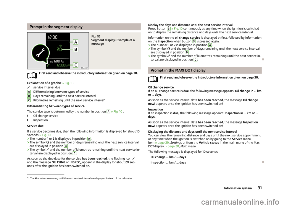
Prompt in the segment displayFig. 10
Segment display: Example of a
message
First read and observe the introductory information given on page 30.
Explanation of a graphic » Fig. 10 .
service interval due
Differentiating between types of service
Days remaining until the next service interval
Kilometres remaining until the next service interval 1)
Differentiating between types of service
The service type is determined by the number in position
A
» Fig. 10 .
Oil change service
Inspection
Service due
If a service becomes due, then the following information is displayed for about 10
seconds » Fig. 10.
› The number
1 or 2 is displayed in position
A
.
› The symbol
and the number of days remaining until the next service interval
are displayed in position
B
.
› The symbol
and the number of kilometres remaining until the next service in-
terval are displayed in position
C
.
As soon as the due date for the service has been reached, the flashing icon
and the message OIL CHNG or INSPEC_ appear in the display for about 20 sec-
onds after the ignition has been switched on.
ABCDisplay the days and distance until the next service interval
Press Button 3 » Fig. 10 continuously at any time when the ignition is switched
on to display the remaining distance and days until the next service interval.
Information on the oil change service is displayed at first, followed by information
on the inspection when button 3
is pressed again.
› The number
1 or 2 is displayed in position
A
.
› The symbol
and the number of days remaining until the next service interval
are displayed in position
B
.
› The symbol
and the number of kilometres remaining until the next service in-
terval are displayed in position
C
.
Prompt in the MAXI DOT display
First read and observe the introductory information given on page 30.
Oil change service
If an oil change service is due, the following message appears: Oil change in … km
or … days.
As soon as the service interval date has been reached, the message Oil change
now! appears once the ignition has been switched on!
Inspection
If an inspection is due, the following message appears: Inspection in ... km or ...
days.
As soon as the service interval date has been reached, the message Inspection
now! appears once the ignition has been switched on!
Displaying the distance and days until the next service interval You can view the remaining distance and days until the next service appointmentat any time when the ignition is switched on by going to the Service menu
item » page 29 , Settings or from the Vehicle status in the main menu of the Maxi
DOTdisplay. » page 28, Main menu .
The following message is displayed for 10 seconds. Oil change ... km / ... days
Inspection ... km / ... days
1)
The kilometres remaining until the next service interval are displayed instead of the odometer.
31Information system
Page 36 of 266
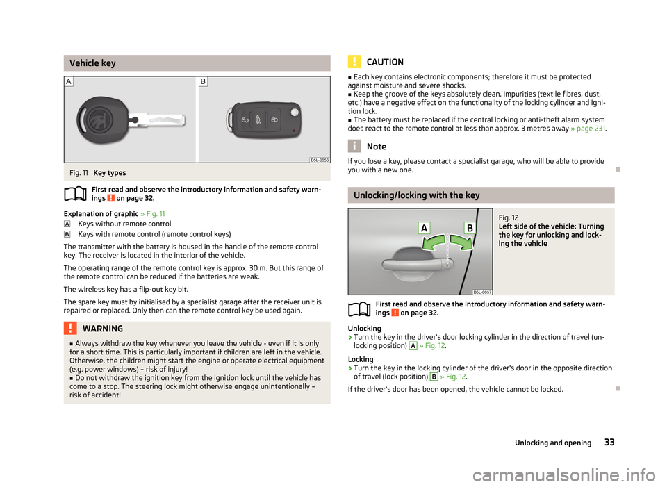
Vehicle keyFig. 11
Key types
First read and observe the introductory information and safety warn- ings
on page 32.
Explanation of graphic » Fig. 11
Keys without remote control
Keys with remote control (remote control keys)
The transmitter with the battery is housed in the handle of the remote control key. The receiver is located in the interior of the vehicle.
The operating range of the remote control key is approx. 30 m. But this range ofthe remote control can be reduced if the batteries are weak.
The wireless key has a flip-out key bit.The spare key must by initialised by a specialist garage after the receiver unit is
repaired or replaced. Only then can the remote control key be used again.
WARNING■ Always withdraw the key whenever you leave the vehicle - even if it is only
for a short time. This is particularly important if children are left in the vehicle.
Otherwise, the children might start the engine or operate electrical equipment
(e.g. power windows) – risk of injury!■
Do not withdraw the ignition key from the ignition lock until the vehicle has
come to a stop. The steering lock might otherwise engage unintentionally – risk of accident!
CAUTION■ Each key contains electronic components; therefore it must be protected
against moisture and severe shocks.■
Keep the groove of the keys absolutely clean. Impurities (textile fibres, dust,
etc.) have a negative effect on the functionality of the locking cylinder and igni-
tion lock.
■
The battery must be replaced if the central locking or anti-theft alarm system
does react to the remote control at less than approx. 3 metres away » page 231.
Note
If you lose a key, please contact a specialist garage, who will be able to provide
you with a new one.
Unlocking/locking with the key
Fig. 12
Left side of the vehicle: Turning
the key for unlocking and lock-
ing the vehicle
First read and observe the introductory information and safety warn-
ings on page 32.
Unlocking
›
Turn the key in the driver's door locking cylinder in the direction of travel (un- locking position)
A
» Fig. 12 .
Locking
›
Turn the key in the locking cylinder of the driver's door in the opposite direction
of travel (lock position)
B
» Fig. 12 .
If the driver's door has been opened, the vehicle cannot be locked.
33Unlocking and opening
Page 38 of 266
Unlocking/locking – KESSYFig. 14
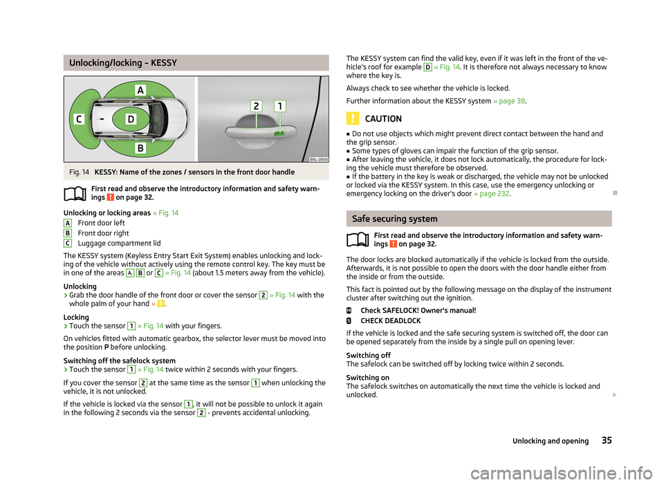
KESSY: Name of the zones / sensors in the front door handle
First read and observe the introductory information and safety warn- ings
on page 32.
Unlocking or locking areas » Fig. 14
Front door left
Front door right
Luggage compartment lid
The KESSY system (Keyless Entry Start Exit System) enables unlocking and lock-
ing of the vehicle without actively using the remote control key. The key must be
in one of the areas
A,
B
or
C
» Fig. 14 (about 1.5 meters away from the vehicle).
Unlocking
›
Grab the door handle of the front door or cover the sensor
2
» Fig. 14 with the
whole palm of your hand » .
Locking
›
Touch the sensor
1
» Fig. 14 with your fingers.
On vehicles fitted with automatic gearbox, the selector lever must be moved into the position P before unlocking.
Switching off the safelock system
›
Touch the sensor
1
» Fig. 14 twice within 2 seconds with your fingers.
If you cover the sensor
2
at the same time as the sensor
1
when unlocking the
vehicle, it is not unlocked.
If the vehicle is locked via the sensor
1
, it will not be possible to unlock it again
in the following 2 seconds via the sensor
2
- prevents accidental unlocking.
ABCThe KESSY system can find the valid key, even if it was left in the front of the ve-
hicle's roof for example D » Fig. 14 . It is therefore not always necessary to know
where the key is.
Always check to see whether the vehicle is locked. Further information about the KESSY system » page 38.
CAUTION
■
Do not use objects which might prevent direct contact between the hand and
the grip sensor.■
Some types of gloves can impair the function of the grip sensor.
■
After leaving the vehicle, it does not lock automatically, the procedure for lock-
ing the vehicle must therefore be observed.
■
If the battery in the key is weak or discharged, the vehicle may not be unlocked
or locked via the KESSY system. In this case, use the emergency unlocking or
emergency locking on the driver's door » page 232.
Safe securing system
First read and observe the introductory information and safety warn-
ings
on page 32.
The door locks are blocked automatically if the vehicle is locked from the outside.
Afterwards, it is not possible to open the doors with the door handle either from
the inside or from the outside.
This fact is pointed out by the following message on the display of the instrument
cluster after switching out the ignition.
Check SAFELOCK! Owner's manual!
CHECK DEADLOCK
If the vehicle is locked and the safe securing system is switched off, the door can
be opened separately from the inside by a single pull on opening lever.
Switching off
The safelock can be switched off by locking twice within 2 seconds.
Switching on
The safelock switches on automatically the next time the vehicle is locked and unlocked.
35Unlocking and opening
Page 39 of 266
Switch-on display
The indicator light flashes for around 2 seconds in quick succession, afterwards it
begins to flash evenly at longer intervals.
Switch-off display
The indicator light in the driver door flashes for about 2 seconds fast, goes out
and starts to flash at longer intervals after about 30 seconds.WARNINGIf the car is locked and the safe securing system activated, no people must re-
main in the car as it will then not be possible to either unlock a door or open a
window from the inside. The locked doors make it more difficult for rescuers
to get into the vehicle in an emergency – risk to life!
Note
This function only applies to certain countries.
Individual settings
First read and observe the introductory information and safety warn-
ings
on page 32.
The following central locking functions can be set via the MAXI DOT dis-
play » page 29 , Settings .
Opening a single door
This function makes it possible to only unlock the driver's door. The other doors,
the fuel filler flap and the boot lid remain locked and are only unlocked after be- ing opened again.
Unlocking a vehicle side door
This function enables you to unlock both doors on the driver's side. The other doors, the fuel filler flap and the boot lid remain locked and are only unlocked af-
ter being opened again.
Unlocking the vehicle with the KESSY system
This function enables you to unlock all the doors, individual doors, both doors on the left or right vehicle side. The other doors, the fuel filler flap and the boot lid
remain locked and are only unlocked after being opened again.
Automatic locking/unlocking
All doors are locked from a speed of around 15 km/h. The button in the handle of
the boot lid is deactivated.
If the ignition key is withdrawn, the car is then automatically unlocked again. In
addition, it is possible for the driver or front passenger to unlock the car by press- ing the central locking button .
The vehicle doors can be unlocked and opened at any time by pulling once on the door opening lever.WARNINGLocked doors prevent unwanted entry into the vehicle from outside, for exam-ple at road crossings.
Locking/unlocking the vehicle from the inside
Fig. 15
Central locking button
First read and observe the introductory information and safety warn-ings on page 32.
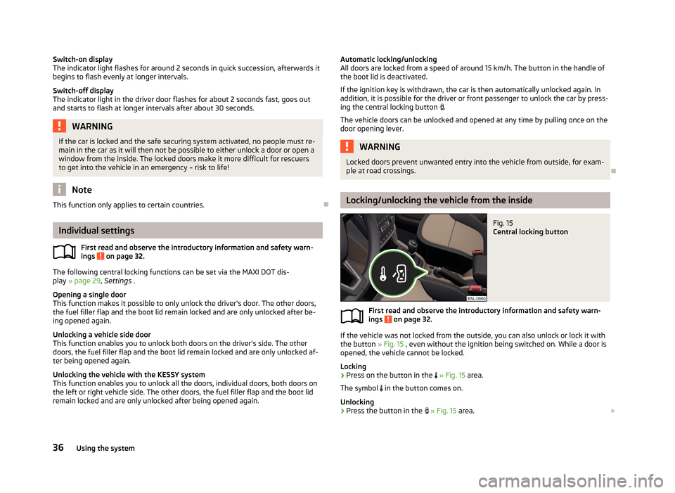
If the vehicle was not locked from the outside, you can also unlock or lock it with
the button » Fig. 15 , even without the ignition being switched on. While a door is
opened, the vehicle cannot be locked.
Locking
›
Press on the button in the
» Fig. 15 area.
The symbol
in the button comes on.
Unlocking
›
Press the button in the
» Fig. 15 area.
36Using the system
Page 42 of 266
Activation after 90 hours›Unlock the vehicle using the symbol button on the remote control key.›
Unlocking the driver's door in an emergency » page 232.
Anti-theft alarm system
Introduction
This chapter contains information on the following subjects:
Activating/deactivating
39
Interior monitor and towing protection
40
The anti-theft alarm system (hereinafter referred to only as alarm system) increa-
ses protection against break-in attempts into the vehicle.
The alarm system triggers audible and visual signals if an attempt is made to
break into the vehicle (hereafter referred to only as alarm).
An alarm is triggered when the following monitored areas of the vehicle have a
fault.
› Bonnet.
› Boot lid.
› Doors.
› Ignition lock.
› Vehicle inclination
» page 40, Interior monitor and towing protection .
› Interior of car
» page 40, Interior monitor and towing protection .
› A drop in voltage of the on-board power supply.
› Socket of the factory-fitted towing device
» page 157, Driving with a trailer .
An alarm is immediately triggered if either of the two battery terminals is discon-
nected while the anti-theft alarm system is activated.
The alarm is switched off by unlocking the vehicle or switching on the ignition.
CAUTION
Before leaving the vehicle, it must be checked that all of the windows, doors and
the sliding/tilting roof are locked in order to ensure the full functionality of the
anti-theft alarm system.
Note
The working life of the alarm siren is 5 years.
Activating/deactivating
First read and observe the introductory information and safety warn-ings
on page 39.
Activating
The anti-theft alarm system is activated automatically approximately 30 seconds
after the vehicle is locked.
If you unlock the vehicle and do not open a door or the boot lid within the next
30 seconds, the vehicle will lock again automatically and the safelock system or
anti-theft alarm system will be switched on. This function is intended to prevent
the car being unlocked unintentionally.
Deactivating
The anti-theft alarm system is deactivated automatically after the vehicle is un-
locked. If the vehicle is not opened within 30 seconds, the anti-theft alarm sys-
tem is automatically activated again.
The alarm system is also deactivated if you unlock the driver door using the key
within 45 seconds of locking the vehicle.
Note
■ When the Vehicle is unlocked using the key on the driver's door, insert the key
into the ignition and switch on the ignition in order to deactivate the alarm sys-
tem.■
You can switch the audible signalling of the activation of the warning system on
and off in the Maxi DOT display in the menu item ATA confirm » page 29 .
39Unlocking and opening