warning light SKODA YETI 2014 1.G / 5L Repair Manual
[x] Cancel search | Manufacturer: SKODA, Model Year: 2014, Model line: YETI, Model: SKODA YETI 2014 1.G / 5LPages: 248, PDF Size: 29.49 MB
Page 142 of 248
N - Neutral
The power transmission to the drive wheels is interrupted in this mode.D
- Mode for forwards travel (normal programme)
In mode D, the forward gears are automatically changed according to the en-
gine load, accelerator pedal actuation and driving speed.
S
- Mode for forwards travel (sports programme)
In mode S , the forward gears are shifted automatically up and down at high-
er engine speeds than in mode D.
Before changing to mode S from mode D, press the lock button in the direction
of arrow
1
» Fig. 130 .
Fault in the automatic gearbox
A fault in the automatic gearbox can, for example, be noticeable by the follow-
ing.
› Only certain gears are selected.
› The reverse gear
R cannot be used.
› Shifting gears in Tiptronic mode is not possible.
CAUTION
If an error occurs on the automatic transmission the help of a specialist firm
should be sought immediately - there is a risk of damaging the vehicle.
Selector lever lock
Read and observe
and on page 138 first.
The selector lever is locked in mode P and N to prevent that the forward driv-
ing is selected accidentally, thereby setting the vehicle in motion.
The selector lever is locked only when the vehicle is stationary and at speeds
up to 5 km/h.
The selector lever lock is indicated by the illumination of the warning light .
The selector lever is not locked when quickly moving across the position N
(e.g. from R to D). This, for example, helps to rock out a vehicle that is stuck,
e.g. in a bank of snow. The selector lever lock will engage if the lever is in posi-
tion N for more than approx. 2 seconds without the brake pedal being de-
pressed.
Releasing selector lever from mode P or N (selector lever lock)
›
Press the brake pedal and the lock button at the same time in the direction
of
1
» Fig. 130 on page 138 .
Just depress the brake pedal, if you would like to change from the mode N to
D .
Defective selector lever lock If the selector lever lock is defective or its power supply is interrupted (e.g. dis-
charged vehicle battery, faulty fuse), the selector lever can no longer be moved
out of position P in the normal manner and the vehicle can no longer be driven.
The selector lever must be unlocked specially » page 212.
Note
If you want to move the selector lever from mode P to mode D or vice versa,
move the selector lever quickly. This prevents that you accidentally select
mode R or N.
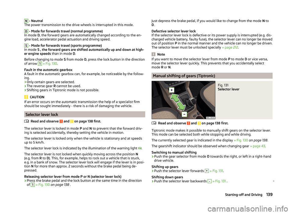
Manual shifting of gears (Tiptronic)
Fig. 131
Selector lever
Read and observe and on page 138 first.
Tiptronic mode makes it possible to manually shift gears on the selector lever.
This mode can be selected both while stopping and while driving.
The currently selected gear is indicated in the display » Fig. 130 on page 138 .
The gearshift indicator should be observed when changing gear » page 43.
Switching to manual shifting
›
Push the gear selector from mode D towards the right, or left in a right-hand
drive vehicle.
Shifting up gears
›
Push the selector lever forwards
+
» Fig. 131 .
Shifting down gears
›
Push the selector lever backwards
-
» Fig. 131 .
139Starting-off and Driving
Page 145 of 248
Driving off paved roadsRead and observe
on page 141 first.
Only drive on such roads and in such terrain, which match the vehicle parame-ters » page 222 , Technical data as well as your driving skills.
The driver is always responsible for deciding whether the vehicle can handle
travelling in the given terrain.
When travelling off paved roads, we recommend activating the OFF ROAD
mode » page 144 .
WARNINGDrive particularly aware and pro-actively outside paved roads.■Always adjust your driving to the current terrain and weather conditions.
Excessive speed or incorrect driving manoeuvres can cause damage to the
vehicle and lead to serious injuries.■
Objects trapped under the floor of the vehicle can damage the fuel lines,
the brake system, the seals and other parts of the chassis. Check the un-
derside of the vehicle and remove the trapped objects.
■
Combustible objects such as dry leaves or twigs caught under the base of
the vehicle could ignite on hot vehicle parts - risk of fire!
CAUTION
■ Pay attention to the ground clearance of the vehicle! When driving over ob-
jects which are larger than the ground clearance, the chassis and its compo-
nents can get damaged.■
Drive slowly in unknown terrain and watch out for unexpected obstacles,
such as potholes, rocks, stumps, etc.
■
Check up on confusing sections of unpaved roads before travelling on them
and consider whether such travelling is possible without risk.
Assist systems
Braking and stabilisation systems
Introduction
This chapter contains information on the following subjects:
Electronic Stability Control (ESC)
143
Antilock Braking System (ABS)
143
Traction Control System (TCS)
143
Electronic Differential Lock (EDL)
143
Driver Steering Recommendation (DSR)
144
Hydraulic Brake Assist (HBA)
144
Hill Hold Control (HHC)
144
Trailer stabilisation (TSA)
144
This chapter deals with the functions of the braking and stabilisation systems,
with the error indicator referred to in chapter » page 34, Warning lights .
The braking and stabilisation systems are automatically activated each time
the ignition is switched on.
WARNING■ A lack of fuel can cause irregular engine running or cause the engine to
shut down. The brake assist systems would then fail to function – risk of
accident!■
The increased safety provided by the brake assist systems must not
tempt you to take safety risks – risk of accident!
■
Adjust the speed and driving style to the current visibility, weather, road
and traffic conditions.
142Driving
Page 146 of 248
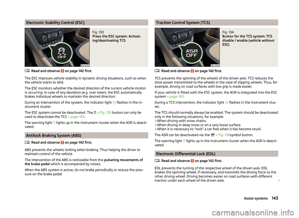
Electronic Stability Control (ESC)Fig. 133
Press the ESC system: Activat-
ing/deactivating TCS
Read and observe on page 142 first.
The ESC improves vehicle stability in dynamic driving situations, such as when
the vehicle starts to skid.
The ESC monitors whether the desired direction of the current vehicle motion
is occurring. In case of any deviation (e.g. over steer), the ESC automatically
brakes individual wheels to maintain the desired direction.
During an intervention of the system, the indicator light flashes in the in-
strument cluster.
The ESC system cannot be deactivated. The
» Fig. 133 button can only be
used to deactivate the TCS » page 143.
The warning light lights up in the instrument cluster when the ASR is deacti-
vated.
Antilock Braking System (ABS)
Read and observe
on page 142 first.
ABS prevents the wheels locking when braking. Thus helping the driver to
maintain control of the vehicle.
The intervention of the ABS is noticeable from the pulsating movements of
the brake pedal which is accompanied by noises.
When the ABS system is active, do not brake periodically or reduce the pres- sure on the brake pedal.
Traction Control System (TCS)Fig. 134
Button for the TCS system: TCS
disable / enable (vehicle without
ESC)
Read and observe on page 142 first.
TCS prevents the spinning of the wheels of the driven axle. TCS reduces the
drive power transmitted to the wheels in the case of slipping wheels. Thus, for
example, driving on road surfaces with low grip is made easier.
If your vehicle is fitted with the ESC system, the ASR is integrated into the ESC
system » page 143 .
During a TCS intervention, the indicator light flashes in the instrument clus-
ter.
The TCS should normally always be enabled. The system should be deactivated
only in the following situations, for example.
› When driving with snow chains.
› When driving in deep snow or on a very loose surface.
› When it is necessary to “rock” a car free when it has become stuck.
The ASR can be deactivated via the
» Fig. 134 symbol button.
The warning light lights up in the instrument cluster when the ASR is deacti-
vated.
Electronic Differential Lock (EDL)
Read and observe
on page 142 first.
EDL prevents the turning of the respective wheel of the driven axle. EDL
brakes the spinning wheel, if necessary, and transmits the driving force to the
other driving wheel. Driving becomes easier on road surfaces with different
traction under each wheel of the driven axle.
143Assist systems
Page 148 of 248
WARNING■A lack of fuel can cause irregular engine running or cause the engine to
shut down. This would lead the OFF ROAD mode to lose its effectiveness -
risk of accident!■
The increased safety offered by the OFF ROAD mode must not tempt you
to take greater risks than otherwise - risk of an accident!
■
Adjust the speed and driving style to the current visibility, weather, road
and traffic conditions.
CAUTION
■ The OFF ROAD mode is not designed for the use on common roads.■All four wheels must be fitted with the same tyres approved by the manufac-
turer to ensure theOFF ROAD mode operates correctly.
Operation
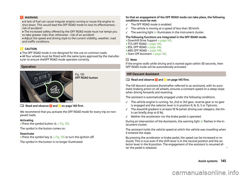
Fig. 135
OFF ROAD button
Read and observe and on page 145 first.
We recommend that you activate the OFF ROAD mode for every trip on non-
paved roads.
Activating
›
Press the symbol button
» Fig. 135 .
The symbol in the button comes on.
Deactivate
›
Press the symbol key
» Fig. 135 or turn the ignition off.
The symbol in the button is no longer illuminated.
So that an engagement of the OFF ROAD mode can take place, the following
conditions must be met.
The OFF ROAD mode is enabled.
The vehicle is moving at a speed of less than 30 km/h.
The warning light
illuminates in the instrument cluster.
The following functions are integrated in the OFF ROAD mode. › Downhill Drive Support
» page 145.
› TCS OFF ROAD
» page 146.
› EDL OFF ROAD
» page 146.
› ABS OFF ROAD
» page 146.
› Start-Off Assistant
» page 146.
Note
If the engine stalls while driving and is started again within 30 seconds, then
OFF ROAD mode will be automatically activated.
Hill Descent Assistant
Read and observe
and on page 145 first.
The hill descent assistant (hereinafter referred to as assistant), with its auto-
matic braking action on all wheels, ensures a constant speed on a steep slope
when driving forwards and reversing.
The assistant is automatically engaged under the following conditions. The vehicle engine is running. 1st, 2nd or 3rd gear, reverse gear or no gear
is engaged and the selector lever is in position R, N, D, S or Tiptronic.
The downhill gradient is at least 10 % (when driving over sleepers, the lim-
it can briefly drop to 8 %).
Neither the accelerator nor the brake pedal is operated.
During an intervention of the Assistants, the warning light flashes in the in-
strument cluster.
The assistant holds the vehicle speed at which the vehicle was travelling when
it entered the slope.
By pressing the accelerator or brake pedal, the speed can be increased or re-
duced. This is true even if the shift lever is in the neutral position and the se-
lector lever in the N position. The engagement of the assistant is resumed af-
ter the pedal is released.
145Assist systems
Page 149 of 248
For vehicles with manual transmission, the speed is maintained as follows.
› 1 gear - approx. 8 1)
- 30 km/h
› 2 gear - approx. 13 1 )
- 30 km/h
› 3 gear - approx. 22 1 )
- 30 km/h
› Reverse gear - approx. 9 1 )
- 30 km/h
› Neutral for driving forwards - as well as driving backwards - approx. 2 - 30
km/h
On vehicles with automatic transmission, the speed is maintained as follows.
› Position D, S, R or Tiptronic (for 1st, 2nd or 3rd gear) - approx. 2 - 30 km / h;
› Neutral for driving forwards - as well as reversing - approx. 2 - 30 km/hWARNINGFor the correct operation of the assistant the road surface must be suffi-
ciently adherent. The assistant cannot properly fulfil its function on slushy
soil due to physical reasons (e.g. ice or mud). - there is a risk of an accident!
Note
During an active intervention of the assistant, the brake lights do not light up.
TCSOFF ROAD
Read and observe
and on page 145 first.
The ASR OFF ROAD makes starting and driving on an unpaved surface easier
as it partially allows wheel-spin.
Note
When disabled, the TCS » Fig. 133 on page 143 OFF ROAD mode works without
the support of the TCS OFF ROAD.
EDS OFF ROAD
Read and observe
and on page 145 first.
The EDS supports OFF ROAD vehicle traction when driving on a surface withdifferent grip under the drive wheels or when driving over bumps.
A spinning wheel or wheels are braked earlier and with more force than with
the intervention of the standard EDS system.
ABS OFF ROAD
Read and observe
and on page 145 first.
The ABS OFF ROAD supports the driver when braking on an unpaved surface
such as gravel, snow, etc.
The system generated by a controlled locking of the wheels braked wheel be-
fore a “wedge” of piled material, which shortens the braking distance.
The system is only available, if the front wheels are in the straight-ahead posi-
tion.
The system operates at speeds of up to 50 km/h.
Start-Off Assistant 2)
Read and observe
and on page 145 first.
The Start-Off assistant assists the driver when setting off, such as on a steep
slope or on a slippery surface. When the driver presses the accelerator, the
maximum engine speed is electronically limited so that a gentle approach is
possible.
Parking aid
Introduction
This chapter contains information on the following subjects:
Function
147
Shown in the infotainment display
148
Activation/deactivation
148
The parking aid (hereinafter referred to only as system) draws attention via
acoustic signals or the Infotainment- or radio display 3)
when manoeuvring
around obstacles in the vicinity of the vehicle.
1)
The indicated values represent the average of the lower speed limits if a gear is engaged (depending on
the type of gearbox or engine).
2)
Only for vehicles with a petrol engine and manual transmission.
3)
Description of the display on the radio display » Radio instruction manual .
146Driving
Page 154 of 248

WARNING (Continued)■During a parking manoeuvre on loose or slippery surfaces (gravel, snow,
ice, etc.) you may stray from the calculated road because of the surface
conditions. Therefore we suggest that you do not use the system in such
situations.■
External noise sources may affect the signals of the system sensors. Un-
der adverse conditions, this may cause objects or people to not be recog-
nised by the system.
CAUTION
■ If other vehicles are parked behind the kerb or on it, the system can also
guide your vehicle beyond the kerb or onto it. Ensure that the wheels or the
wheel rims of your vehicle are not damaged and if necessary intervene in time.■
Under certain circumstances, surfaces or structures of certain objects such
as wire mesh fences or powder snow cannot be recognised by the system.
■
Under adverse weather conditions (heavy rain, water vapour, very low or
high temperatures etc.), the system function may be limited - “incorrect recog-
nition of obstacle”.
CAUTION
The correct evaluation of the parking space and the parking procedure de-
pends on the circumference of the wheels on the vehicle.■
The system only works correctly if the vehicle is fitted with the wheel size
approved by the manufacturer.
■
Do without the use of the system if snow chains or a spare wheel is moun-
ted.
■
If wheels other than those approved by the manufacturer are mounted, the
resulting position of the vehicle in the parking space can differ slightly. This
can be avoided by readjusting the system at a specialist garage.
Note
We recommend performing the parking at a safe speed to about 5 km / h.
Functioning
Read and observe
and on page 150 first.
Basic system operations
› The measurement and evaluation of the size of parking spaces when driving.
› The determination of the correct position of the vehicle for parking.
› The calculation of the line on which the vehicle drives backwards into the
parking space or forwards from the parking space.
› Automatic rotation of the front wheels during the parking.
The display of the instrument cluster (hereinafter only in the display) informa-
tion and system messages are displayed.
When the system is activated, the warning light lights up
» Fig. 141 on
page 151 -
.
The traction control system (TCS) must always be switched on when parking.
Finding a parking space
Fig. 141
System button / display
Read and observe
and on page 150 first.
Finding a parallel parking space
›
Drive past the parking space at up to 40 km/h and a distance of 0.5 – 1.5 m.
›
Press the symbol button once
» Fig. 141 .
The display shows the following » Fig. 141 -
.
Finding a perpendicular parking space
›
Drive past the parking space at up to 20 km/h and a distance of 0.5 – 1.5 m.
›
Press the symbol button twice
» Fig. 141 .
The display shows the following » Fig. 141 -
.
The search area for the parking space on the driver's side is automatically indi-
cated on the display.
Activate the turn signal on the driver's side if you wish to park on this side of
the road. In the display the search area for the parking space is indicated on
the driver's side.
151Assist systems
Page 158 of 248

After starting the system, the current speed is stored and the instrument clus-
ter lights up the warning light .
After the interruption in control, the stored speed can be resumed by pressing
the B
button.
Automatic control interruption
Automatic control interruption occurs if any of the following conditions are
met.
› By pressing the brake or clutch pedal.
› When one of the brake assist systems (e.g. ESC) intervenes.
› Through an airbag deployment.
WARNING■
Always deactivate the cruise control system after use to prevent the sys-
tem being switched on unintentionally.■
Control may only be resumed if the stored speed is not too high for the
current traffic conditions.
Note
During control, speed can be increased by pressing the accelerator pedal. Re-
leasing the accelerator pedal will cause the speed to drop again to the set
speed.
START-STOP
Introduction
This chapter contains information on the following subjects:
Operating conditions of the system
155
Operation in vehicles with manual gearbox
156
Operation in vehicles with automatic gearbox
156
System related automatic start-up
156
Manually deactivating/activating the system
157
Information messages
157
The START-STOP system (hereinafter referred to as the system) saves fuel and
reduces polluting emissions and CO 2 emissions by turning the engine off, e.g.
when stopping at traffic lights, and starting the engine again when moving off.
WARNING■ Never let the vehicle roll with the engine switched off.■The brake servo unit and power steering only operate if the engine is run-
ning.
Operating conditions of the system
Fig. 144
Maxi DOT display: Engine is auto-
matically switched off / automat-
ic engine cut off is not possible
Read and observe on page 155 first.
For system-dependent automatic engine shutdown
to work, the following conditions must be met.
The driver's door is closed.
The driver has fastened the seat belt.
The bonnet is closed.
The driving speed was higher than 4 km.h after the last stop.
No trailer is coupled.
Some additional conditions for the system to function correctly cannot be in-
fluenced or recognised by the driver. Therefore, the system can react differ-
ently in situations which are identical from the driver's perspective.
If after stopping the car, the message START-STOP NOT POSSIBLE appears in
the segment display or the
» Fig. 144 check mark appears in the MAXI DOT
display, then the conditions for automatic engine shutdown are not met.
Running the engine is essential for the following reasons, for example.
› The engine temperature for the proper function of the system has not yet
been reached.
› The charge state of the vehicle battery is too low.
› The current consumption is too high.
› High air-conditioning or heating capacity (high fan speed, big difference be-
tween the desired and actual interior temperature).
155Assist systems
Page 160 of 248

Manually deactivating/activating the systemFig. 145
Button for the START-STOP sys-
tem
Read and observe on page 155 first.
Deactivating/activating
›
Press the symbol button
» Fig. 145 .
When start-stop mode is deactivated, the indicator light in the button lights
up.
Note
If the system is deactivated when the engine is turned off automatically, then
the automatic start process takes place.
Information messages
Read and observe
on page 155 first.
The messages and information are indicated in the instrument cluster display. Start engine manually!
START MANUALLY
One of the conditions for automatic engine start is not satisfied or the driver's
seat belt is not fastened. The engine must be started manually.
On vehicles with the system KESSY the ignition is turned off by the first press
of the start button, only after pressing for the second time is the start process
initiated.
Error: Start-Stop system
ERROR START-STOP
A system error is present. Seek help from a specialist garage.
Fatigue detection (break recommendation)
Introduction
This chapter contains information on the following subjects:
Function
157
Information messages
158
The fatigue detection system (hereinafter referred to only as system) recom-
mends the driver taking a break from driving when, because of the driver's
steering behaviour, driver fatigue can be detected.
WARNING■ For the driving ability is always the driver's responsibility. Never drive if
you feel tired.■
The system may not detect all cases where a break is needed.
■
Therefore, take regular, sufficient breaks during long trips.
■
There will be no system warning during the so-called micro-sleep.
Note
■ In some situations, the system may evaluate the driving incorrectly and thus
mistakenly recommend a break (e.g. sporty driving, adverse weather condi-
tions or poor road conditions).■
The system is designed primarily for use on motorways.
Function
Read and observe
on page 157 first.
From the start of the journey, the system evaluates steering behaviour. If,
while driving, there have been changes in the steering behaviours that are
evaluated by the system as indicating possible fatigue, a break recommenda-
tion is issued.
The system evaluates steering behaviour and recommends a break at speeds
of 65-200 km / h.
The system detects a break from driving when one of the following condi-
tions is met.
› The vehicle is stopped and the ignition switched off.
› The vehicle is stopped, the seat belt removed and the driver's door opened.
› The vehicle is stopped for more than 15 minutes.
157Assist systems
Page 161 of 248
If none of these conditions are met or if the driving style is not changed, the
system recommends a driving break again after 15 minutes.
Activation/deactivation
The system can be activated/deactivated via the MAXI DOT display in the As-
sistants menu option » page 47.
Information messages
Read and observe
on page 157 first.
In MAXI DOT display the icon appears for a few seconds and the following
message.
Fatigue detected. Take a break!
An audible signal is also emitted.
Tyre pressure monitoring
Introduction
This chapter contains information on the following subjects:
Save tyre pressure values
158
The tyre pressure monitoring function (hereinafter referred to only as a sys-
tem) monitors the tyre pressure while driving.
If the rolling circumference of a wheel is changed, the warning light in the
instrument cluster lights up and an audible signal sounds.
Information on the procedure for the notification of change of tyre inflation
pressure » page 40 .
The system can only function properly if the tyres have the prescribed inflation
pressure and these pressure values are stored in the system.
WARNING■ Having the correct tyre inflation pressure is always the driver's responsi-
bility. Tyre pressure should be checked regularly » page 191.■
The system cannot warn in case of very rapid tyre inflation pressure loss,
e.g. in case of sudden tyre damage.
Save tyre pressure valuesFig. 146
Key for storing the pressure val-
ues
Read and observe on page 158 first.
Save the tyre pressure values as follows.
›
Inflate all the tyres to the specified pressure.
›
Switch on the ignition.
›
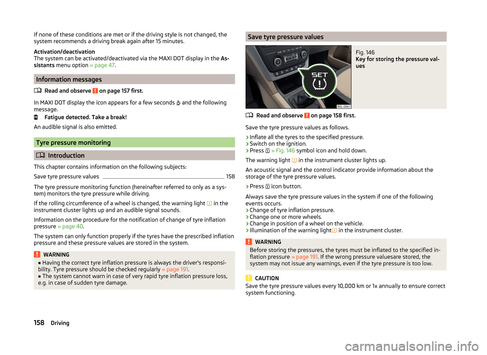
Press
» Fig. 146 symbol icon and hold down.
The warning light in the instrument cluster lights up.
An acoustic signal and the control indicator provide information about the
storage of the tyre pressure values.
›
Press icon button.
Always save the tyre pressure values in the system if one of the following
events occurs.
› Change of tyre inflation pressure.
› Change one or more wheels.
› Change in position of a wheel on the vehicle.
› Illumination of the warning light
in the instrument cluster.
WARNINGBefore storing the pressures, the tyres must be inflated to the specified in-
flation pressure » page 191. If the wrong pressure valuesare stored, the
system may not issue any warnings, even if the tyre pressure is too low.
CAUTION
Save the tyre pressure values every 10,000 km or 1x annually to ensure correct
system functioning.158Driving
Page 166 of 248
AccessoriesFig. 155
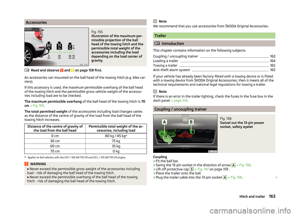
Illustration of the maximum per-
missible projection of the ball
head of the towing hitch and the
permissible total weight of the
accessories including the load
depending on the load center of
gravity.
Read and observe and on page 159 first.
An accessories can mounted on the ball head of the towing hitch (e.g. bike car-
riers).
If this accessory is used, the maximum permissible overhang of the ball head
of the towing hitch and the permissible gross vehicle weight of the accesso-
ries including load are to be checked.
The maximum permissible overhang of the ball head of the towing hitch is 70
cm » Fig. 155 .
The total permitted weight of the accessories including load changes varies
as the distance of the centre of gravity of the load from the ball head of the
towing hitch increases.
Distance of the centre of gravity of the load from the ball headPermissible total weight of the ac- cessories, including load0 cm80 kg / 85 kg a)30 cm75 kg60 cm35 kg70 cm0 kga)
Applies to 4x4 vehicles with the 2.0 l / 103 kW TDI CR and 2.0 L / 125 kW TDI CR engine.
WARNING■
Never exceed the permissible gross weight of the accessories including
load - risk of damaging the ball head of the towing hitch.■
Never exceed the permissible overhang of the ball head of the towing
hitch - risk of damaging the ball head of the towing hitch.
NoteWe recommend that you use accessories from ŠKODA Original Accessories.
Trailer
Introduction
This chapter contains information on the following subjects:
Coupling / uncoupling trainer
163
Loading a trailer
164
Towing a trailer
165
Anti-theft alarm system
165
If your vehicle has already been factory-fitted with a towing device or is fitted
with a towing device from ŠKODA Original Accessories, then it meets all of the
technical requirements and national legal regulations for towing a trailer.
Note
If there is an error in the trailer lighting, check the fuses in the fuse box in the
dash panel » page 214.
Coupling / uncoupling trainer
Fig. 156
Swivel out the 13-pin power
socket, safety eyelet
Coupling
›
Fit the ball bar.
›
Swing the 13-pin socket in the direction of arrow
A
» Fig. 156 .
›
Lift off protective cap
5
» Fig. 147 on page 159 .
›
Place the trailer onto the ball.
›
Plug the trailer cable into the 13-pin socket
A
» Fig. 156 .
163Hitch and trailer