key SKODA YETI 2015 1.G / 5L Owner's Guide
[x] Cancel search | Manufacturer: SKODA, Model Year: 2015, Model line: YETI, Model: SKODA YETI 2015 1.G / 5LPages: 232, PDF Size: 30.84 MB
Page 109 of 232
If the symbol illuminates at the end of the numeric scale then the Climatronic
works with maximum heating (temperature setting above +26 °C).
There is no automatic temperature control in the two end positions.
Controlling blower
The Climatronic system controls the blower stages automatically in line with the interior temperature. However, the blower stages can be manually adap-
ted to suit your particular needs.
If the blower speed is reduced to a minimum, Climatronic is switched off.
The set blower speed is displayed above the symbol button
when the re-
spective number of indicator lights come on.WARNING■ Do not switch off the Climatronic system for longer than necessary.■Switch on the Climatronic system as soon as the windows mist up.
CAUTION
Do not cover the interior temperature sensor B » Fig. 124 as this could impair
the functioning of the Climatronic.
Note
■ If the windscreen mists up, press the symbol button . Press the button
once the windscreen has demisted.■
During operation of the Climatronic, an increase in engine idle speed can oc-
cur under certain circumstances in order to ensure adequate heating comfort.
Climatronic - automatic operation
Read and observe
and on page 105 first.
The automatic mode is used in order to maintain a constant temperature andto demist the windows in the interior of the car.
If the warning light in the top right corner of the button lights up, the Cli-
matronic operates in “HIGH”-mode.
Upon pressing the button again, the Climatronic switches to “LOW”-mode
and the indicator light in the top left corner lights up. The Climatronic uses on-
ly in this mode the lower blower speed. However taking into account the noise
level, this is more comfortable, yet be aware that the effectiveness of the air
conditioning system is reduced particularly if the vehicle is fully occupied.
By pressing the button again, it is changed to “HIGH”-mode.
Automatic mode can be switched off by pressing one of the buttons for the air
distribution or by increasing/decreasing the blower speed. The temperature
regulation is continued.
Note
Climatronic is set to the “HIGH” mode at the factory.
Air distribution control
Read and observe
and on page 105 first.
The recirculation mode prevents contaminated outside air getting into the in-
terior of the vehicle.
In recirculated air mode air is sucked out of the interior of the vehicle and then
fed back into the interior.
Heating and manual air conditioning system
›
To turn the recirculation mode on or off, press the Symbol key
.
The air recirculation mode is automatically turned off by turning the air distri-
bution control
C
to position
» Fig. 122 on page 105 or » Fig. 123 on
page 105 .
Recirculated air mode can be switched on again from this position by repeat-
edly pressing the symbol button .
Climatronic (automatic air conditioning)
›
To turn the recirculation mode on, press the Symbol key
repeatedly until
the indicator light is lit on the left side of the button.
›
To activate the automatic recirculation mode, press the Symbol key
re-
peatedly until the indicator light is lit on the right side of the button.
Climatronic has an air quality sensor for the detection of the pollutant concen-
tration in the sucked-in air.
If a considerable increase in concentration of pollutants is recognised by the
air quality sensor, recirculated air mode will temporarily be switched on.
If the concentration of pollutants decreases to the normal level, the air distri-
bution control is automatically switched off so that fresh air can be guided into
the vehicle interior.
107Heating and ventilation
Page 112 of 232
WARNING■The auxiliary heating (auxiliary heating and ventilation) (hereinafter refer-
red to as aux. heating) must never be operated in closed rooms (e.g. garag-
es) – risk of poisoning!■
The auxiliary heating must not be allowed to run during refuelling – risk
of fire.
■
The exhaust pipe of the auxiliary heating is located on the underside of
the vehicle. If you want to use the heater, do not switch off the car in pla-
ces where the exhaust fumes can come into contact with flammable mate-
rials such as dry grass, undergrowth, leaves, spilled fuel etc. -. risk of fire.
CAUTION
■ The exhaust pipe of the auxiliary heating, which is located on the underside
of the vehicle, must not be clogged and the exhaust flow must not be blocked.■
If the auxiliary heating is running, the vehicle battery discharges. If the auxili-
ary heating and ventilation has been operated several times over a longer peri-
od, the vehicle must be driven a few kilometres in order to recharge the vehi-
cle battery.
■
The air inlet in front of the windscreen must be free (e.g. of ice, snow or
leaves) to ensure that the auxiliary heating operates properly.
Note
■ The auxiliary heating only switches the blower on, if it has achieved a coolant
temperature of approx. 50 °C.■
At low outside temperatures, this can result in a formation of water vapour in
the area of the engine compartment. This is quite normal and is not an operat-
ing problem.
■
So that warm air can flow into the vehicle interior after switching on the aux.
heating, you must maintain the comfort temperature normally selected by you,
leave the fan switched on and leave the air outlet vents in open. It is recom-
mended to put the air flow in the position
or
.
Switching on and off directlyFig. 127
Button for switching on/off the system directly on the operating
part of the air conditioning/Climatronic
Read and observe
and on page 110 first.
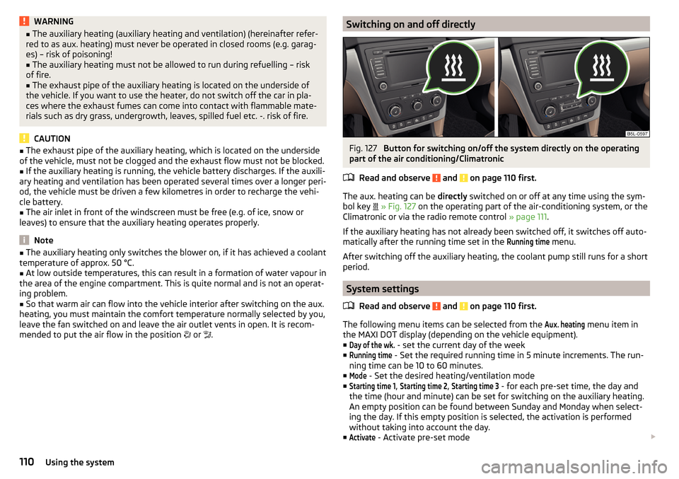
The aux. heating can be directly switched on or off at any time using the sym-
bol key
» Fig. 127 on the operating part of the air-conditioning system, or the
Climatronic or via the radio remote control » page 111.
If the auxiliary heating has not already been switched off, it switches off auto-
matically after the running time set in the
Running time
menu.
After switching off the auxiliary heating, the coolant pump still runs for a short
period.
System settings
Read and observe
and on page 110 first.
The following menu items can be selected from the
Aux. heating
menu item in
the MAXI DOT display (depending on the vehicle equipment). ■
Day of the wk.
- set the current day of the week
■
Running time
- Set the required running time in 5 minute increments. The run-
ning time can be 10 to 60 minutes.
■
Mode
- Set the desired heating/ventilation mode
■
Starting time 1
,
Starting time 2
,
Starting time 3
- for each pre-set time, the day and
the time (hour and minute) can be set for switching on the auxiliary heating.
An empty position can be found between Sunday and Monday when select-
ing the day. If this empty position is selected, the activation is performed
without taking into account the day.
■
Activate
- Activate pre-set mode
110Using the system
Page 115 of 232
Driving
Starting-off and Driving
Starting and stopping the engine using the key
Introduction
This chapter contains information on the following subjects:
Electronic immobilizer
113
Steering lock locking / unlocking
114
Turn ignition on / off and start the engine
114
Stopping the engine
114
With the key in the ignition, the ignition can be switched on and off and the
engine can be started / stopped.
WARNING■ While driving with the engine stopped, the ignition must always be
switched on » page 114, Turn ignition on / off and start the engine .
■ With the ignition off, the steering may lock » page 114 - danger of an
accident!■
Do not withdraw the ignition key from the ignition lock until the vehicle
has come to a stop » page 121, Parking . Otherwise, the steering may lock -
danger of an accident!
■
Never leave the key in the vehicle when you exit the vehicle. Unauthor-
ized persons, such as children, for example, could lock the car, turn on the
ignition or start the engine - there is a danger of injury, damage and acci-
dents!
■
Never leave the vehicle unattended with the engine running - there is
risk of accident, damage or theft!
■
Never switch off the engine before the vehicle is stationary – risk of acci-
dent!
WARNING■ Never (e.g. in garages) run the engine in a closed place - there is the dan-
ger of poisoning and death!■
Do not leave any items (e.g. cloths or tools) in the engine compartment.
This presents a fire hazard and the risk of engine damage.
■
Never cover the engine with additional insulation material (e.g. with a
cover) – risk of fire!
CAUTION
■ Only start the engine when the engine and the vehicle are stationary - there
is a danger of starter and engine damage!■
Do not push-start the engine – risk of damaging the engine and the catalytic
converter. The battery from another vehicle can be used as a jump-start aid
» page 189 .
Note
Do not warm up the engine while the vehicle is stationary. If possible, start
your journey as soon as the engine has started. Through this, the engine rea-
ches its operating temperature faster.
Electronic immobilizer
Read and observe
and on page 113 first.
The electronic immobiliser (hereinafter referred to as immobiliser) makes the
attempted theft or unauthorised use of your vehicle more difficult.
An electronic chip is integrated in the head of the key. The immobiliser is deac-
tivated with the aid of this chip when the key is inserted in the ignition lock.
As soon as the ignition key is removed from the ignition lock, the immobiliser is
automatically activated.
Operational problems
If a component in the immobiliser key fails, it is not possible to start the en-
gine. A corresponding message appears in the display of the instrument clus-
ter to explain the immobiliser is active.
To start, use the other vehicle key or seek help from a specialist garage.
113Starting-off and Driving
Page 116 of 232
Steering lock locking / unlockingRead and observe
and on page 113 first.
The steering lock (steering lock) deters any attempted theft of your vehicle.
Locking
›
Withdraw the ignition key.
›
Turn the steering wheel to the left or right until the steering lock clicks into
place.
Unlocking
›
Insert the key into the ignition lock.
›
Switch on the ignition » page 114.
The steering wheel is unlocked.
If the ignition switch cannot be turned on, then turn the steering wheel back
and forth slightly and thereby unlock the steering lock.
Turn ignition on / off and start the engine
Fig. 129
Positions of the vehicle key in the ignition lock
Read and observe and on page 113 first.
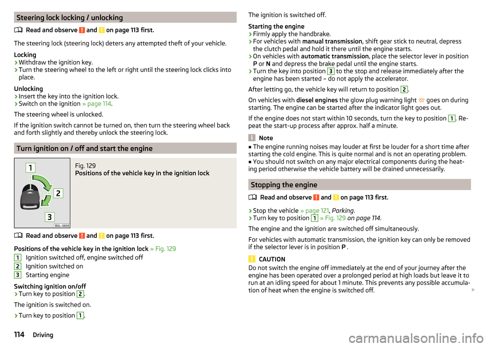
Positions of the vehicle key in the ignition lock » Fig. 129
Ignition switched off, engine switched off
Ignition switched on
Starting engine
Switching ignition on/off
›
Turn key to position
2
.
The ignition is switched on.
›
Turn key to position
1
.
123The ignition is switched off.
Starting the engine›
Firmly apply the handbrake.
›
For vehicles with manual transmission , shift gear stick to neutral, depress
the clutch pedal and hold it there until the engine starts.
›
On vehicles with automatic transmission , place the selector lever in position
P or N and depress the brake pedal until the engine starts.
›
Turn the key into position
3
to the stop and release immediately after the
engine has been started – do not apply the accelerator.
After letting go, the vehicle key will return to position
2
.
On vehicles with diesel engines the glow plug warning light
goes on during
starting. The engine can be started after the indicator light goes out.
If the engine does not start within 10 seconds, turn the key to position
1
. Re-
peat the start-up process after approx. half a minute.
Note
■ The engine running noises may louder at first be louder for a short time after
starting the cold engine. This is quite normal and is not an operating problem.■
You should not switch on any major electrical components during the heat-
ing period otherwise the vehicle battery will be drained unnecessarily.
Stopping the engine
Read and observe
and on page 113 first.
›
Stop the vehicle » page 121, Parking .
›
Turn key to position
1
» Fig. 129 on page 114 .
The engine and the ignition are switched off simultaneously.
For vehicles with automatic transmission, the ignition key can only be removed
if the selector lever is in position P .
CAUTION
Do not switch the engine off immediately at the end of your journey after the
engine has been operated over a prolonged period at high loads but leave it to
run at an idling speed for about 1 minute. This prevents any possible accumula-
tion of heat when the engine is switched off. 114Driving
Page 117 of 232
NoteAfter switching off the ignition, the radiator fan may intermittently continue to
operate for approx. 10 minutes.
Starting and stopping the engine at the push of the button
Introduction
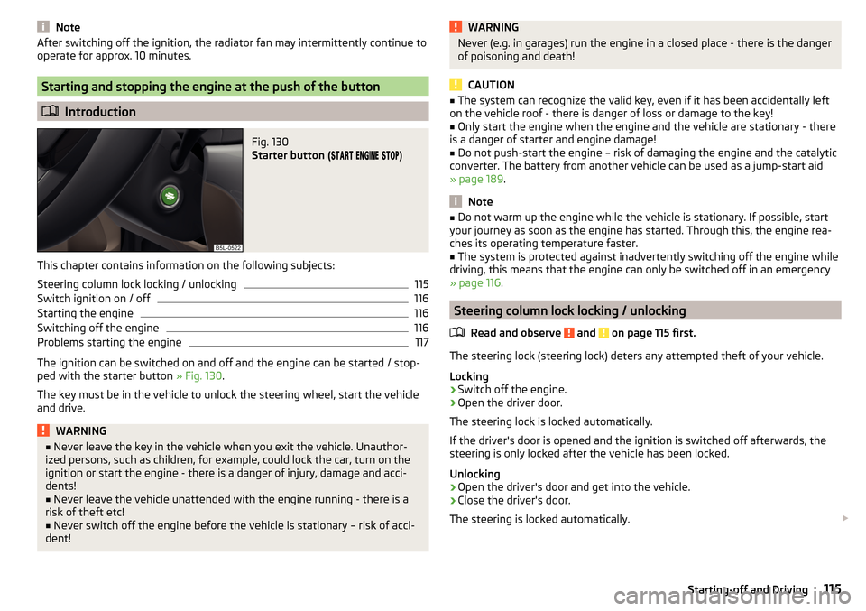
Fig. 130
Starter button (
)
This chapter contains information on the following subjects:
Steering column lock locking / unlocking
115
Switch ignition on / off
116
Starting the engine
116
Switching off the engine
116
Problems starting the engine
117
The ignition can be switched on and off and the engine can be started / stop-
ped with the starter button » Fig. 130.
The key must be in the vehicle to unlock the steering wheel, start the vehicle
and drive.
WARNING■ Never leave the key in the vehicle when you exit the vehicle. Unauthor-
ized persons, such as children, for example, could lock the car, turn on the
ignition or start the engine - there is a danger of injury, damage and acci-
dents!■
Never leave the vehicle unattended with the engine running - there is a
risk of theft etc!
■
Never switch off the engine before the vehicle is stationary – risk of acci-
dent!
WARNINGNever (e.g. in garages) run the engine in a closed place - there is the danger
of poisoning and death!
CAUTION
■ The system can recognize the valid key, even if it has been accidentally left
on the vehicle roof - there is danger of loss or damage to the key!■
Only start the engine when the engine and the vehicle are stationary - there
is a danger of starter and engine damage!
■
Do not push-start the engine – risk of damaging the engine and the catalytic
converter. The battery from another vehicle can be used as a jump-start aid
» page 189 .
Note
■
Do not warm up the engine while the vehicle is stationary. If possible, start
your journey as soon as the engine has started. Through this, the engine rea-
ches its operating temperature faster.■
The system is protected against inadvertently switching off the engine while
driving, this means that the engine can only be switched off in an emergency
» page 116 .
Steering column lock locking / unlocking
Read and observe
and on page 115 first.
The steering lock (steering lock) deters any attempted theft of your vehicle.
Locking
›
Switch off the engine.
›
Open the driver door.
The steering lock is locked automatically.
If the driver's door is opened and the ignition is switched off afterwards, the
steering is only locked after the vehicle has been locked.
Unlocking
›
Open the driver's door and get into the vehicle.
›
Close the driver's door.
The steering is locked automatically.
115Starting-off and Driving
Page 119 of 232
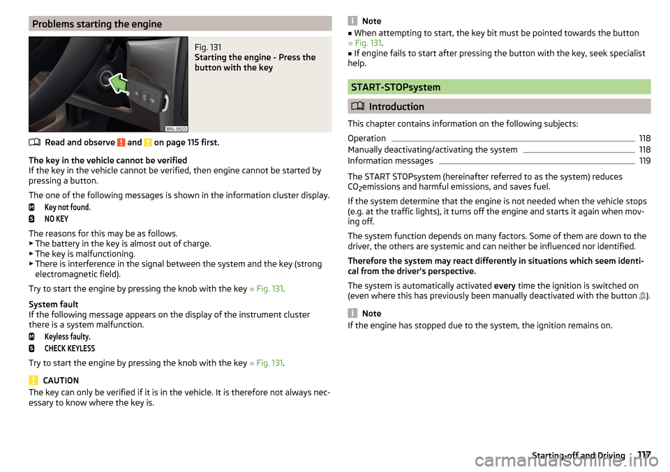
Problems starting the engineFig. 131
Starting the engine - Press the
button with the key
Read and observe and on page 115 first.
The key in the vehicle cannot be verified
If the key in the vehicle cannot be verified, then engine cannot be started by pressing a button.
The one of the following messages is shown in the information cluster display.
Key not found.NO KEY
The reasons for this may be as follows.
▶ The battery in the key is almost out of charge.
▶ The key is malfunctioning.
▶ There is interference in the signal between the system and the key (strong
electromagnetic field).
Try to start the engine by pressing the knob with the key » Fig. 131.
System fault
If the following message appears on the display of the instrument cluster
there is a system malfunction.
Keyless faulty.CHECK KEYLESS
Try to start the engine by pressing the knob with the key » Fig. 131.
CAUTION
The key can only be verified if it is in the vehicle. It is therefore not always nec-
essary to know where the key is.Note■ When attempting to start, the key bit must be pointed towards the button
» Fig. 131 .■
If engine fails to start after pressing the button with the key, seek specialist
help.
START-STOPsystem
Introduction
This chapter contains information on the following subjects:
Operation
118
Manually deactivating/activating the system
118
Information messages
119
The START STOPsystem (hereinafter referred to as the system) reduces
CO 2emissions and harmful emissions, and saves fuel.
If the system determine that the engine is not needed when the vehicle stops
(e.g. at the traffic lights), it turns off the engine and starts it again when mov-
ing off.
The system function depends on many factors. Some of them are down to the
driver, the others are systemic and can neither be influenced nor identified.
Therefore the system may react differently in situations which seem identi-
cal from the driver's perspective.
The system is automatically activated every time the ignition is switched on
(even where this has previously been manually deactivated with the button ).
Note
If the engine has stopped due to the system, the ignition remains on.117Starting-off and Driving
Page 124 of 232
Automatic transmission
Introduction
This chapter contains information on the following subjects:
Modes and use of selector lever
122
Selector lever lock
123
Manual shifting of gears (Tiptronic)
123
Starting-off and driving
124
The automatic transmission performs automatic gear changes.
The modes of the automatic transmission can be adjusted by the driver by
means of the selector lever.
WARNING■ No throttle when it is set before starting the mode for moving forward
with the selector lever - there is a risk of accident!■
Never move the selector lever to mode R or P when driving – risk of an
accident!
■
If the vehicle is in the mode selected D, S , R or Tiptronic and the engine
stops when at idle speed, then the brake pedal must be pressed. Even
when the engine is idling, the power transmission is never completely in-
terrupted – the vehicle creeps.
■
When leaving the vehicle, the selector lever is always to put in the P
mode. Otherwise, the vehicle could be set in motion - risk of accident!
CAUTION
■ If the selector lever is moved to mode N while driving, the accelerator pedal
must be released and you will need to wait until the engine has reached its
idling speed before moving the selector lever to a forward driving mode again.■
When the outdoor temperature is below -10 ° C, the selector lever when
starting must always be in P mode.
■
When stopping on a slope, never try to hold the vehicle using the accelerator
pedal – this may lead to gear damage.
Note
After the ignition is switched off, the ignition key can only be withdrawn if the
selector lever is in the position P.Modes and use of selector leverFig. 136
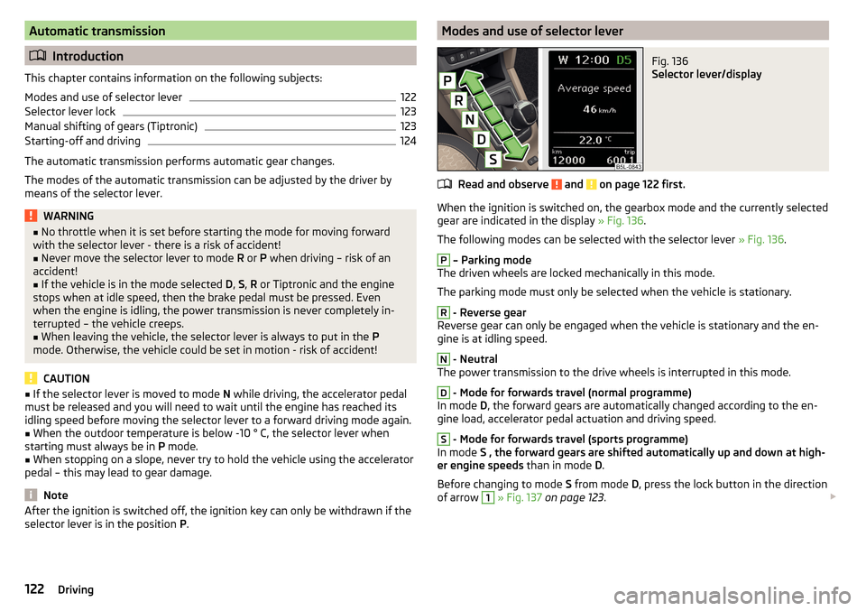
Selector lever/display
Read and observe and on page 122 first.
When the ignition is switched on, the gearbox mode and the currently selected
gear are indicated in the display » Fig. 136.
The following modes can be selected with the selector lever » Fig. 136.
P
– Parking mode
The driven wheels are locked mechanically in this mode.
The parking mode must only be selected when the vehicle is stationary.
R
- Reverse gear
Reverse gear can only be engaged when the vehicle is stationary and the en-
gine is at idling speed.
N
- Neutral
The power transmission to the drive wheels is interrupted in this mode.
D
- Mode for forwards travel (normal programme)
In mode D, the forward gears are automatically changed according to the en-
gine load, accelerator pedal actuation and driving speed.
S
- Mode for forwards travel (sports programme)
In mode S , the forward gears are shifted automatically up and down at high-
er engine speeds than in mode D.
Before changing to mode S from mode D, press the lock button in the direction
of arrow
1
» Fig. 137 on page 123 .
122Driving
Page 131 of 232
The HHC is active from a 5% slope if the driver's door is closed. HHC is only ev-
er active on slopes when in forward or reverse start off.
Trailer stabilization system (TSA)
Read and observe
on page 127 first.
The TSA helps the combination stable in situations where the trailer sways
and then the whole trailer combination.
TSA brakes the individual wheels of the towing vehicle in order to damp the
rocking motion of the entire vehicle combination.
The following conditions are required for the correct TSA function. The trailer was shipped from the factory or purchased from the ŠKODA
genuine accessories.
The trailer is electrically connected to the towing vehicle via the trailer
socket.
The TCS is activated.
The speed is higher than approx. 60 km/h.
Further information » page 141, Hitch and trailer .
OFF ROAD-mode
Introduction
This chapter contains information on the following subjects:
Operation
129
Hill Descent Assistant
130
TCSOFF ROAD
130
EDS OFF ROAD
130
ABS OFF ROAD
130
Start-Off Assistant
131
The OFF ROAD mode includes several features that help to overcome difficult
navigable routes when travelling on non-paved roads.
But even with OFF ROAD mode activated, your vehicle is never a true SUV.
WARNING■ The general information relating to the use of assistance systems must
be observed » page 127, in section Introduction .■
A lack of fuel can cause irregular engine running or cause the engine to
shut down. This would lead the OFF ROAD mode to lose its effectiveness -
risk of accident!
CAUTION
■ The OFF ROAD mode is not designed for the use on common roads.■All four wheels must be fitted with the same tyres approved by the manufac-
turer to ensure theOFF ROAD mode operates correctly.
Operation
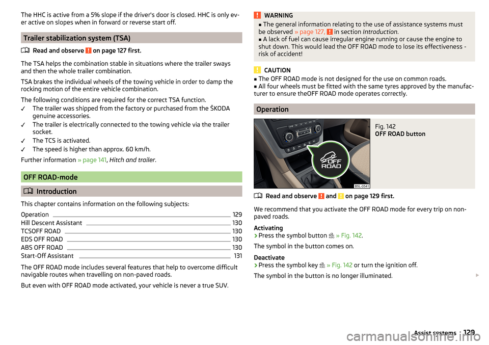
Fig. 142
OFF ROAD button
Read and observe and on page 129 first.
We recommend that you activate the OFF ROAD mode for every trip on non- paved roads.
Activating
›
Press the symbol button
» Fig. 142 .
The symbol in the button comes on.
Deactivate
›
Press the symbol key
» Fig. 142 or turn the ignition off.
The symbol in the button is no longer illuminated.
129Assist systems
Page 134 of 232
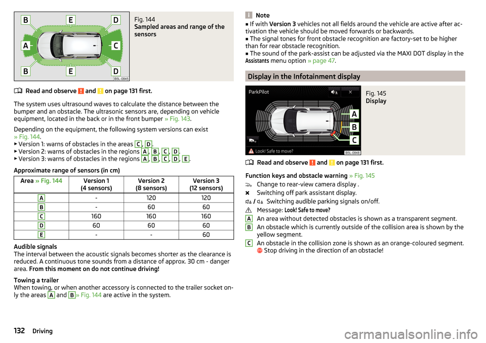
Fig. 144
Sampled areas and range of the
sensors
Read and observe and on page 131 first.
The system uses ultrasound waves to calculate the distance between the
bumper and an obstacle. The ultrasonic sensors are, depending on vehicle
equipment, located in the back or in the front bumper » Fig. 143.
Depending on the equipment, the following system versions can exist
» Fig. 144 .
▶ Version 1: warns of obstacles in the areas
C
,
D
.
▶ Version 2: warns of obstacles in the regions
A
,
B
,
C
,
D
.
▶ Version 3: warns of obstacles in the regions
A
,
B
,
C
,
D
,
E
.
Approximate range of sensors (in cm)
Area » Fig. 144Version 1
(4 sensors)Version 2
(8 sensors)Version 3
(12 sensors)A-120120B-6060C160160160D606060E--60
Audible signals
The interval between the acoustic signals becomes shorter as the clearance is
reduced. A continuous tone sounds from a distance of approx. 30 cm - danger
area. From this moment on do not continue driving!
Towing a trailer
When towing, or when another accessory is connected to the trailer socket on-
ly the areas
A
and
B
» Fig. 144 are active in the system.
Note■
If with Version 3 vehicles not all fields around the vehicle are active after ac-
tivation the vehicle should be moved forwards or backwards.■
The signal tones for front obstacle recognition are factory-set to be higher
than for rear obstacle recognition.
■
The sound of the park-assist can be adjusted via the MAXI DOT display in the
Assistants
menu option » page 47.
Display in the Infotainment display
Fig. 145
Display
Read and observe and on page 131 first.
Function keys and obstacle warning » Fig. 145
Change to rear-view camera display .
Switching off park assistant display. Switching audible parking signals on/off.
Message:
Look! Safe to move?
An area without detected obstacles is shown as a transparent segment.
An obstacle which is currently outside of the collision area is shown by the
yellow segment.
An obstacle in the collision zone is shown as an orange-coloured segment.
Stop driving in the direction of an obstacle!
ABC132Driving
Page 135 of 232
Activation/deactivationFig. 146
System key (option 2, 3)
Read and observe and on page 131 first.
Activation
The activation of the system is initiated when the reverse gear is engaged, or
vehicles with the Variant 2 and 3 , also by pressing the symbol key
» Fig. 146 .
This is confirmed by a short acoustic signal ( the symbol in the button is lit).
Deactivation
On vehicles with Version 1, the system can be deactivated by moving out of re-
verse gear.
For vehicles with the Version 2 and 3 the system is automatically deactivated
by pressing the symbol key or at a speed over 15 km / h (the symbol
in the
button goes out).
Fault display
If a warning signal sounds for about 3 seconds after activating the system and
there is no obstacle close to your car, this indicates a system fault. The fault is
also indicated by the symbol flashing in the button. Seek help from a spe-
cialist garage.
Note
The system can only be activated with the symbol key at a speed of below
15 km / hr.Rear View Camera
Introduction
This chapter contains information on the following subjects:
Operation
134
Guidelines and function keys
134
The rear view camera (hereinafter referred to as system) helps the driver when
parking and manoeuvring by displaying the area behind the vehicle in the Info-
tainment display (hereinafter referred to as display).
WARNING■ The general information relating to the use of assistance systems must
be observed » page 127, in section Introduction .■
Make sure that the camera lens is not dirty or covered, otherwise the sys-
tem function can be significantly impaired. For information on cleaning
» page 156 , Camera lens
CAUTION
■
The camera lens distorts and enlarges the field of view of the difference in
eye sight. The display is therefore only of limited use for estimating distances
to following vehicles.■
Some items, such as thin columns, chain link fences or lattice may not be
represented adequately in terms of display resolution.
■
It is only a two-dimensional display. Therefore, protruding objects or roadway
depressions, for example, may not be recognised due to lack of space depth.
■
In a crash or damage the vehicle's rear camera can possibly deviate from the
correct position. If this is the case, have the sensor checked by a specialist ga-
rage.
133Assist systems