key SKODA YETI 2015 1.G / 5L Owner's Guide
[x] Cancel search | Manufacturer: SKODA, Model Year: 2015, Model line: YETI, Model: SKODA YETI 2015 1.G / 5LPages: 232, PDF Size: 30.84 MB
Page 64 of 232
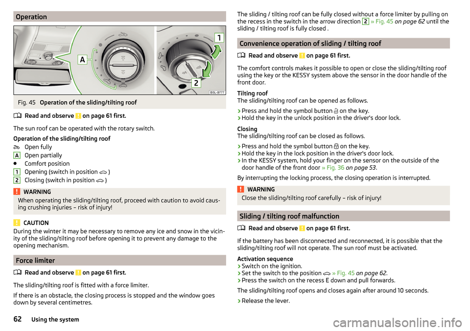
OperationFig. 45
Operation of the sliding/tilting roof
Read and observe
on page 61 first.
The sun roof can be operated with the rotary switch.
Operation of the sliding/tilting roof Open fully
Open partially
Comfort position
Opening (switch in position )
Closing (switch in position )
WARNINGWhen operating the sliding/tilting roof, proceed with caution to avoid caus-
ing crushing injuries – risk of injury!
CAUTION
During the winter it may be necessary to remove any ice and snow in the vicin-
ity of the sliding/tilting roof before opening it to prevent any damage to the
opening mechanism.
Force limiter
Read and observe
on page 61 first.
The sliding/tilting roof is fitted with a force limiter.
If there is an obstacle, the closing process is stopped and the window goes
down by several centimetres.
A12The sliding / tilting roof can be fully closed without a force limiter by pulling on
the recess in the switch in the arrow direction 2 » Fig. 45 on page 62 until the
sliding / tilting roof is fully closed .
Convenience operation of sliding / tilting roof
Read and observe
on page 61 first.
The comfort controls makes it possible to open or close the sliding/tilting roof
using the key or the KESSY system above the sensor in the door handle of the
front door.
Tilting roof
The sliding/tilting roof can be opened as follows.
›
Press and hold the symbol button on the key.
›
Hold the key in the unlock position in the driver's door lock.
Closing
The sliding/tilting roof can be closed as follows.
›
Press and hold the symbol button on the key.
›
Hold the key in the lock position in the driver's door lock.
›
In the KESSY system, hold your finger on the sensor on the outside of the
door handle of the front door » Fig. 36 on page 53 .
By interrupting the locking process, the closing operation is interrupted.
WARNINGClose the sliding/tilting roof carefully – risk of injury!
Sliding / tilting roof malfunction
Read and observe
on page 61 first.
If the battery has been disconnected and reconnected, it is possible that thesliding/tilting roof will not operate. The sun roof must be activated.
Activation sequence
›
Switch on the ignition.
›
Set the switch to the position
» Fig. 45 on page 62 .
›
Press the switch on the recess E down and pull forwards.
The sliding/tilting roof opens and closes again after around 10 seconds.
›
Release the lever.
62Using the system
Page 65 of 232
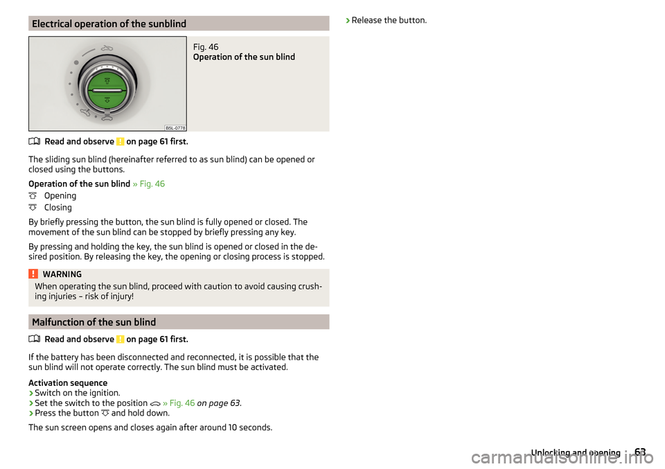
Electrical operation of the sunblindFig. 46
Operation of the sun blind
Read and observe on page 61 first.
The sliding sun blind (hereinafter referred to as sun blind) can be opened orclosed using the buttons.
Operation of the sun blind » Fig. 46
Opening
Closing
By briefly pressing the button, the sun blind is fully opened or closed. The
movement of the sun blind can be stopped by briefly pressing any key.
By pressing and holding the key, the sun blind is opened or closed in the de-
sired position. By releasing the key, the opening or closing process is stopped.
WARNINGWhen operating the sun blind, proceed with caution to avoid causing crush- ing injuries – risk of injury!
Malfunction of the sun blind
Read and observe
on page 61 first.
If the battery has been disconnected and reconnected, it is possible that thesun blind will not operate correctly. The sun blind must be activated.
Activation sequence
›
Switch on the ignition.
›
Set the switch to the position
» Fig. 46 on page 63 .
›
Press the button
and hold down.
The sun screen opens and closes again after around 10 seconds.
› Release the button.63Unlocking and opening
Page 67 of 232
WARNINGAlways adjust the headlight beam to meet the following conditions.■The vehicle does not dazzle other road users, especially oncoming vehi-
cles.■
The beam range is sufficient for safe driving.
Note
■ The light switch is in position or and the ignition is turned off, the low
beam is switched off automatically 1)
and the status light is lit. The side light is
switched off when the ignition key is removed, for vehicles with the KESSY
system after switching off the ignition and opening the driver's door.■
If there is a fault in the light switch, the low beam comes on automatically.
Daylight running lights (DAY LIGHT)
Read and observe
on page 64 first.
The daytime running light (hereinafter referred to as "function") lights the
front and rear vehicle area (only valid for some countries).
The daytime running lights are switched on automatically if the following
conditions are met.
The light switch is in the position
or
.
The ignition is switched on.
The function is activated.
Function for vehicles with MAXI DOT display disable / enable
The function menu item
Dayt. r. light
can be deactivated / activated » page 47,
Menu item
Settings
.
Disable function for vehicles with segment display
›
Switch off the ignition.
›
Pull the indicator / main beam lever towards the steering wheel, push down
and hold in this position.
›
Switch on the ignition.
›
Hold the lever in this position for min. 3 seconds after switching on the igni-
tion.
The deactivation of the function is confirmed by an audible signal.
Enable function for vehicles with segment display›Switch off the ignition.›
Pull the indicator / main beam lever towards the steering wheel, push up and
hold in this position.
›
Switch on the ignition.
›
Hold the lever in this position for min. 3 seconds after switching on the igni-
tion.
The activation of the function is confirmed by an audible signal.
WARNINGAlways switch on the low beam when visibility is poor.
Turn signal and main beam
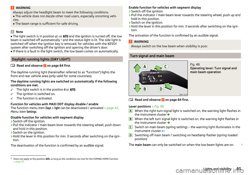
Fig. 48
Operating lever: Turn signal and
main beam operation
Read and observe on page 64 first.
Lever positions » Fig. 48
When the right turn signal light is switched on, the warning light flashes in
the instrument cluster
When the left turn signal light is switched on, the warning light flashes in
the instrument cluster
Switch on main beam (spring setting) – the warning light illuminates in the
instrument cluster
Switching off main beam / switching on headlamp flasher (spring-loaded position)
The main beam can only be switched on when the low beam lights are on.
ABCD1)
Does not apply to the position
, as long as the conditions are met for the COMING HOME function
» page 67 .
65Lights and visibility
Page 70 of 232
The function LEAVING HOME ensures that the vehicle's environment is illumi-
nated after unlocking the vehicle with the radio remote control unit.
The function switches the light on only if there is poorer visibility and the light
switch is in the position
.
Enabling / disabling and setting function
The functions and settings of the illumination time can be activated / deactiva-
ted via the MAXI DOT display in the menu items Coming Home
or
Leaving Home
» page 47 .
CAUTION
■
Poorer visibility is evaluated by a motor mounted below the windscreen in
the holder of the interior mirror sensor. Do not attach any stickers or similar
objects in front of the light sensor on the windscreen in order to avoid impair-
ing the function or its reliability.■
If this option is always enabled, then the battery is heavily loaded.
Hazard warning light system
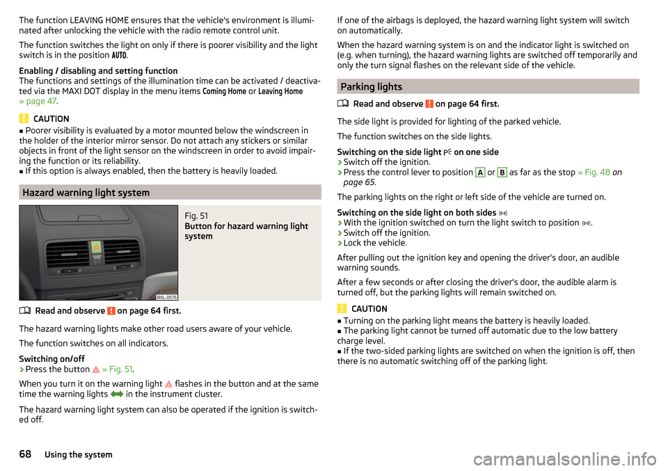
Fig. 51
Button for hazard warning light
system
Read and observe on page 64 first.
The hazard warning lights make other road users aware of your vehicle.
The function switches on all indicators.
Switching on/off
›
Press the button
» Fig. 51 .
When you turn it on the warning light
flashes in the button and at the same
time the warning lights
in the instrument cluster.
The hazard warning light system can also be operated if the ignition is switch-
ed off.
If one of the airbags is deployed, the hazard warning light system will switch
on automatically.
When the hazard warning system is on and the indicator light is switched on
(e.g. when turning), the hazard warning lights are switched off temporarily and
only the turn signal flashes on the relevant side of the vehicle.
Parking lights
Read and observe
on page 64 first.
The side light is provided for lighting of the parked vehicle.
The function switches on the side lights.
Switching on the side light on one side
›
Switch off the ignition.
›
Press the control lever to position
A
or
B
as far as the stop
» Fig. 48 on
page 65 .
The parking lights on the right or left side of the vehicle are turned on.
Switching on the side light on both sides
›
With the ignition switched on turn the light switch to position .
›
Switch off the ignition.
›
Lock the vehicle.
After pulling out the ignition key and opening the driver's door, an audible
warning sounds.
After a few seconds or after closing the driver's door, the audible alarm is
turned off, but the parking lights will remain switched on.
CAUTION
■ Turning on the parking light means the battery is heavily loaded.■The parking light cannot be turned off automatic due to the low battery
charge level.■
If the two-sided parking lights are switched on when the ignition is off, then
there is no automatic switching off of the parking light.
68Using the system
Page 71 of 232
Driving abroadRead and observe
on page 64 first.
When driving in countries with opposing traffic system (traffic on the
left/right), your headlights may dazzle oncoming traffic. In order to avoid this,
the headlights must be adjusted at a specialist garage.
You can adjust the settings of the Xenon headlights in the menu of the MAXI
DOT display under the menu point
Travel mode
» page 47 , Menu item
Settings
.
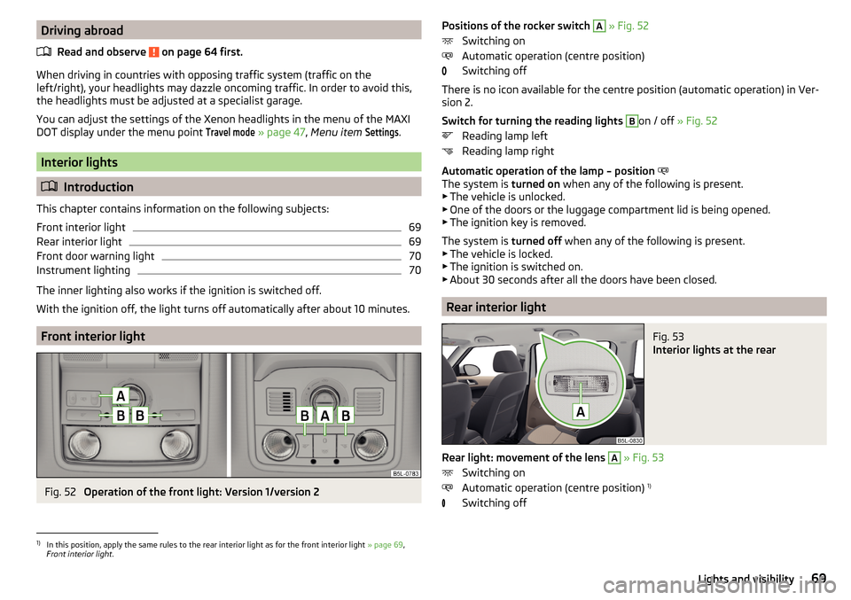
Interior lights
Introduction
This chapter contains information on the following subjects:
Front interior light
69
Rear interior light
69
Front door warning light
70
Instrument lighting
70
The inner lighting also works if the ignition is switched off.
With the ignition off, the light turns off automatically after about 10 minutes.
Front interior light
Fig. 52
Operation of the front light: Version 1/version 2
Positions of the rocker switch A » Fig. 52
Switching on
Automatic operation (centre position)
Switching off
There is no icon available for the centre position (automatic operation) in Ver-
sion 2.
Switch for turning the reading lights B
on / off » Fig. 52
Reading lamp left
Reading lamp right
Automatic operation of the lamp – position
The system is turned on when any of the following is present.
▶ The vehicle is unlocked.
▶ One of the doors or the luggage compartment lid is being opened.
▶ The ignition key is removed.
The system is turned off when any of the following is present.
▶ The vehicle is locked.
▶ The ignition is switched on.
▶ About 30 seconds after all the doors have been closed.
Rear interior light
Fig. 53
Interior lights at the rear
Rear light: movement of the lens
A
» Fig. 53
Switching on
Automatic operation (centre position) 1)
Switching off
1)
In this position, apply the same rules to the rear interior light as for the front interior light » page 69,
Front interior light .
69Lights and visibility
Page 76 of 232
The mirror dimming is controlled by the light incident on the sensors on the
front and back of the mirror.
When the interior lights are switched on or the reverse gear is engaged, the
mirror moves back into the basic position (not dimmed).
Do not attach external devices (e.g. navigation systems) on to the windscreen or in the vicinity of the interior mirror »
.
WARNING■
The illuminated display of an external navigation device can lead to op-
erational faults to the automatic dimming interior mirror – risk of accident.■
Automatic mirror dimming only operates correctly if the light striking the
sensor is not affected by other objects.
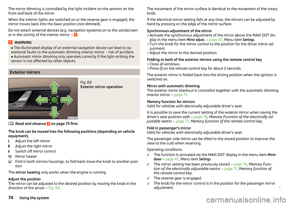
Exterior mirrors
Fig. 60
Exterior mirror operation
Read and observe on page 73 first.
The knob can be moved into the following positions (depending on vehicle
equipment).
Adjust the left mirror
Adjust the right mirror
Switch off mirror control
Mirror heater
Fold in both mirrors housings, to fold back move the knob to another posi-
tion
The mirror heating only works when the engine is running.
Adjust the position
The mirror can be adjusted to the desired position by moving the knob in the direction of the arrow » Fig. 60.
The movement of the mirror surface is identical to the movement of the rotary
knob.
If the electrical mirror setting fails at any time, the mirrors can be adjusted by
hand by pressing on the edge of the mirror surface.
Synchronous adjustment of the mirror›
Activate the synchronous adjustment of the mirror above the MAXI DOT dis- play in the menu item
Mirror adjust.
» page 47 , Menu item
Settings
.
›
Turn the knob for the mirror control to the position for the driver mirror ad-
justment.
›
Adjust the mirror to the desired position.
Folding-in both of the exterior mirrors using the remote control key
›
Close all windows.
›
Press on the remote control key for about 2 seconds.
The exterior mirror is folded back into the driving position when the ignition is
switched on.
Mirror with automatic dimming
The exterior mirror blackout is controlled together with the automatic dimming
interior mirror » page 73.
Memory function for mirrors
Valid for vehicles with electrically adjustable driver's seat.
It is possible to save the current setting of the exterior mirror when saving the
driver's seat position with » page 76, Memory Function of the electrically ad-
justable seat or » page 77 , Memory function of the remote control key .
Fold in passenger's mirror
Valid for vehicles with electrically adjustable driver's seat.
The passenger-side mirror can be tilted to the stored position to improve the
view to the curb when reversing.
Operating conditions. The function is activated via the MAXI DOT display in the menu item
Mirrordown
» page 47 , Menu item
Settings
.
The mirror setting has been previously stored » page 76, Memory Func-
tion of the electrically adjustable seat or » page 77 , Memory function of
the remote control key .
The reverse gear is engaged.
The knob for the mirror control is in the position for the passenger mirror
adjustment.
74Using the system
Page 77 of 232
The mirror returns to its initial position after the rotary knob is put into anoth-
er position or if the speed is more than 15 km/h.WARNINGDo not touch the exterior mirror surfaces, if the exterior mirror heating is
switched on - hazard of burning.
CAUTION
■ Never adjust retractable exterior mirrors by hand - risk of damaging the
electric mirror actuator!■
When the mirror is swung by external influences (due to impact during ma-
noeuvring, for example), then first fold-in the mirror by turning the knob and
wait for a loud clapping noise.
Seats and head restraints
Front seat
Introduction
This chapter contains information on the following subjects:
Manually adjusting seats
76
Electrical adjustment
76
Memory Function of the electrically adjustable seat
76
Memory function of the remote control key
77WARNING■ Only adjust the driver's seat when the vehicle is stationary – risk of acci-
dent!■
Caution when adjusting the seat! You may suffer injuries or bruises as a
result of adjusting the seat without paying proper attention.
■
The electric front seat adjustment is functional even with the ignition off.
Therefore, when leaving the vehicle, never leave people who are not com-
pletely independent, such as children, unattended in the vehicle - there is a
danger of injury!
■
Do not carry any objects on the front passenger seat except objects de-
signed for this purpose (e.g. child seats) – risk of accident!
Note
■ After a certain time, play can develop within the adjustment mechanism of
the backrest angle.■
For safety reasons, it is not possible to store the seat position in the electric
seat memory and remote control key memory if the inclination angle of the
seat backrest is more than 102° in relation to the seat cushion.
■
Each time you store the position of the electrically adjustable driver's seat
and exterior mirrors, the existing setting is deleted.
75Seats and head restraints
Page 79 of 232
›Within 10 seconds after pressing the
button, press the desired memory
button B.
An acknowledgement sound confirms the storage.
Saving front passenger mirror settings when reversing
Above the MAXI DOT display in the
Mirror down
menu item, the lowering func-
tion for the mirror on the passenger side must be enabled for reversing
» page 47 , Menu item
Settings
.
›
Switch on the ignition.
›
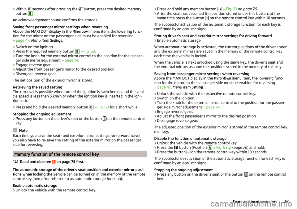
Press the required memory button
B
» Fig. 63 .
›
Turn the knob for the external mirror control to the position for the passen-
ger side mirror adjustment » page 74.
›
Engage reverse gear.
›
Adjust the front passenger's mirror to the desired position.
›
Disengage reverse gear.
The set position of the exterior mirror is stored.
Retrieving the saved setting
The retrieval is possible when turned the ignition is switched on and the vehi-
cle speed is less than 5 km/h or when the ignition key is inserted in the igni-
tion lock.
›
Press and hold the desired memory button
B
» Fig. 63 for a short while.
Stopping the ongoing adjustment
›
Press any button on the driver's seat or the button on the remote control
key.
Note
Each time you save the seat- and exterior mirror settings for forward travel
you also have to re-save the setting of the exterior mirror on the passenger
side for reversing.
Memory function of the remote control key
Read and observe
on page 75 first.
The automatic storage of the driver's seat position and exterior mirror posi-tions when locking the vehicle can be turned on in the memory of the remote
control key (hereafter referred to as automatic storage function).
Enable automatic storage
›
Unlock the vehicle with the remote control key.
› Press and hold any memory button B
» Fig. 63 on page 76 .›After the seat has assumed the position stored under this button, at the
same time press the button on the remote control key within 10 seconds.
The successful activation of the automatic storage function for each key is
confirmed by an acoustic signal.
Storing driver's seat and exterior mirror settings for driving forward
›
Enable automatic storage.
When automatic storage is activated, the current positions of the driver's seat
and the external mirrors are saved in the memory of the remote control key
each time the vehicle is locked.
When the vehicle is next unlocked using the same key, the driver's seat and
the external mirrors assume the positions stored in the memory of this key.
Saving front passenger mirror settings when reversing
Above the MAXI DOT display in the
Mirror down
menu item, the lowering func-
tion for the mirror on the passenger side must be enabled for reversing
» page 47 , Menu item
Settings
.
›
Unlock the vehicle with the respective remote control key.
›
Switch on the ignition.
›
Turn the knob for the external mirror control to the position for the passen-
ger side mirror adjustment » page 74.
›
Engage reverse gear.
›
Adjust the front passenger's mirror to the desired position.
›
Disengage reverse gear.
The adjusted position of the exterior mirror is stored in the remote control key
memory.
Disable the function of automatic storage
›
Unlock the vehicle with the remote control key.
›
Press the button (Position
A
» Fig. 63 on page 76 ) and hold.
›
Press the button on the remote control key within 10 seconds.
The successful deactivation of the automatic storage function for each key is confirmed by an acoustic signal.
Stopping the ongoing adjustment
›
Press any button on the driver's seat or the button on the remote control
key.
77Seats and head restraints
Page 91 of 232
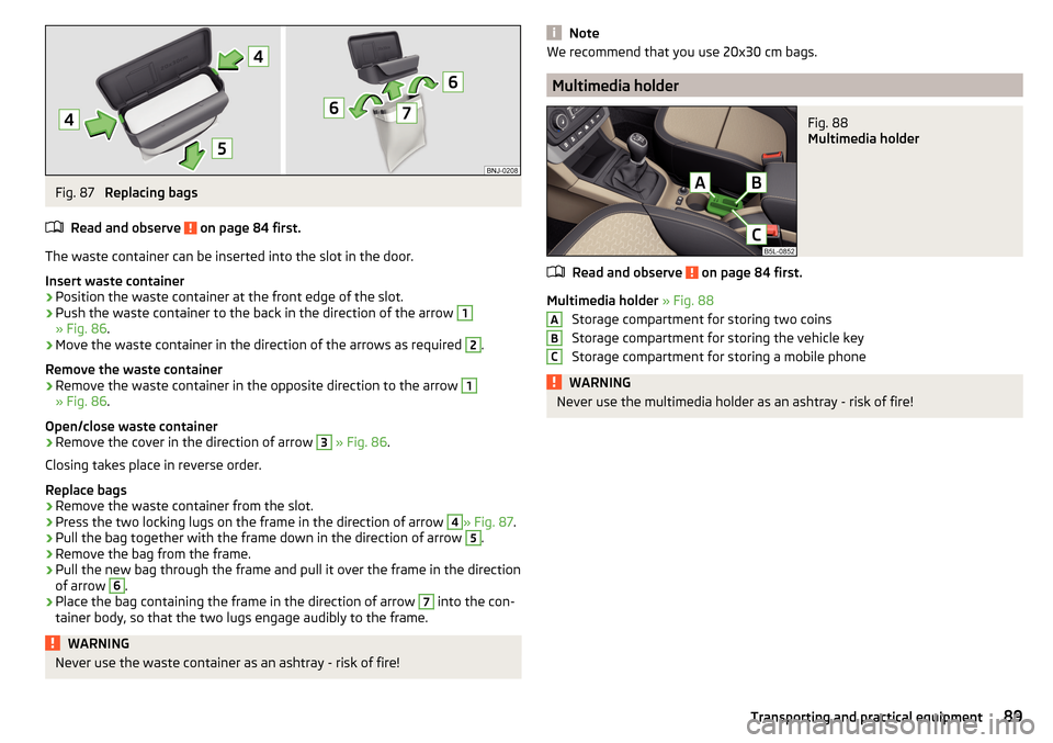
Fig. 87
Replacing bags
Read and observe
on page 84 first.
The waste container can be inserted into the slot in the door.
Insert waste container
›
Position the waste container at the front edge of the slot.
›
Push the waste container to the back in the direction of the arrow
1
» Fig. 86 .
›
Move the waste container in the direction of the arrows as required
2
.
Remove the waste container
›
Remove the waste container in the opposite direction to the arrow
1
» Fig. 86 .
Open/close waste container
›
Remove the cover in the direction of arrow
3
» Fig. 86 .
Closing takes place in reverse order.
Replace bags
›
Remove the waste container from the slot.
›
Press the two locking lugs on the frame in the direction of arrow
4
» Fig. 87 .
›
Pull the bag together with the frame down in the direction of arrow
5
.
›
Remove the bag from the frame.
›
Pull the new bag through the frame and pull it over the frame in the direction
of arrow
6
.
›
Place the bag containing the frame in the direction of arrow
7
into the con-
tainer body, so that the two lugs engage audibly to the frame.
WARNINGNever use the waste container as an ashtray - risk of fire!NoteWe recommend that you use 20x30 cm bags.
Multimedia holder
Fig. 88
Multimedia holder
Read and observe on page 84 first.
Multimedia holder » Fig. 88
Storage compartment for storing two coins
Storage compartment for storing the vehicle key
Storage compartment for storing a mobile phone
WARNINGNever use the multimedia holder as an ashtray - risk of fire!ABC89Transporting and practical equipment
Page 105 of 232
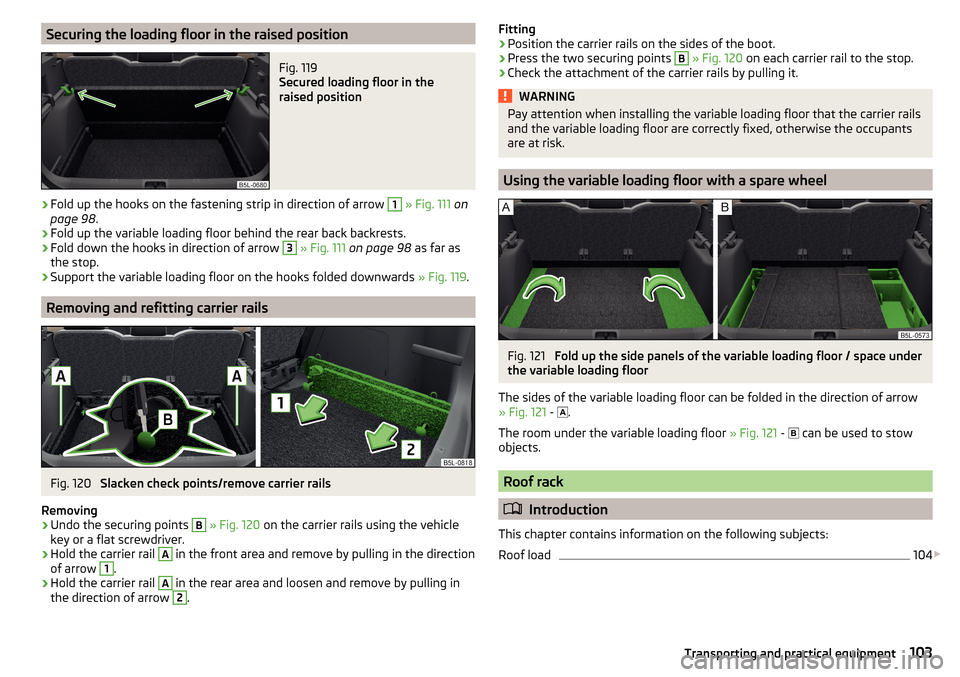
Securing the loading floor in the raised positionFig. 119
Secured loading floor in the
raised position
›
Fold up the hooks on the fastening strip in direction of arrow
1
» Fig. 111 on
page 98 .
›
Fold up the variable loading floor behind the rear back backrests.
›
Fold down the hooks in direction of arrow
3
» Fig. 111 on page 98 as far as
the stop.
›
Support the variable loading floor on the hooks folded downwards » Fig. 119.
Removing and refitting carrier rails
Fig. 120
Slacken check points/remove carrier rails
Removing
›
Undo the securing points
B
» Fig. 120 on the carrier rails using the vehicle
key or a flat screwdriver.
›
Hold the carrier rail
A
in the front area and remove by pulling in the direction
of arrow
1
.
›
Hold the carrier rail
A
in the rear area and loosen and remove by pulling in
the direction of arrow
2
.
Fitting›Position the carrier rails on the sides of the boot.›
Press the two securing points
B
» Fig. 120 on each carrier rail to the stop.
›
Check the attachment of the carrier rails by pulling it.
WARNINGPay attention when installing the variable loading floor that the carrier rails
and the variable loading floor are correctly fixed, otherwise the occupants
are at risk.
Using the variable loading floor with a spare wheel
Fig. 121
Fold up the side panels of the variable loading floor / space under
the variable loading floor
The sides of the variable loading floor can be folded in the direction of arrow
» Fig. 121 -
.
The room under the variable loading floor » Fig. 121 -
can be used to stow
objects.
Roof rack
Introduction
This chapter contains information on the following subjects:
Roof load
104
103Transporting and practical equipment