key SKODA YETI 2015 1.G / 5L Workshop Manual
[x] Cancel search | Manufacturer: SKODA, Model Year: 2015, Model line: YETI, Model: SKODA YETI 2015 1.G / 5LPages: 232, PDF Size: 30.84 MB
Page 167 of 232
›Fill the AdBlue ®
through the filler A according to the instructions on the re-
fill bottle » .›
After filling AdBlue ®
put the tank cap on the fuel filler neck and turn in the
opposite direction of the arrow
4
until it reaches the stop.
›
Close the filler cap in the opposite direction to the arrow
3
.
›
Store the box for the vehicle tools in the same place.
›
Fold back the floor in the luggage compartment.
Before driving
›
After filling AdBlue ®
only switch on the ignition and leave it on for at least 30
s, so that the refilling can be recognized by the system.
Only then start the engine.
CAUTION
Make sure that when refilling AdBlue ®
the interior of the vehicle is not splash-
ed - there is a risk of damage to the interior.
Note
The working life of the AdBlue ®
solution is 4 years. After this time, the solution
must be replaced by a specialist garage.
Engine compartment
Introduction
This chapter contains information on the following subjects:
Opening and closing the bonnet
166
Engine compartment overview
167
Radiator fan
167
Windscreen washer system
167WARNINGInjuries or scolding or risks of accident or fire may occur when working in
the engine compartment. For this reason, it is essential to comply with the
warning instructions outlined below and with the general applicable safety
rules. The engine compartment of your car is a hazardous area!WARNINGInstructions before beginning work in the engine compartment■Turn off the engine and remove the ignition key.■
Firmly apply the handbrake.
■
For vehicles with manual transmission the lever into the neutral position.
■
On vehicles with automatic transmission, shift the selector lever into the
P position.
■
Allow the engine to cool.
■
Never open the bonnet if you can see steam or coolant escaping from the
engine compartment – risk of scalding! Wait until no more steam or coolant
is escaping.
WARNINGInformation for working in the engine room■Keep all people, especially children, away from the engine compartment.■
Never touch the radiator fan. The fan might suddenly start running!
■
Do not touch any hot engine parts – risk of burns!
WARNINGInformation for working in the engine compartment with the engine run-
ning■
Pay particular attention to moving engine parts, e.g. V-ribbed belt, gener-
ator, radiator fan - danger to life!
■
Never touch the electric wiring on the ignition system.
■
Avoid short circuits in the electrical system, particularly on the vehicle's
battery.
■
Always make sure that no jewellery, loose clothing or long hair can get
caught in rotating engine parts – risk to life! Always remove any jewellery,
tie back long hair and wear tight fitting clothing before completing any
work.
WARNINGInformation for working on the fuel system or the electrical system■Always disconnect the vehicle battery from the electrical system.■
Do not smoke.
■
Never work near open flames.
■
Always have a functioning fire extinguisher nearby.
165Inspecting and replenishing
Page 184 of 232
The fire extinguisher is attached by two straps in a holder underneath the driv-
er's seat.
Removing/attaching›
Loosen the two straps by pulling the buckles in the direction of the arrow
» Fig. 178 .
›
Remove the fire extinguisher.
›
Secure the fire extinguisher by placing it back into the holder and fastening
with straps.
Please read the instructions which are attached to the fire extinguisher.
Pay attention to the expiration date of the fire extinguisher. If the fire extin-
guisher is used after the expiration date, its proper function is not assured.
WARNINGThe fire extinguisher must always be secured safely so that they do not
come loose when making an emergency braking or in a vehicle collision
which could cause injuries to occupants.
Note
The fire extinguisher is part of the scope of delivery in certain countries only.
Vehicle tool kit
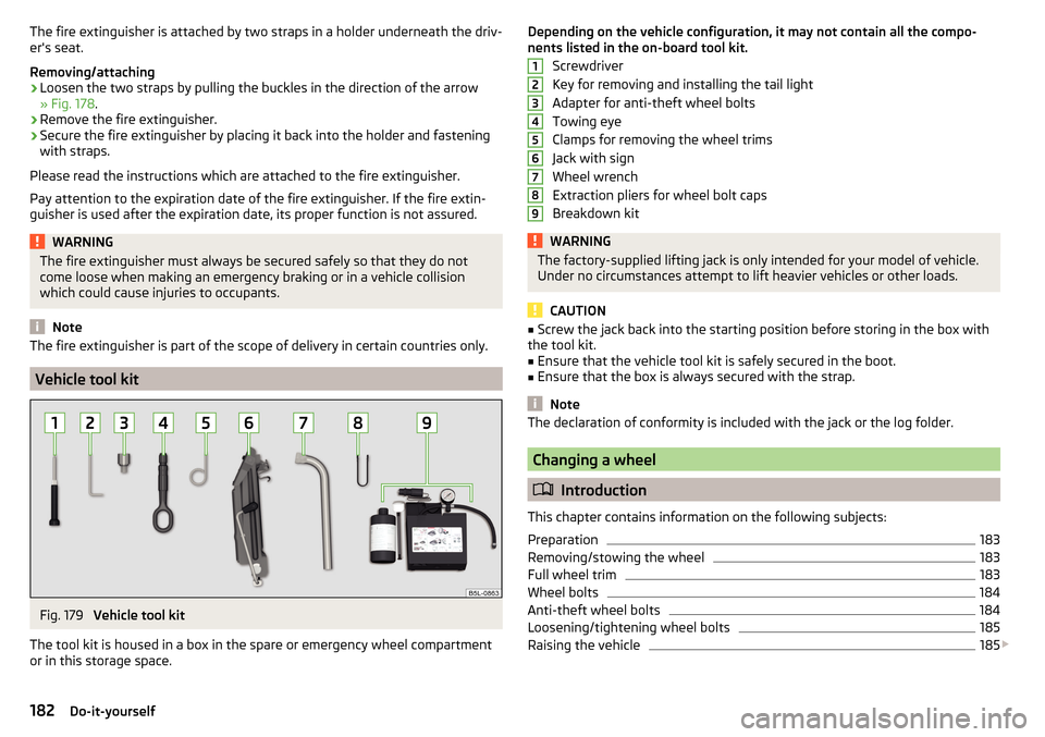
Fig. 179
Vehicle tool kit
The tool kit is housed in a box in the spare or emergency wheel compartment
or in this storage space.
Depending on the vehicle configuration, it may not contain all the compo-
nents listed in the on-board tool kit.
Screwdriver
Key for removing and installing the tail light
Adapter for anti-theft wheel bolts
Towing eye
Clamps for removing the wheel trims
Jack with sign
Wheel wrench
Extraction pliers for wheel bolt caps
Breakdown kitWARNINGThe factory-supplied lifting jack is only intended for your model of vehicle.
Under no circumstances attempt to lift heavier vehicles or other loads.
CAUTION
■ Screw the jack back into the starting position before storing in the box with
the tool kit.■
Ensure that the vehicle tool kit is safely secured in the boot.
■
Ensure that the box is always secured with the strap.
Note
The declaration of conformity is included with the jack or the log folder.
Changing a wheel
Introduction
This chapter contains information on the following subjects:
Preparation
183
Removing/stowing the wheel
183
Full wheel trim
183
Wheel bolts
184
Anti-theft wheel bolts
184
Loosening/tightening wheel bolts
185
Raising the vehicle
185
123456789182Do-it-yourself
Page 194 of 232
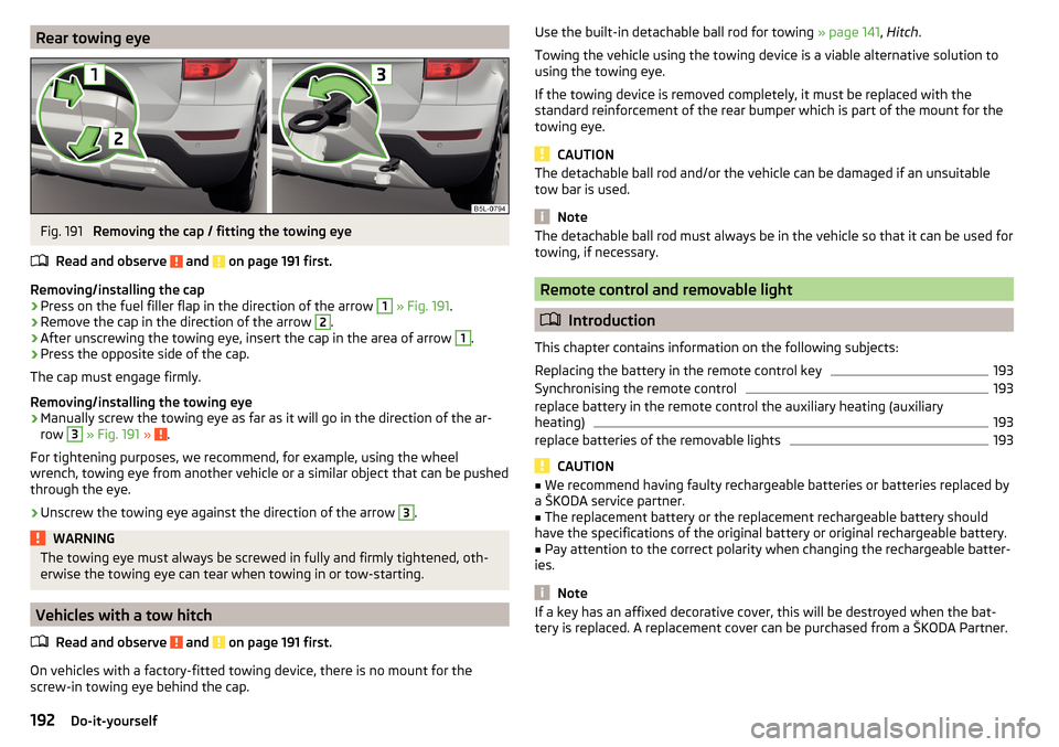
Rear towing eyeFig. 191
Removing the cap / fitting the towing eye
Read and observe
and on page 191 first.
Removing/installing the cap
›
Press on the fuel filler flap in the direction of the arrow
1
» Fig. 191 .
›
Remove the cap in the direction of the arrow
2
.
›
After unscrewing the towing eye, insert the cap in the area of arrow
1
.
›
Press the opposite side of the cap.
The cap must engage firmly.
Removing/installing the towing eye
›
Manually screw the towing eye as far as it will go in the direction of the ar-
row
3
» Fig. 191 » .
For tightening purposes, we recommend, for example, using the wheel
wrench, towing eye from another vehicle or a similar object that can be pushed
through the eye.
›
Unscrew the towing eye against the direction of the arrow
3
.
WARNINGThe towing eye must always be screwed in fully and firmly tightened, oth-
erwise the towing eye can tear when towing in or tow-starting.
Vehicles with a tow hitch
Read and observe
and on page 191 first.
On vehicles with a factory-fitted towing device, there is no mount for the
screw-in towing eye behind the cap.
Use the built-in detachable ball rod for towing » page 141, Hitch .
Towing the vehicle using the towing device is a viable alternative solution to
using the towing eye.
If the towing device is removed completely, it must be replaced with the
standard reinforcement of the rear bumper which is part of the mount for the
towing eye.
CAUTION
The detachable ball rod and/or the vehicle can be damaged if an unsuitable
tow bar is used.
Note
The detachable ball rod must always be in the vehicle so that it can be used for
towing, if necessary.
Remote control and removable light
Introduction
This chapter contains information on the following subjects:
Replacing the battery in the remote control key
193
Synchronising the remote control
193
replace battery in the remote control the auxiliary heating (auxiliary
heating)
193
replace batteries of the removable lights
193
CAUTION
■ We recommend having faulty rechargeable batteries or batteries replaced by
a ŠKODA service partner.■
The replacement battery or the replacement rechargeable battery should
have the specifications of the original battery or original rechargeable battery.
■
Pay attention to the correct polarity when changing the rechargeable batter-
ies.
Note
If a key has an affixed decorative cover, this will be destroyed when the bat-
tery is replaced. A replacement cover can be purchased from a ŠKODA Partner.192Do-it-yourself
Page 195 of 232

Replacing the battery in the remote control keyFig. 192
Remove cover/take out battery
Read and observe
on page 192 first.
The battery change is carried out as follows.
›
Flip out the key.
›
Press off the battery cover
A
» Fig. 192 with your thumb or using a flat
screwdriver in the region of the arrows
1
.
›
Remove the discharged battery from the key by pressing the battery down in
the region of the arrow
2
.
›
Insert the new battery.
›
Insert the battery cover
A
and press it down until it clicks audibly into place.
The key has to be synchronised if the vehicle cannot be unlocked or locked
with the remote control key after replacing the battery » page 193.
Synchronising the remote control
Read and observe
on page 192 first.
If the vehicle does not unlock when pressing the remote control, the key may
not be synchronised. This can occur when the buttons on the remote control
key are actuated a number of times outside of the operative range of the
equipment or the battery in the remote control key has been replaced.
Synchronise the key as follows.
›
Press any button on the remote control key.
›
Unlock the door with the key in the lock cylinder within 1 minute of pressing the button.
replace battery in the remote control the auxiliary heating
(auxiliary heating)Fig. 193
Radio remote control: Battery
cover
Read and observe on page 192 first.
The battery is located under a cover on the back of the radio remote control » Fig. 193 .
›
Insert a flat, blunt object, such as a coin, into the gap of the battery cover.
›
Turn the cover against the direction of the arrow up to the mark to open the
cover.
›
Replace the battery.
›
Return the battery cover.
›
Turn the cover in the direction of the arrow up to the initial marking, engage.
replace batteries of the removable lights
Fig. 194
Taking out the lamp
Read and observe on page 192 first.
The battery change is carried out as follows.
›
Take out the light in the direction of arrow » Fig. 194.
193Emergency equipment and self-help
Page 196 of 232

›Lever off the cover for the rechargeable batteries with a narrow and pointed
object from the area of the lock clips A.›
Take out the faulty rechargeable batteries from the lamp.
›
Insert the new rechargeable batteries.
›
Insert the cover for the rechargeable batteries and press it down until it
clicks into place.
CAUTION
If an incorrect rechargeable battery is used or a non-rechargeable battery,
there is a risk of damaging the lamp and the vehicle's electrical system.
Emergency unlocking/locking
Introduction
This chapter contains information on the following subjects:
Unlocking/locking the driver's door
194
Locking the door without a locking cylinder
194
Unlock the boot lid
194
Selector lever-emergency unlocking
195
Unlocking/locking the driver's door
Fig. 195
Handle on the driver's door: cov-
ered key cylinder
The driver's door can be unlocked or locked in an emergency.
›
Pull on the door handle and hold in place.
›
Insert the vehicle key into the slot on the bottom of the cover in the arrow
area » Fig. 195 .
›
Fold the cover upwards.
›
Release the door handle.
›
Insert the vehicle key bit into the lock cylinder and unlock or lock the vehicle.
Pull on the door handle and replace the cover in its original location.
CAUTION
Make sure you do not damage the paint when performing an emergency lock-
ing/unlocking.
Locking the door without a locking cylinder
Fig. 196
Emergency locking: Left/right rear door
An emergency locking mechanism is located on the face side of the doors
which have no locking cylinder, it is only visible after opening the door.
›
Remove the cover
A
» Fig. 196 .
›
Insert the vehicle key into the slot and turn in the direction of the arrow
(sprung position).
›
Replace the cover
A
.
Unlock the boot lid
Fig. 197
Unlocking the boot lid
The boot lid can be unlocked manually.
›
Fold the rear seat backrest forward » page 80.
194Do-it-yourself
Page 203 of 232
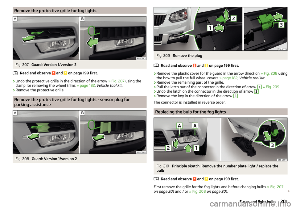
Remove the protective grille for fog lightsFig. 207
Guard: Version 1/version 2
Read and observe
and on page 199 first.
›
Undo the protective grille in the direction of the arrow » Fig. 207 using the
clamp for removing the wheel trims » page 182, Vehicle tool kit .
›
Remove the protective grille.
Remove the protective grille for fog lights - sensor plug for
parking assistance
Fig. 208
Guard: Version 1/version 2
Fig. 209
Remove the plug
Read and observe
and on page 199 first.
›
Remove the plastic cover for the guard in the arrow direction » Fig. 208 using
the bow to pull the full wheel covers » page 182, Vehicle tool kit .
›
Remove the remaining part of the grille.
›
Pull the latch out of the connector in the direction of arrow
1
» Fig. 209 .
›
Undo the latch on the connector in the direction of arrow
2
.
›
Remove the key in the direction of the arrow
3
.
The connector is installed in reverse order.
Replacing the bulb for the fog lights
Fig. 210
Principle sketch: Remove the number plate light / replace the
bulb
Read and observe
and on page 199 first.
First remove the grille for the fog lights and before changing bulbs » Fig. 207
on page 201 and / or » Fig. 208 on page 201 .
201Fuses and light bulbs
Page 216 of 232
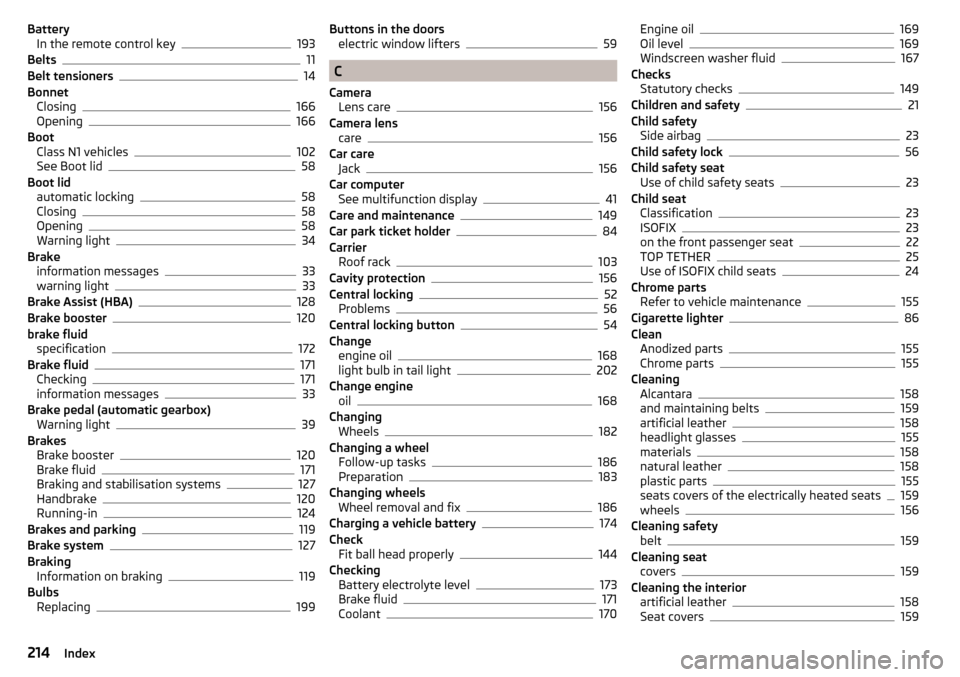
BatteryIn the remote control key193
Belts11
Belt tensioners14
Bonnet Closing
166
Opening166
Boot Class N1 vehicles
102
See Boot lid58
Boot lid automatic locking
58
Closing58
Opening58
Warning light34
Brake information messages
33
warning light33
Brake Assist (HBA)128
Brake booster120
brake fluid specification
172
Brake fluid171
Checking171
information messages33
Brake pedal (automatic gearbox) Warning light
39
Brakes Brake booster
120
Brake fluid171
Braking and stabilisation systems127
Handbrake120
Running-in124
Brakes and parking119
Brake system127
Braking Information on braking
119
Bulbs Replacing
199
Buttons in the doorselectric window lifters59
C
Camera Lens care
156
Camera lens care
156
Car care Jack
156
Car computer See multifunction display
41
Care and maintenance149
Car park ticket holder84
Carrier Roof rack
103
Cavity protection156
Central locking52
Problems56
Central locking button54
Change engine oil
168
light bulb in tail light202
Change engine oil
168
Changing Wheels
182
Changing a wheel Follow-up tasks
186
Preparation183
Changing wheels Wheel removal and fix
186
Charging a vehicle battery174
Check Fit ball head properly
144
Checking Battery electrolyte level
173
Brake fluid171
Coolant170
Engine oil169
Oil level169
Windscreen washer fluid167
Checks Statutory checks
149
Children and safety21
Child safety Side airbag
23
Child safety lock56
Child safety seat Use of child safety seats
23
Child seat Classification
23
ISOFIX23
on the front passenger seat22
TOP TETHER25
Use of ISOFIX child seats24
Chrome parts Refer to vehicle maintenance
155
Cigarette lighter86
Clean Anodized parts
155
Chrome parts155
Cleaning Alcantara
158
and maintaining belts159
artificial leather158
headlight glasses155
materials158
natural leather158
plastic parts155
seats covers of the electrically heated seats159
wheels156
Cleaning safety belt
159
Cleaning seat covers
159
Cleaning the interior artificial leather
158
Seat covers159
214Index
Page 219 of 232
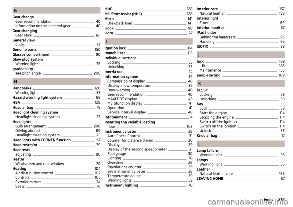
G
Gear change Gear recommendation
40
Information on the selected gear40
Gear changing Gear stick
121
General view Cockpit
27
Genuine parts150
Glasses compartment90
Glow plug system Warning light
36
gradeability see pitch angle
208
H
Handbrake
120
Warning light33
Hazard warning light system68
HBA128
Head airbag19
Headlight cleaning system Headlight cleaning system
73
Headlights Bulb arrangement
200
Driving abroad69
Headlight cleaning system73
Headlights with CORNER function67
Head restraint79
Headrests adjusting
80
Heater Windscreen and rear window
70
Heating104
Air distribution control107
Controls105
Exterior mirrors74
Seats78
HHC128
Hill Start Assist (HHC)128
Hitch141
Drawback load141
Hook98
Horn27
I
Ignition lock
114
Immobilizer113
Individual settings Locking
55
Unlocking55
Inertia reel14
Information system39
Compass point display48
Display a low temperature39
Door warning40
Gear recommendation40
MAXI DOT display43
Multifunction display41
Operation41
Service interval display48
Infotainment4
Inserting the variable loading floor
102
Instrument cluster28
Auto Check Control31
Counter for distance driven30
Display29
Display of the second speedometer31
Fuel gauge30
Lighting70
Overview28
Revolutions counter29
see instrument cluster28
Temperature gauge29
Warning lights32
Instrument lighting70
Interior care157
Natural leather158
Interior light Front
69
Interior monitor57
iPad holder Behind the headrests
95
Handling95
ISOFIX23
J
Jack
182
- fit185
Maintenance156
Jump-starting189
K
KESSY Locking
53
Unlocking53
Key Lock
53
Start the engine114
Stopping the engine114
Switch off the ignition114
Switch on the ignition114
Unlock53
Knee airbag17
L
Lamp failure Warning light
36
Lamps Warning light
36
Leather Natural leather care
158
LEAVING HOME67
217Index
Page 220 of 232
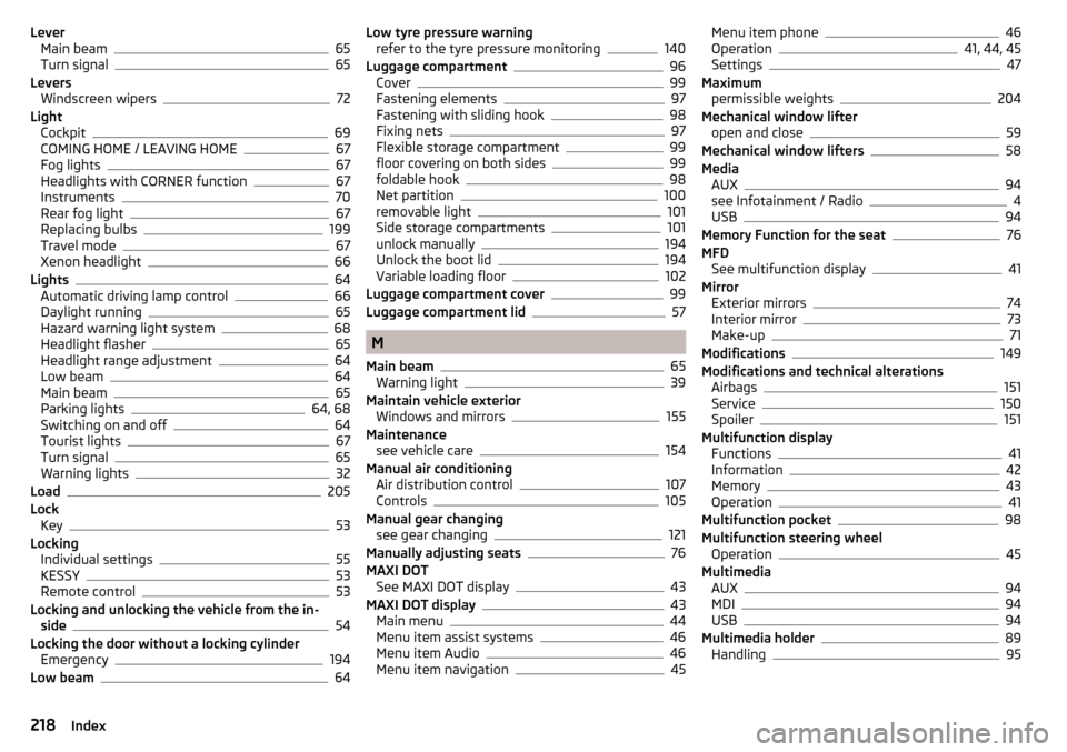
LeverMain beam65
Turn signal65
Levers Windscreen wipers
72
Light Cockpit
69
COMING HOME / LEAVING HOME67
Fog lights67
Headlights with CORNER function67
Instruments70
Rear fog light67
Replacing bulbs199
Travel mode67
Xenon headlight66
Lights64
Automatic driving lamp control66
Daylight running65
Hazard warning light system68
Headlight flasher65
Headlight range adjustment64
Low beam64
Main beam65
Parking lights64, 68
Switching on and off64
Tourist lights67
Turn signal65
Warning lights32
Load205
Lock Key
53
Locking Individual settings
55
KESSY53
Remote control53
Locking and unlocking the vehicle from the in- side
54
Locking the door without a locking cylinder Emergency
194
Low beam64
Low tyre pressure warning refer to the tyre pressure monitoring140
Luggage compartment96
Cover99
Fastening elements97
Fastening with sliding hook98
Fixing nets97
Flexible storage compartment99
floor covering on both sides99
foldable hook98
Net partition100
removable light101
Side storage compartments101
unlock manually194
Unlock the boot lid194
Variable loading floor102
Luggage compartment cover99
Luggage compartment lid57
M
Main beam
65
Warning light39
Maintain vehicle exterior Windows and mirrors
155
Maintenance see vehicle care
154
Manual air conditioning Air distribution control
107
Controls105
Manual gear changing see gear changing
121
Manually adjusting seats76
MAXI DOT See MAXI DOT display
43
MAXI DOT display43
Main menu44
Menu item assist systems46
Menu item Audio46
Menu item navigation45
Menu item phone46
Operation41, 44, 45
Settings47
Maximum permissible weights
204
Mechanical window lifter open and close
59
Mechanical window lifters58
Media AUX
94
see Infotainment / Radio4
USB94
Memory Function for the seat76
MFD See multifunction display
41
Mirror Exterior mirrors
74
Interior mirror73
Make-up71
Modifications149
Modifications and technical alterations Airbags
151
Service150
Spoiler151
Multifunction display Functions
41
Information42
Memory43
Operation41
Multifunction pocket98
Multifunction steering wheel Operation
45
Multimedia AUX
94
MDI94
USB94
Multimedia holder89
Handling95
218Index
Page 222 of 232
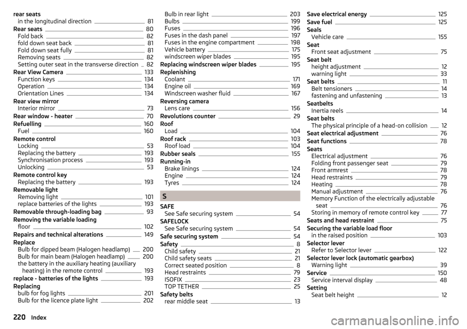
rear seatsin the longitudinal direction81
Rear seats80
Fold back82
fold down seat back81
Fold down seat fully81
Removing seats82
Setting outer seat in the transverse direction82
Rear View Camera133
Function keys134
Operation134
Orientation Lines134
Rear view mirror Interior mirror
73
Rear window - heater70
Refuelling160
Fuel160
Remote control Locking
53
Replacing the battery193
Synchronisation process193
Unlocking53
Remote control key Replacing the battery
193
Removable light Removing light
101
replace batteries of the lights193
Removable through-loading bag93
Removing the variable loading floor
102
Repairs and technical alterations149
Replace Bulb for dipped beam (Halogen headlamp)
200
Bulb for main beam (Halogen headlamp)200
the battery in the auxiliary heating (auxiliary heating) in the remote control
193
replace - batteries of the lights193
Replacing bulb for fog lights
201
Bulb for the licence plate light202
Bulb in rear light203
Bulbs199
Fuses196
Fuses in the dash panel197
Fuses in the engine compartment198
Vehicle battery175
windscreen wiper blades195
Replacing windscreen wiper blades195
Replenishing Coolant
171
Engine oil169
Windscreen washer fluid167
Reversing camera Lens care
156
Revolutions counter29
Roof Load
104
Roof rack103
Roof load104
Rubber seals155
Running-in Brake linings
124
Engine124
Tyres124
S
SAFE See Safe securing system
54
SAFELOCK See Safe securing system
54
Safe securing system54
Safety8
Child safety21
Child safety seats21
Correct seated position8
Head restraints79
ISOFIX23
TOP TETHER25
Safety belts rear middle seat
13
Save electrical energy125
Save fuel125
Seals Vehicle care
155
Seat Front seat adjustment
75
Seat belt height adjustment
12
warning light33
Seat belts11
Belt tensioners14
fastening and unfastening13
Seatbelts Inertia reels
14
Seat belts The physical principle of a head-on collision
12
Seat electrical adjustment76
Seat functions78
Seats Electrical adjustment
76
Folding front passenger seat79
Front armrest78
Head restraints79
Heating78
Manual adjustment76
Memory Function of the electrically adjustable seat
76
Storing in memory of remote control key77
Seats and head restraint75
Securing the variable load floor in the raised position
103
Selector lever Refer to Selector lever
122
Selector lever lock (automatic gearbox) Warning light
39
Service150
Service interval display48
Setting Seat belt height
12
220Index