front side SMART FORTWO COUPE ELECTRIC DRIVE 2014 Owner's Manual
[x] Cancel search | Manufacturer: SMART, Model Year: 2014, Model line: FORTWO COUPE ELECTRIC DRIVE, Model: SMART FORTWO COUPE ELECTRIC DRIVE 2014Pages: 222, PDF Size: 16.17 MB
Page 111 of 222
cle are indicated on the certification
label which can be found on the driver’s
door B‑pillar.
For more information, see “Loading the
vehicle” (Y page 133).
The handling characteristics of a fully
loaded vehicle depend greatly on the load
distribution. It is therefore recommended
to load the vehicle with the heaviest items
being placed towards the front of the vehi-
cle.
Please pay attention to and comply with the
following instructions when loading the
vehicle and transporting cargo:
R Always place items being carried
against seat backrests, and fasten them
as securely as possible.
R The heaviest portion of the cargo should
always be kept as low as possible against
seat backrests.
R Do not stack loads higher than the top
edge of the head restraints.
R Make sure no luggage/cargo items can get
above or next to the driver’s and/or
passenger seat into the passenger com-
partment.
R Make sure luggage/cargo is properly
secured.
R Always use, if so equipped, cargo net*
when transporting cargo.
Do not carry any unnecessary weight in the
vehicle. This increases vehicle weight,
which results in increased energy con-
sumption. Useful features
Sun visors
The sun visors protect you from sun glare
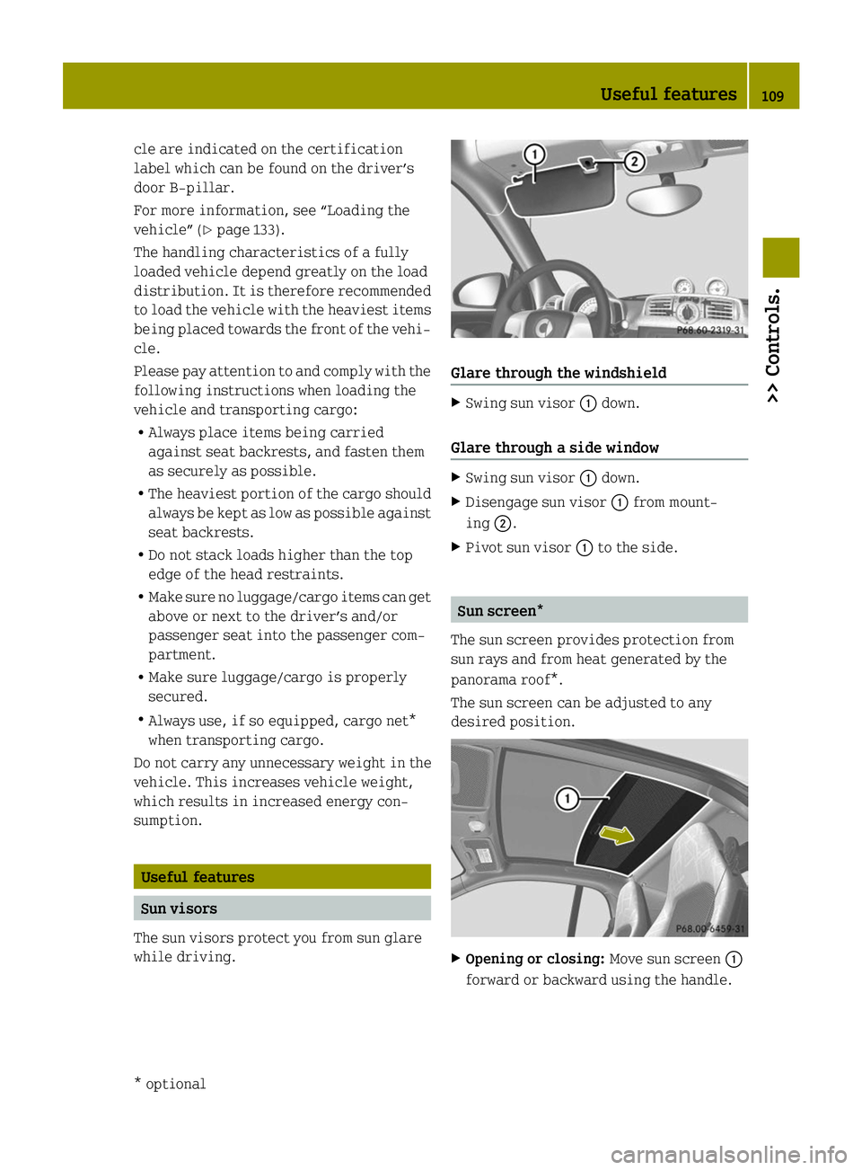
while driving. Glare through the windshield
X
Swing sun visor 0043down.
Glare through a side window X
Swing sun visor 0043down.
X Disengage sun visor 0043from mount-
ing 0044.
X Pivot sun visor 0043to the side. Sun screen*
The sun screen provides protection from
sun rays and from heat generated by the
panorama roof*.
The sun screen can be adjusted to any
desired position. X
Opening or closing: Move sun screen0043
forward or backward using the handle. Useful features
109>> Controls.
* optional Z
Page 125 of 222
X
Set the value of the charge current to
12 A and confirm.
X Press the encryption button on the pow-
erline adapter within three minutes.
When the powerline adapter shows a con-
nection, the connection process was suc-
cessful.
i Observe the separate operating
instructions of the powerline adapter.
i Contact an authorized electric drive
smart center if you have any questions.
X Next, set the value of the charge current
to the desired value once again.
As soon as the vehicle establishes an Inter-
net connection, you can also use the "Vehi-
cle Homepage" at home during the charging
process. Changes you have made via the
"Vehicle Homepage" are adopted after the
charging process is complete. This data
transmission ends after approximately
three days. Intelligent charging management
If you wish to charge economically and with
minimal damage to the battery, you must set
a departure time ( Ypage 90). This option
to optimize the charging process depends
on your electricity contract and the local
power supplier. Your vehicle detects this
option automatically. Depending on the
departure time which is set, the charging
process of the high-voltage battery may not
be started immediately or may be inter-
rupted during the process. Front compartment
Service flap
Remove the service flap to check the bat-
tery coolant level, windshield washer res-
ervoir level, and brake fluid level. Insert the service flap on the front of the
vehicle so that it does not get damaged or
dirty.
i
The service flap has a strap on the rear
side that ties it to the vehicle body. G
WARNING
Always turn the key to starter switch posi-
tion 0and remove the key from the starter
switch before opening the service flap.
If the windshield wipers should inadver-
tently be switched on, you could be ser-
iously injured by the wiper washer drive,
which is located just below the service
flap. G
WARNING
Make sure the service flap is locked while
driving. Otherwise, the service flap could
become detached and pose a hazard to you
or others.
! Check the fill levels at regular inter-
vals.
! Carefully remove ice, snow, and any
other deposits from the air intake
grilles above the service flap to ensure
air intake at all times.
X Park the vehicle on level ground.
X Switch off the ignition.
X Engage the parking brake. Front compartment
123>> Operation. Z
Page 126 of 222
Removing
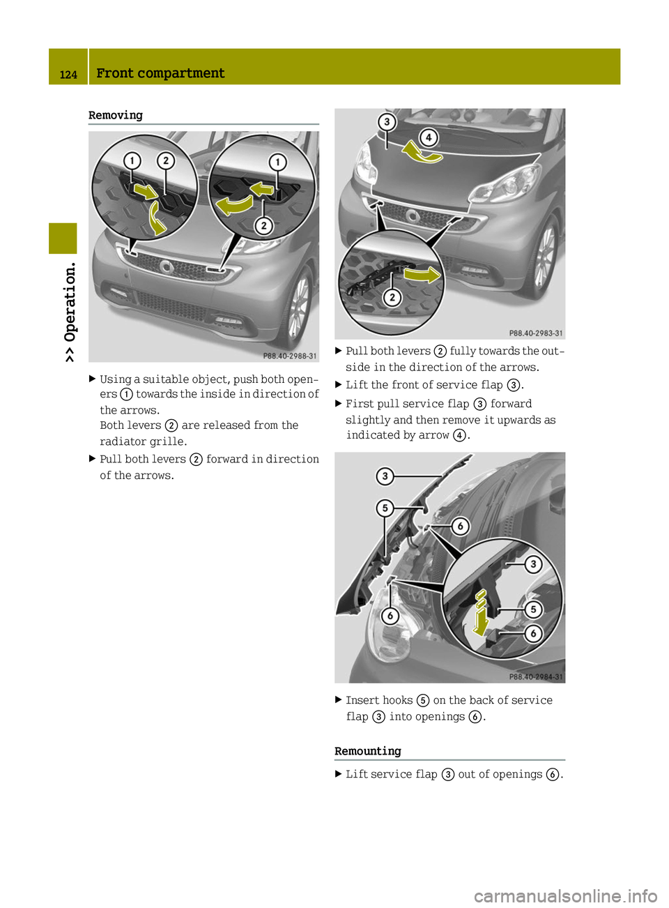
X
Using a suitable object, push both open-
ers 0043towards the inside in direction of
the arrows.
Both levers 0044are released from the
radiator grille.
X Pull both levers 0044forward in direction
of the arrows. X
Pull both levers 0044fully towards the out-
side in the direction of the arrows.
X Lift the front of service flap 0087.
X First pull service flap 0087forward
slightly and then remove it upwards as
indicated by arrow 0085. X
Insert hooks 0083on the back of service
flap 0087into openings 0084.
Remounting X
Lift service flap 0087out of openings 0084.124
Front compartment>> Operation.
Page 128 of 222
cooling period of at least 30 minutes. Oth-
erwise, you could be seriously burned if hot
coolant escapes.
The coolant is a mixture of water and anti-
corrosion/antifreeze. To check the coolant
level the vehicle must be parked on level
ground and the drive system must have
cooled down. For more information, see
„Coolants“ (Y page 219).
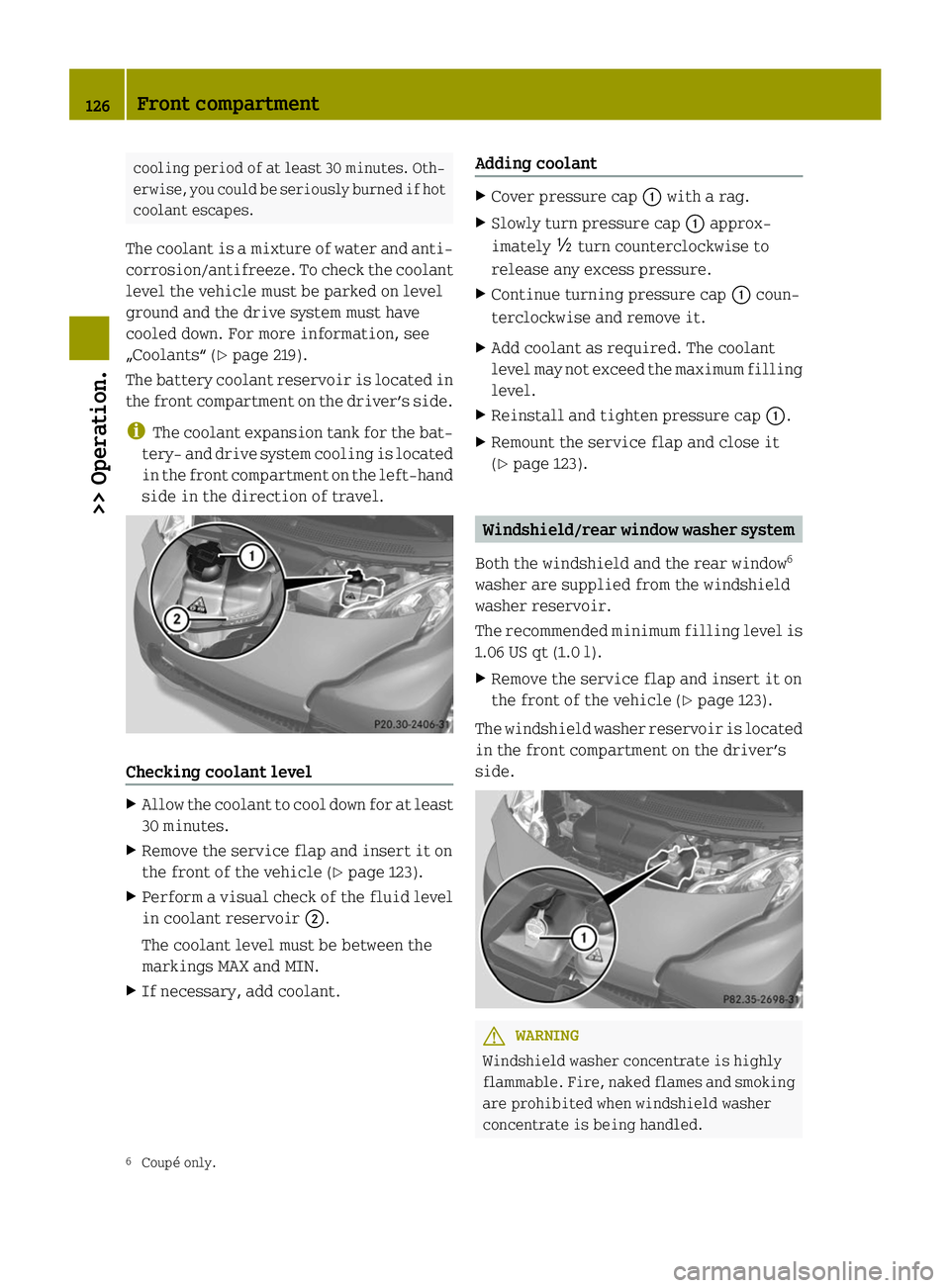
The battery coolant reservoir is located in
the front compartment on the driver’s side.
i The coolant expansion tank for the bat-
tery‑ and drive system cooling is located
in the front compartment on the left-hand
side in the direction of travel. Checking coolant level
X
Allow the coolant to cool down for at least
30 minutes.
X Remove the service flap and insert it on
the front of the vehicle (Y page 123).
X Perform a visual check of the fluid level
in coolant reservoir 0044.
The coolant level must be between the
markings MAX and MIN.
X If necessary, add coolant. Adding coolant X
Cover pressure cap 0043with a rag.
X Slowly turn pressure cap 0043approx-
imately 00C5turn counterclockwise to
release any excess pressure.
X Continue turning pressure cap 0043coun-
terclockwise and remove it.
X Add coolant as required. The coolant
level may not exceed the maximum filling
level.
X Reinstall and tighten pressure cap 0043.
X Remount the service flap and close it
(Y page 123). Windshield/rear window washer system
Both the windshield and the rear window 6
washer are supplied from the windshield
washer reservoir.
The recommended minimum filling level is
1.06 US qt (1.0 l).
X Remove the service flap and insert it on
the front of the vehicle (Y page 123).
The windshield washer reservoir is located
in the front compartment on the driver’s
side. G
WARNING
Windshield washer concentrate is highly
flammable. Fire, naked flames and smoking
are prohibited when windshield washer
concentrate is being handled.
6 Coupé only. 126
Front compartment>> Operation.
Page 129 of 222
X
Use a windshield washer concentrate
labeled for summer and water for tem-
peratures above freezing point.
X Use a windshield washer concentrate
labeled for winter and water for temper-
atures below freezing point.
! Always use a windshield washer concen-
trate labeled for winter where tempera-
tures may fall below freezing point.
Failure to do so could result in damage
to the washer system/reservoir.
X Premix the windshield washer fluid in a
suitable container.
Observe mixing ratios depending on the
outside temperature (Y page 218).
X Use the tab to pull cap 0043upwards.
X Refill the windshield washer reservoir.
X Push cap 0043onto the windshield washer
reservoir.
X Remount the service flap and close it
(Y page 123). Brake fluid
G
WARNING
During vehicle operation, the boiling
point of the brake fluid is continuously
reduced through the absorption of moisture
from the atmosphere. Under extremely
strenuous operating conditions, this mois-
ture content can lead to the formation of
bubbles in the system, thus reducing the
system’s efficiency.
Therefore, the brake fluid must be replaced
regularly. Refer to your vehicle’s Mainte-
nance Booklet for replacement interval.
The brake fluid level in the brake fluid
reservoir may be too low if the brake warn-
ing lamp in the instrument cluster comes
on (Y page 23) although the parking brake
is released.
! If you find that the brake fluid in the
brake fluid reservoir has fallen to the minimum mark or below, have the brake
system checked for brake pad thickness
and leaks immediately. Contact an
authorized electric drive smart center
immediately. Do not add brake fluid as
this will not solve the problem.
X Remove the service flap and insert it on
the front of the vehicle (Y page 123).
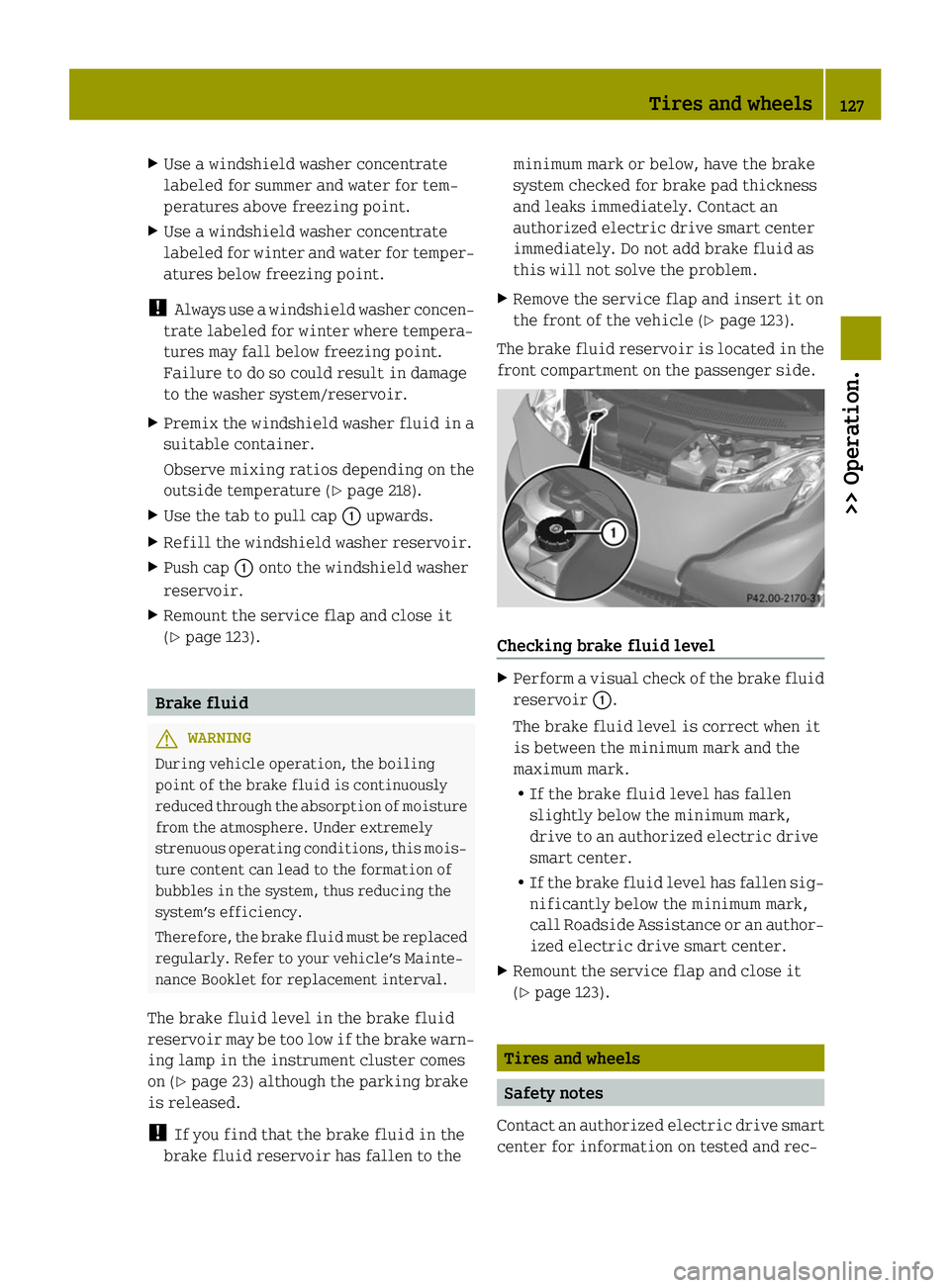
The brake fluid reservoir is located in the
front compartment on the passenger side. Checking brake fluid level
X
Perform a visual check of the brake fluid
reservoir 0043.
The brake fluid level is correct when it
is between the minimum mark and the
maximum mark.
R If the brake fluid level has fallen
slightly below the minimum mark,
drive to an authorized electric drive
smart center.
R If the brake fluid level has fallen sig-
nificantly below the minimum mark,
call Roadside Assistance or an author-
ized electric drive smart center.
X Remount the service flap and close it
(Y page 123). Tires and wheels
Safety notes
Contact an authorized electric drive smart
center for information on tested and rec- Tires and wheels
127>> Operation. Z
Page 141 of 222
The traction grades, from highest to low-
est, are AA, A, B, and C. Those grades rep-
resent the tire’s ability to stop on wet
pavement as measured under controlled
conditions on specified government test
surfaces of asphalt and concrete. A tire
marked C may have poor traction perform-
ance.
Temperature G
WARNING
The temperature grade for this tire is
established for a tire that is properly
inflated and not overloaded. Excessive
speed, underinflation, or excessive load-
ing, either separately or in combination,
can cause excessive heat build-up and pos-
sible tire failure.
The temperature grades are A (the highest),
B, and C, representing the tire’s resistance
to the generation of heat and its ability to
dissipate heat when tested under control-
led conditions on a specified indoor lab-
oratory test wheel. Sustained high temper-
ature can cause the material of the tire to
degenerate and reduce tire life, and
excessive temperature can lead to sudden
tire failure. The grade C corresponds to a
level of performance which all passenger
car tires must meet under the Federal Motor
Vehicle Safety Standard No. 109. Grades B
and A represent higher levels of perform-
ance on the laboratory test wheel than the
minimum required by law. Rotating tires
G
WARNING
Do not rotate front and rear wheels as they
have different dimensions, e.g. rim size,
wheel offset etc. Otherwise, the handling
can be affected and you could endanger
yourself and others. Thoroughly clean the mounting face of the
wheels and brake discs, i.e. the inner side
of the wheels/tires each time the wheels/
tires are changed. Check for and ensure
proper tire inflation pressure. G
WARNING
Have the tightening torque checked after
changing a wheel. Wheels could become
loose if not tightened with a torque of
81 lb‑ft (110 Nm).
Only use genuine smart wheel bolts speci-
fied for your vehicle’s rims.
For information on wheel change, see “Flat
tire” (Y page 187). Tire labeling
Besides tire name (sales designation) and
manufacturer name, a number of markings
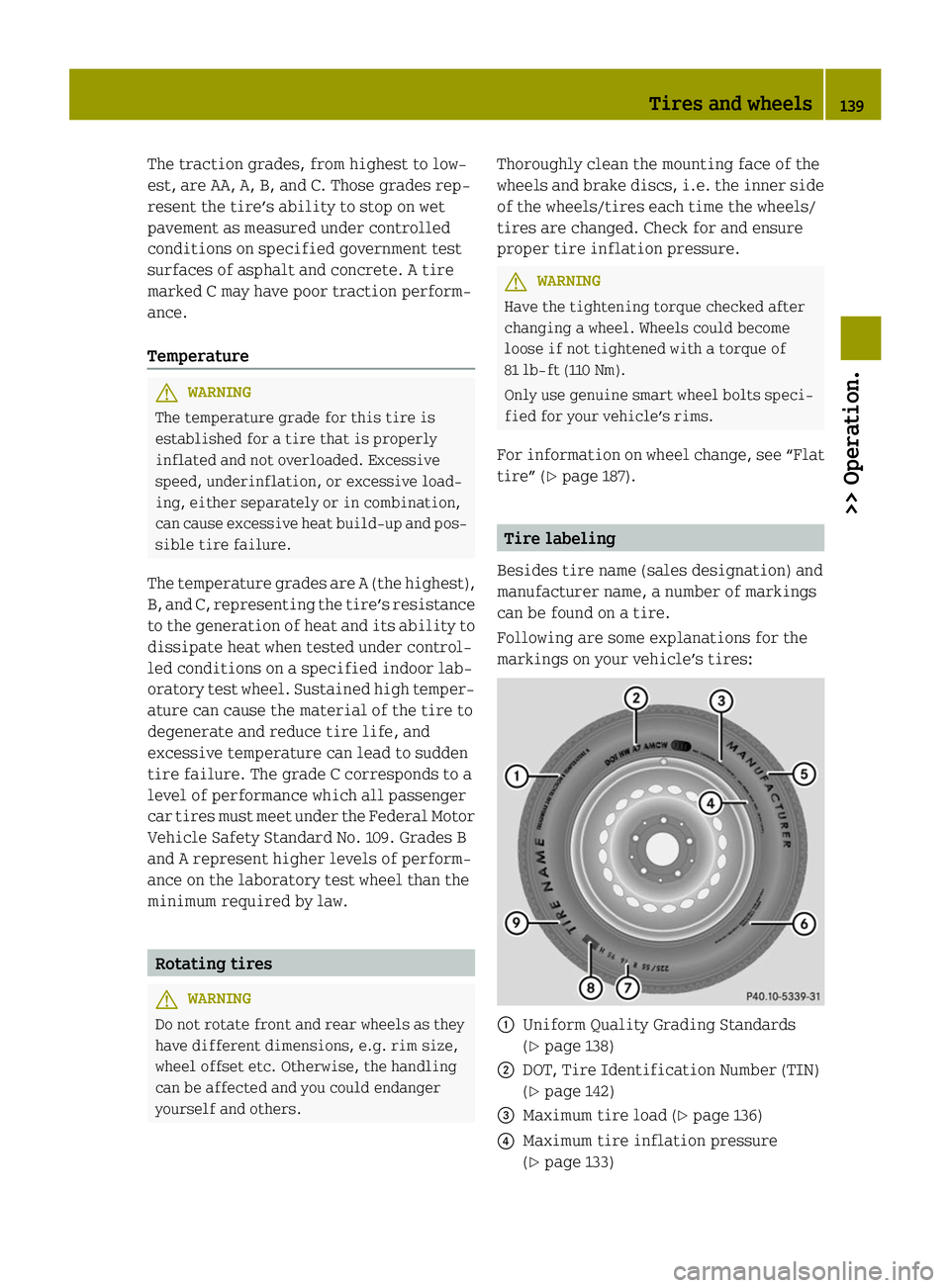
can be found on a tire.
Following are some explanations for the
markings on your vehicle’s tires: 0043
Uniform Quality Grading Standards
(Ypage 138)
0044 DOT, Tire Identification Number (TIN)
(Ypage 142)
0087 Maximum tire load (Y page 136)
0085 Maximum tire inflation pressure
(Ypage 133) Tires and wheels
139>> Operation. Z
Page 146 of 222
and heater, to the extent that these items
are available as factory-installed equip-
ment (whether installed or not).
Air pressure The amount of air inside the tire pressing
outward on each square inch of the tire. Air
pressure is expressed in pounds per square
inch (psi), or kilopascal (kPa) or bars.
Aspect ratio Dimensional relationship between tire
section height and section width expressed
in percentage.
Bar Another metric unit for air pressure. There
are 14.5038 pounds per square inch (psi) to
1 bar; there are 100 kilopascals (kPa) to
1 bar.
Bead The tire bead contains steel wires wrapped
by steel cords that hold the tire onto the
rim.
Cold tire inflation pressure Tire inflation pressure when your vehicle
has been sitting for at least 3 hours or
driven no more than 1 mile (1.6 km).
Curb weight The weight of a motor vehicle with standard
equipment including the maximum capa-
city of fuel, oil, and coolant, and, if so
equipped, air conditioning and additional
optional equipment, but without passen-
gers and cargo.
DOT (Department of Transportation) A tire branding symbol which denotes the
tire meets requirements of the U.S. Depart-
ment of Transportation. GAWR (Gross Axle Weight Rating) The GAWR is the maximum permissible axle
weight. The gross vehicle weight on each
axle must never exceed the GAWR for the
front and rear axle indicated on the cer-
tification label located on the driver’s
door B‑pillar.
GVW (Gross Vehicle Weight) The GVW comprises the weight of the vehi-
cle including fuel, tools, installed acces-
sories, passengers and cargo. The GVW must
never exceed the GVWR indicated on the
certification label located on the driver’s
door B‑pillar.
GVWR (Gross Vehicle Weight Rating)
This is the maximum permissible vehicle
weight of the fully loaded vehicle (weight
of the vehicle including all options, pas-
sengers, fuel, and cargo. It is indicated on
certification label located on the driver’s
door B‑pillar.
Kilopascal (kPa)
The metric unit for air pressure. There are
6.9 kPa to 1 psi; another metric unit for air
pressure is bars. There are 100 kilopas-
cals (kPa) to 1 bar.
Maximum load rating The maximum load in kilograms and pounds
that can be carried by the tire.
Maximum loaded vehicle weight
The sum of curb weight, accessory weight,
total load limit and production options
weight.
Maximum permissible tire inflation
pressure
This number is the greatest amount of air
pressure that should ever be put in the tire.144
Tires and wheels>> Operation.
Page 151 of 222
Wet road surface
G
WARNING
After driving in heavy rain for some time
without applying the brakes or through
water deep enough to wet brake components,
the first braking action may be somewhat
reduced and increased pedal pressure may
be necessary to obtain expected braking
effect. Maintain a safe distance from vehi-
cles in front.
To help prevent brake disc corrosion after
driving on wet road surfaces (particularly
salted roads), it is advisable to brake the
vehicle with considerable force prior to
parking. The heat generated serves to dry
the brakes. G
WARNING
Make sure not to endanger any other road
users when carrying out these braking
maneuvers.
Limited braking effect on salted roads Remember that the effect of the brakes can
be limited on salted road surfaces. A layer
of salt can form on brake discs and brake
pads, considerably reducing the friction
between the brake disc and the brake pad.
The effect is most noticeable after long
trips without braking, e.g. on the highway,
and after the vehicle has been parked for
several hours.
G
WARNING
The accumulation of salt on brake discs and
brake pads reduces braking effectiveness
and increases the distance necessary to
come to a complete standstill. This could
potentially cause an accident and/or per-
sonal injury.
To avoid this risk, you should
R brake carefully every now and then on
salted roads in order to remove any layer
of salt on the brake disc and brake pad, but do so without endangering any other
road users
R keep a good safe distance from the vehi-
cle in front and drive carefully
R press the brake carefully at the end of the
trip and again when beginning the next
trip in order to remove any salt residues
from the brake disc
New brake pads Only install brake pads recommended by
smart.
G
WARNING
If other than recommended brake pads are
installed, or other than recommended brake
fluid is used, the braking properties of the
vehicle can be degraded to an extent that
safe braking is substantially impaired.
This could result in an accident. G
WARNING
New brake pads will not achieve their opti-
mal braking effect until after several hun-
dred miles (kilometers). This means that
you must compensate for the reduced brak-
ing effect by pressing harder on the brake
pedal and adapt your driving style accord-
ingly. The same applies after brake pads or
brake discs have been changed. Drive sensibly - save energy
Energy consumption, to a great extent,
depends on driving habits and operating
conditions.
To save energy you should:
R Drive carefully and maintain a suitable
distance from the vehicle in front.
R Avoid frequent acceleration and decel-
eration.
R Keep tires at the recommended inflation
pressures.
R Remove carriers* when not in use. Driving instructions
149>> Operation.
* optional Z
Page 154 of 222
Standing water
Do not drive through flooded areas or water
of unknown depth. Before driving through
water, determine its depth. Never acceler-
ate before driving into water.
If you must drive through standing water,
drive slowly to prevent water from entering
R the front compartment
R the engine compartment
R the passenger compartment
! Water in these areas could cause dam-
age to
R electrical components
R electrical wiring
R the drive system
R the high-voltage battery
Any such damage is not covered by the
smart Limited Warranty. Passenger compartment
G
WARNING
Always fasten items being carried as
securely as possible.
In an accident, during hard braking or sud-
den maneuvers, loose items thrown around
inside the vehicle may injure vehicle
occupants.
The cargo compartment is the preferred
place to carry objects. Control and operation of radio trans-
mitters
Radio and telephone G
WARNING
Please do not forget that your primary
responsibility is to drive the vehicle
safely. Only operate the radio or tele- phone
8
if road, weather and traffic condi-
tions permit.
Bear in mind that at a speed of just 30 mph
(approximately 50 km/h), your vehicle is
covering a distance of 44 feet (approx-
imately 14 m) every second.
Telephones and two-way radios G
WARNING
Never operate radio transmitters equipped
with a built-in or attached antenna (i.e.
without being connected to an external
antenna) from inside the vehicle while the
drive system is switched on. Doing so could
lead to a malfunction of the vehicle’s elec-
tronic system, possibly resulting in an
accident and/or serious personal injury.
Radio transmitters, such as a mobile phone
or a citizens band unit should only be used
inside the vehicle if they are connected to
an antenna that is installed on the outside
of the vehicle.
Refer to the radio transmitter operation
instructions regarding use of an external
antenna. Coolant temperature
During severe operating conditions and
stop-and-go city traffic, the coolant tem-
perature may rise.
! Excessive coolant temperature causes
the red coolant temperature warning
lamp 00AC in the instrument cluster to
come on.
The drive system should not be operated
with the red coolant temperature warn-
ing lamp 00ACilluminated. Doing so may
cause serious damage to the drive system
and the high-voltage battery, which is
not covered by the smart Limited War-
ranty.
8 Observe all legal requirements. 152
Driving instructions>> Operation.
Page 159 of 222
!
Do not aim directly at
R electrical parts
R electrical connectors
R seals
R other rubber parts
The distance should be at least 3.9 in
(10 cm) and the water temperature must
not exceed 140¦ (60¥). Follow the
instructions provided by the power
washer manufacturer on maintaining a
distance between the vehicle and the
nozzle of the power washer.
Always keep the jet of water moving
across the surface.
! Powerwashing could damage
R the high-voltage battery
R the drive system
R the engine compartment
Do not powerwash these components.
Decorative foils !
Decorative foils are permanently
adhered to the painted parts of the vehi-
cle and cannot be removed.
! Do not expose the foils to solvents, gas-
oline or diesel.
i When cleaning with a power washer, note
the following guideline values:
R Water temperature max. 176 ¦(80¥)
R Minimum distance 11.8 in (30 cm)
R Jet of water strike at a right angle Paintwork care
The frequency with which you care for your
paintwork is dependent on
R how much the vehicle is used
R where you normally park the vehicle (e.g.
in a garage or under a tree)
R the season
R weather and environmental influences Rectifying paintwork damage You can use a touch-up paint pen to repair
minimal stone chip damage and scratches.
Recommended touch-up paint pens can be
obtained in a smart center.
i
For any major paintwork damage, please
contact a smart center. Exterior Repair options
Plastic parts (body
panels) with clear-
coat Clearcoat touch-up
paint pen
Body panels with
base coat and
clearcoat recommended
touch-up paint pen
set in the relevant
color
tridion safety cell recommended
touch-up paint pen
set in the relevant
color
Soft top system (cabriolet only)
Regular care will protect the retractable
soft top and the rear soft top against exter-
nal influences, helping to preserve its
value. Use only an approved soft top
cleaner when removing dirt from the soft
top.
! Never clean the soft top using a power
washer, as water could get into the inside
of the vehicle.
Cleaning the soft top fabric !
Only clean the retractable soft top and
the rear soft top when they are closed.
Dry cleaning
X Brush the soft top fabric with a soft
brush, always working in the same direc-
tion, i.e. from front to back. Vehicle care
157>> Operation. Z