front side SMART FORTWO COUPE ELECTRIC DRIVE 2014 Owner's Guide
[x] Cancel search | Manufacturer: SMART, Model Year: 2014, Model line: FORTWO COUPE ELECTRIC DRIVE, Model: SMART FORTWO COUPE ELECTRIC DRIVE 2014Pages: 222, PDF Size: 16.17 MB
Page 181 of 222
!
Check the polarity when inserting the
new transmitter battery. You could oth-
erwise damage parts of the electrical
system. When inserting the batteries,
make sure they are clean and free of lint.
X Insert the new transmitter battery.
X Press both halves of the key housing
together again.
X Check the operation of the remote
control. Replacing bulbs
About replacing bulbs
Safe vehicle operation depends on proper
exterior lighting and signaling. It is
therefore essential that all bulbs and lamp
assemblies are in good working order at all
times.
Correct headlamp adjustment is extremely
important. Have headlamps checked and
readjusted at regular intervals and when a
bulb has been replaced. Contact an author-
ized electric drive smart center for head-
lamp adjustment. G
WARNING
Bulbs and bulb sockets can be very hot.
Allow the lamp to cool down before changing
a bulb. Otherwise you could be burned if you
touch them.
Keep bulbs out of the reach of children.
Halogen lamps contain pressurized gas. A
bulb can explode if you:
R touch or move it when hot
R drop the bulb
R scratch the bulb
Wear eye and hand protection.
i If the headlamps or front fog lamps* are
fogged up on the inside as a result of
high humidity, driving the vehicle a
distance with the lights on should clear
up the fogging. Notes on bulb replacement:
R
Only use bulbs of the same type and with
the specified watt rating.
R Switch the lights off before replacing a
bulb to prevent short circuits.
R Always use a clean lint-free cloth when
handling bulbs.
R Your hands should be dry and free of oil
and grease.
R Avoid touching the glass of the bulb with
bare fingers.
R If the newly installed bulb does not come
on, contact an authorized electric drive
smart center.
R Have the bulbs for the front fog lamps*
and the LED daytime running lamps*
replaced at an authorized electric drive
smart center. Replacing bulbs
179>> Practical hints.
* optional Z
Page 182 of 222
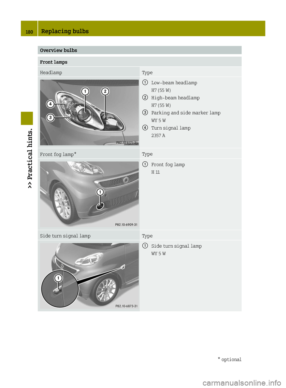
Overview bulbs
Front lamps
Headlamp Type
0043
Low‑beam headlamp
H7 (55 W)
0044 High‑beam headlamp
H7 (55 W)
0087 Parking and side marker lamp
WY 5 W
0085 Turn signal lamp
2357 A Front fog lamp* Type
0043
Front fog lamp
H 11 Side turn signal lamp Type
0043
Side turn signal lamp
WY 5 W 180
Replacing bulbs>> Practical hints.
* optional
Page 184 of 222
Replacing bulbs for front lamps
Before you start to replace a bulb for a
front lamp, do the following first:
X Turn the exterior lamp switch to position
003F (Ypage 64).
X Switch off the ignition.
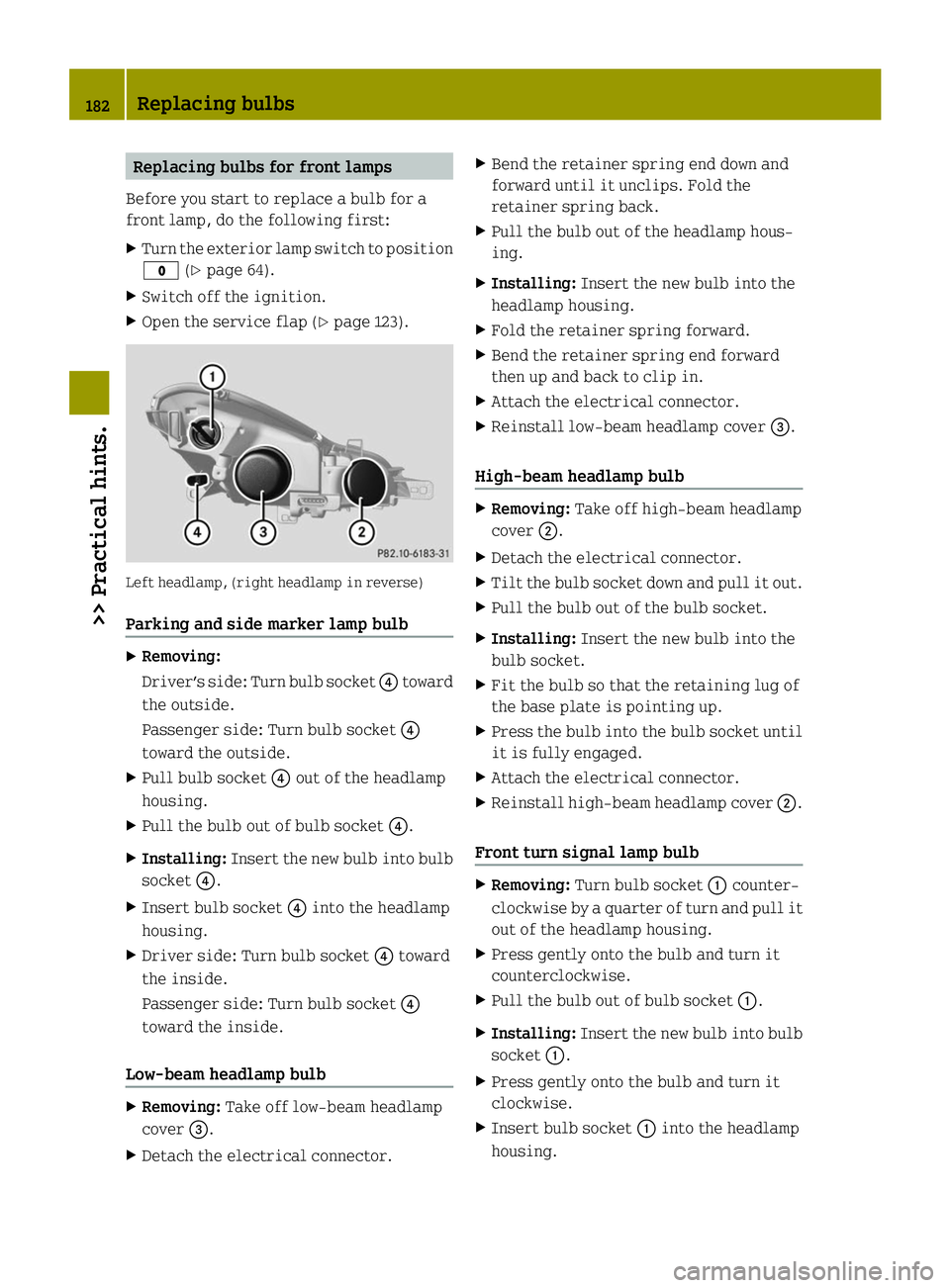
X Open the service flap (Y page 123).Left headlamp, (right headlamp in reverse)
Parking and side marker lamp bulb X
Removing:
Driver’s side: Turn bulb socket 0085toward
the outside.
Passenger side: Turn bulb socket 0085
toward the outside.
X Pull bulb socket 0085out of the headlamp
housing.
X Pull the bulb out of bulb socket 0085.
X Installing: Insert the new bulb into bulb
socket 0085.
X Insert bulb socket 0085into the headlamp
housing.
X Driver side: Turn bulb socket 0085toward
the inside.
Passenger side: Turn bulb socket 0085
toward the inside.
Low‑beam headlamp bulb X
Removing: Take off low‑beam headlamp
cover 0087.
X Detach the electrical connector. X
Bend the retainer spring end down and
forward until it unclips. Fold the
retainer spring back.
X Pull the bulb out of the headlamp hous-
ing.
X Installing: Insert the new bulb into the
headlamp housing.
X Fold the retainer spring forward.
X Bend the retainer spring end forward
then up and back to clip in.
X Attach the electrical connector.
X Reinstall low‑beam headlamp cover 0087.
High‑beam headlamp bulb X
Removing: Take off high‑beam headlamp
cover 0044.
X Detach the electrical connector.
X Tilt the bulb socket down and pull it out.
X Pull the bulb out of the bulb socket.
X Installing: Insert the new bulb into the
bulb socket.
X Fit the bulb so that the retaining lug of
the base plate is pointing up.
X Press the bulb into the bulb socket until
it is fully engaged.
X Attach the electrical connector.
X Reinstall high‑beam headlamp cover 0044.
Front turn signal lamp bulb X
Removing: Turn bulb socket 0043counter-
clockwise by a quarter of turn and pull it
out of the headlamp housing.
X Press gently onto the bulb and turn it
counterclockwise.
X Pull the bulb out of bulb socket 0043.
X Installing: Insert the new bulb into bulb
socket 0043.
X Press gently onto the bulb and turn it
clockwise.
X Insert bulb socket 0043into the headlamp
housing. 182
Replacing bulbs>> Practical hints.
Page 197 of 222
Wheel change
Preparing the vehicle
X Park the vehicle on a hard, flat surface
when possible.
X Turn on the hazard warning flasher.
X Turn the steering wheel so that the front
wheels are in a straight-ahead position.
X Engage the parking brake.
X Move the gear selector lever to park
position P.
X Switch off the drive system.
X Have any passenger exit the vehicle at a
safe distance from the roadway. Removing the wheel
G
WARNING
When jacking up the vehicle, only use a
suitable jack. Observe the manufacturer’s
safety instructions.
The jack must be designed for jacking up
this vehicle at the jack take-up brackets
built into both sides of the vehicle.
The jack is intended only for lifting the
vehicle briefly for wheel changes. It is not
suited for performing maintenance work
under the vehicle. To help avoid personal
injury, use the jack only to lift the vehicle
during a wheel change.
Never get beneath the vehicle while it is
supported by the jack. Keep hands and feet
away from the area under the lifted vehicle.
Always lower the vehicle onto sufficient
capacity jackstands before working under
the vehicle.
Always firmly engage the parking brake and
block the wheels with wheel chocks or other
sizeable objects before raising the vehi-
cle with the jack. Do not release the parking
brake while the vehicle is raised.
Make sure the ground on which the vehicle
is standing and where you place the jack is solid, level and not slippery. If necessary,
use a large underlay. On slippery surfaces,
such as tiled floors, you should use a non-
slip underlay, for example a rubber mat.
Do not use wooden blocks or similar objects
to support the jack. Otherwise the jack may
not be able to achieve its load-bearing
capacity if it is not at its full height.
The jack must always be vertical when in
use. Always try to use the jack on level sur-
face. If you do not position the jack cor-
rectly, the vehicle can fall off the jack and
seriously or fatally injure you or others.
Never switch on the drive system when the
vehicle is raised.
Also observe the notes on the jack.
X Make sure to have a suitable jack 10
, wheel
wrench 10
and wheel chock 10
.
Contact an authorized electric drive
smart center for information on which
jack and wheel wrench are required.
X Prepare the vehicle as described
(Y page 195).
X Make sure the surface is level.
Prevent the vehicle from rolling away by
blocking wheels with wheel chocks or other
sizeable objects:
X Place one wheel chock or other sizeable
object in front of and another wheel
chock or other sizeable object behind
the wheel that is diagonally opposite to
the wheel being changed.
X On wheel to be changed, loosen but do not
yet remove the wheel bolts (approx-
imately one full turn with wheel wrench).
! Only position the jack on the desig-
nated take-up brackets.
You must not position the jack under the
high-voltage battery. Otherwise, the
high-voltage battery could be damaged.
10 Not included and not available as factory equipment. Wheel change
195>> Practical hints. Z
Page 206 of 222
A tow bar is necessary to adequately control
the towed vehicle.
Prior to towing the vehicle with all wheels
on the ground, make sure the gear selector
lever is in neutral position Nand the igni-
tion is switched on. G
WARNING
With the drive system inactive, there is no
power assistance for the brake and steering
systems. In this case, it is important to
keep in mind that a considerably higher
degree of effort is necessary to brake and
steer the vehicle. Adapt your driving
accordingly.
! The vehicle may be towed only for dis-
tances up to 30 miles (50 km) and at a
speed not to exceed 30 mph (50 km/h).
Otherwise, the electric drive or the
high-voltage system could be damaged.
! Do not tow other vehicles.
Otherwise, the drive system or compo-
nents of the high-voltage system could be
damaged.
! Do not tow the vehicle with the front
axle raised. Doing so may cause serious
damage to the brake system which is not
covered by the smart Limited Warranty.
! Before towing the vehicle observe the
following instructions:
R Do not tow with sling-type equipment
attached to suspension parts. This may
cause damage to the supports if towing
on a bumpy road.
R Towing the vehicle should only be done
using the properly installed towing
eye bolt. Never attach a tow cable, tow
rope, or tow rod to the vehicle chassis,
frame, or suspension parts.
! Make sure the gear selector lever is in
neutral position Nwhile towing the
vehicle. Doing otherwise may result in
significant drive train damage. !
Towing the vehicle with a luggage
rack* mounted is not permissible. The
vehicle must not be towed by the luggage
rack*.
i If the 12-volt battery is disconnected
or discharged, the gear selector lever
will remain locked in park position P.
Contact an authorized electric drive
smart center for assistance or call Road-
side Assistance.
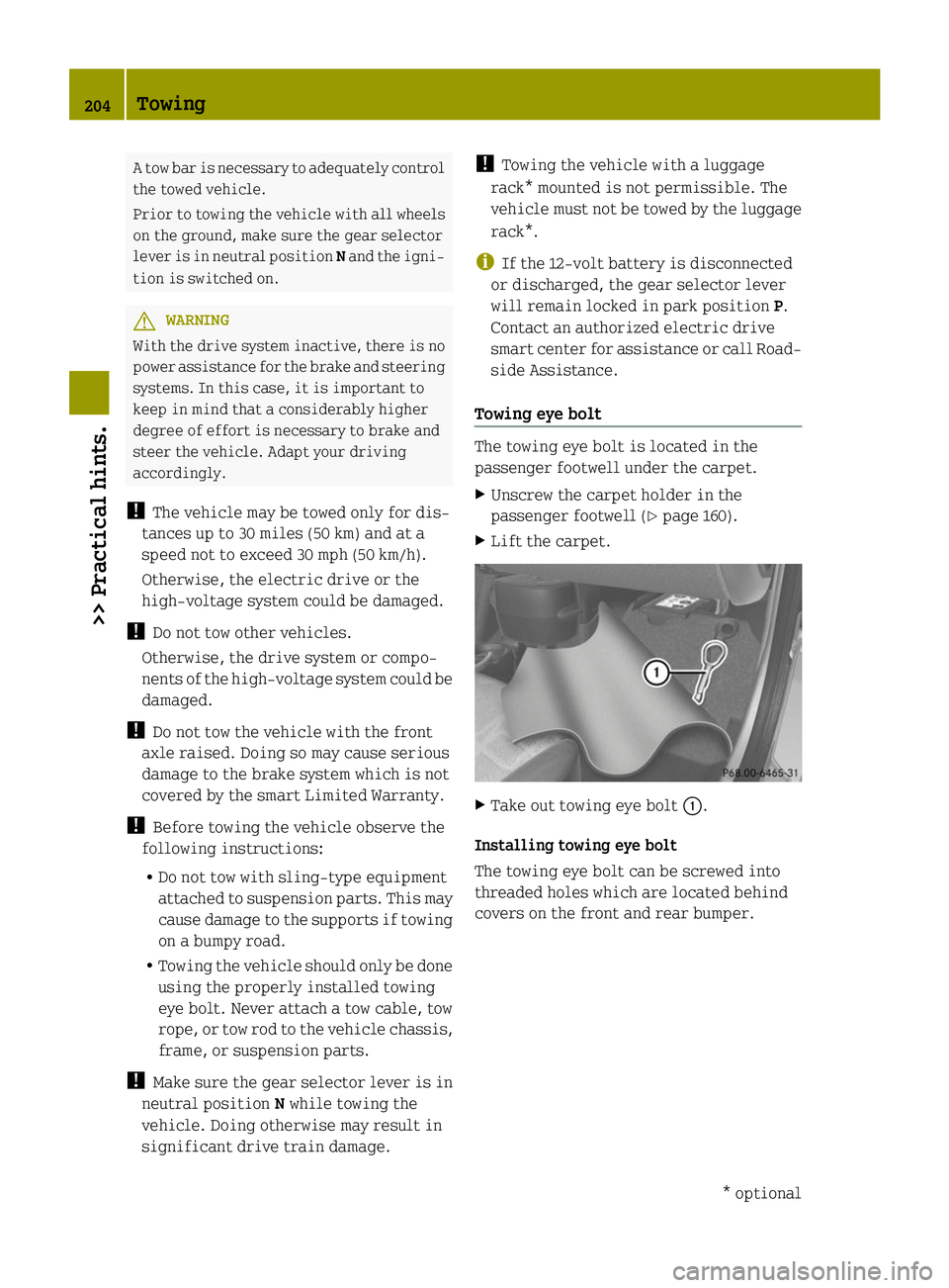
Towing eye bolt The towing eye bolt is located in the
passenger footwell under the carpet.
X
Unscrew the carpet holder in the
passenger footwell (Y page 160).
X Lift the carpet. X
Take out towing eye bolt 0043.
Installing towing eye bolt
The towing eye bolt can be screwed into
threaded holes which are located behind
covers on the front and rear bumper. 204
Towing>> Practical hints.
* optional
Page 209 of 222
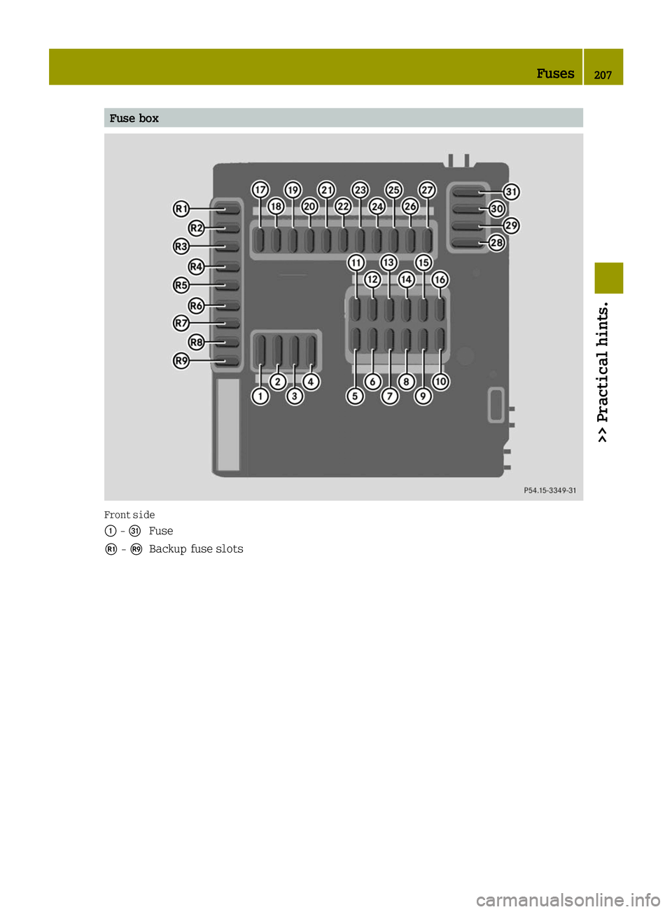
Fuse box
Front side
0043
-006A
Fuse
009A -00A2
Backup fuse slots Fuses
207>> Practical hints. Z
Page 210 of 222
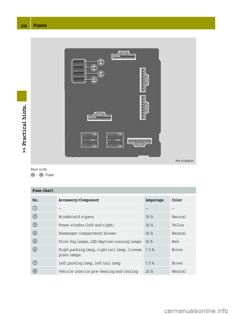
Rear side
0069
-00B7
Fuse Fuse chart
No. Accessory/Component Amperage Color
0043
— — —
0044
Windshield wipers 25 A Neutral
0087
Power window (left and right) 20 A Yellow
0085
Passenger compartment blower 25 A Neutral
0083
Front fog lamps, LED daytime running lamps 10 A Red
0084
Right parking lamp, right tail lamp, license
plate lamps 7.5 A Brown
006B
Left parking lamp, left tail lamp 7.5 A Brown
006C
Vehicle interior pre-heating and cooling 25 A Neutral208
Fuses>> Practical hints.