ecm SSANGYONG KORANDO 1997 Service Repair Manual
[x] Cancel search | Manufacturer: SSANGYONG, Model Year: 1997, Model line: KORANDO, Model: SSANGYONG KORANDO 1997Pages: 2053, PDF Size: 88.33 MB
Page 1181 of 2053

5A-86 AUTOMATIC TRANSMISSION
SSANGYONG MY2002
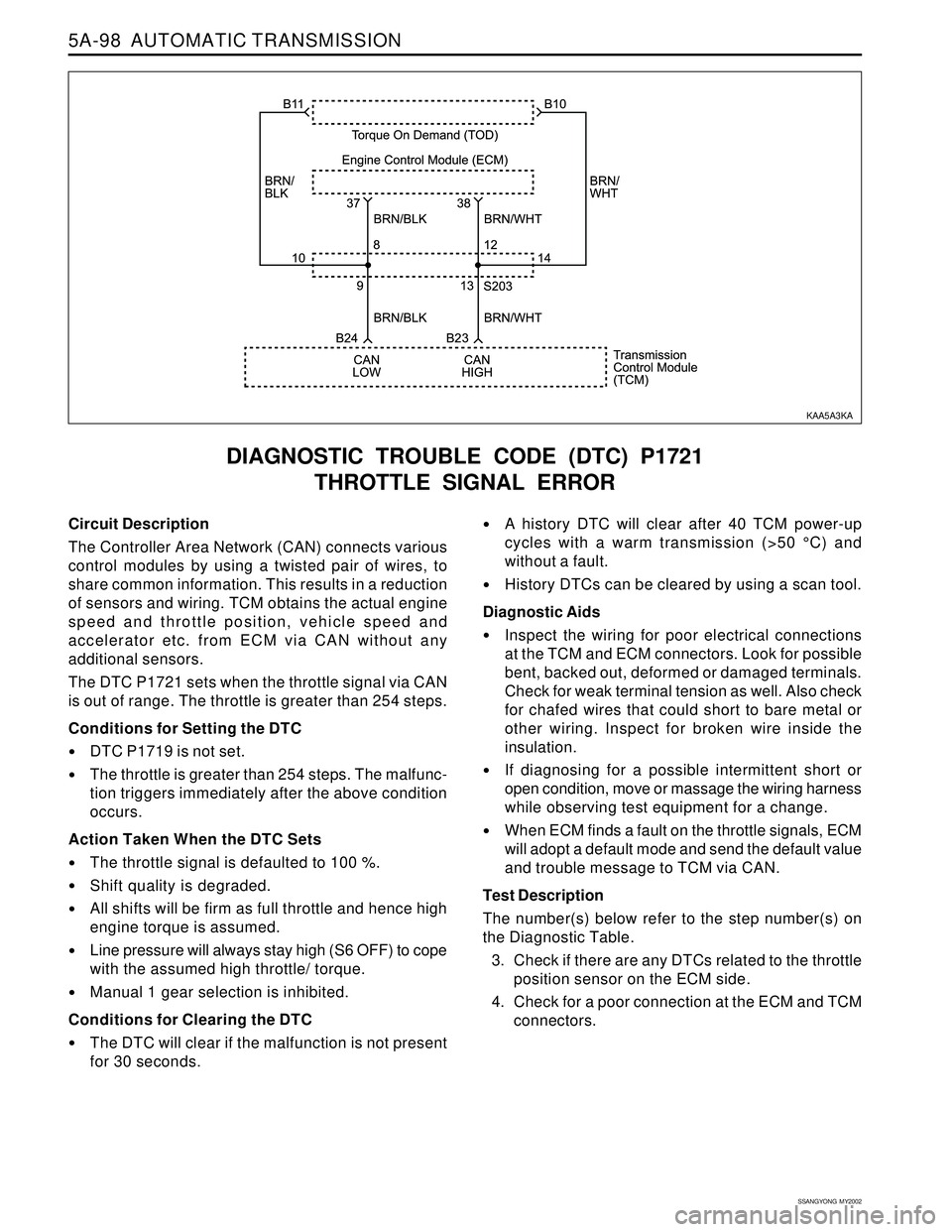
Circuit Description
The Controller Area Network (CAN) connects various
control modules by using a twisted pair of wires, to
share common information. This results in a reduction
of sensors and wiring. TCM obtains the actual engine
speed and throttle position, vehicle speed and
accelerator pedal position etc. from ECM via CAN
without any additional sensors.
The DTC P1713 sets when the accelerator pedal signal
via CAN is out of range. The accelerator pedal signal
is greater than 254 steps.
Conditions for Setting the DTC
DTCs P1719 is not set.
The accelerator pedal signal is greater than 254
steps. The malfunction is triggered immediately
after this condition exists.
Action Taken When the DTC Sets
4th gear is inhibited.
Torque Converter Clutch (TCC) is inhibited.
Default value is adopted for shift point decisions.
Accelerator pedal is not used for P, R, or N B2
activation decisions.
Conditions for Clearing the DTC
The DTC will clear when the malfunction has not
occurred for 30 seconds.
DIAGNOSTIC TROUBLE CODE (DTC) P1713
PEDAL SIGNAL ERROR
A history DTC will clear after 40 TCM power-up
cycles with a warm transmission (>50 °C) and
without a fault.
History DTCs can be cleared by using a scan tool.
Diagnostic Aids
Inspect the wiring for poor electrical connections
at the TCM and ECM connectors. Look for possible
bent, backed out, deformed or damaged terminals.
Check for weak terminal tension as well. Also check
for chafed wires that could short to bare metal or
other wiring. Inspect for broken wire inside the
insulation.
If diagnosing for a possible intermittent short or
open condition, move or massage the wiring harness
while observing test equipment for a change.
When ECM finds a fault on the accelerator pedal
signals, ECM will adopt a default mode and send
the default value and trouble message to TCM via
CAN.
Test Description
The number(s) below refer to the step number(s) on
the Diagnostic Table.
3. Check if there are any DTCs related to the accelera-
tor pedal sensor on the ECM side.
4. Check for a poor connection at the ECM and TCM
connectors.
KAA5A5KA
Page 1182 of 2053

AUTOMATIC TRANSMISSION 5A-87
SSANGYONG MY2002
DTC P1713 Pedal Signal Error
1Perform a Transmission Control Module (TCM) Diag-
nostic System Check.
Is the check performed?
1. Install the scan tool.
2. Turn the ignition ON, with the engine OFF.
3. Record and then clear DTCs.
4. Operate the vehicle within the conditions for
setting this DTC as specified in the text.
Does the scan tool display P1713?
Check if there are any DTCs related to the accelerator
pedal sensor on the ECM side.
Are any DTCs related to accelerator pedal sensor
found?
1. Turn the ignition OFF.
2. Replace the TCM.
Is the action complete?
1. Using the scan tool, clear the DTCs.
2. Road test the vehicle within the conditions for
setting this DTC as specified in the text.
Does the scan tool indicate that this diagnostic has
run and passed?
Check if any DTCs are set.
Are there any DTCs displayed or previously recorded
at Step 2 that have not been diagnosed?
StepAction Value(s) Yes No
2
3
- Go to Step 5 - 4
- Go to Step 6 Go to Step 2 5
6
- Go to Step 2Go to “TCM
Diagnostic
System Check”
- Go to Step 3 Go to
“Diagnostic
Aids”
- Go to Section
1F, Engine
Controls Go to Step 4
-Go to
applicable
DTC tableSystem OK,
Check
Complete
Page 1185 of 2053

5A-90 AUTOMATIC TRANSMISSION
SSANGYONG MY2002
Circuit Description
The Controller Area Network (CAN) connects various
control modules by using a twisted pair of wires, to
share common information. This results in a reduction
of sensors and wiring. TCM obtains the actual engine
speed and throttle position, vehicle speed and
accelerator etc. from ECM via CAN without any
additional sensors.
The DTC P1716 sets when the throttle signal via CAN
is out of range. The throttle is greater than 254 steps.
Conditions for Setting the DTC
The minimum & maximum throttle positions have
not been learnt by the TCU.
Action Taken When the DTC Sets
The minimum & maximum throttle positions are set
to their factory default values.
Incorrect sensitivity to driver demand.
Incorrect gear shift points.
DIAGNOSTIC TABLE CODE (DTC) 1716
THROTTLE NOT LEARNT ERROR
Conditions for Clearing the DTC
Throttle learns 0 % position. This value must be
greater than 0.2 V.
Diagnostic Aids
This fault indicates that the TCU has not learnt the
throttle position correctly since installation in the
vehicle or that the throttle setting have been cleared
by a diagnostic tool.
Test Description
The number(s) below refer to the step number(s) on
the Diagnostic Table.
4. The “Throttle Position Calibration Procedure” needs
to be carried out. This is given in this section.
KAA5A5U0
Page 1189 of 2053

5A-94 AUTOMATIC TRANSMISSION
SSANGYONG MY2002
Circuit Description
The Controller Area Network (CAN) connects various
control modules by using a twisted pair of wires, to
share common information. This results in a reduction
of sensors and wiring. TCM obtains the actual engine
speed and throttle position, vehicle speed and
accelerator position etc. from ECM via CAN without
any additional sensors.
The DTC P1719 sets when the information required by
TCM is not available on the CAN. One or more CAN
messages used by the TCM is timed out, i.e. not re-
freshed for 1 second.
Conditions for Setting the DTC
One or more CAN messages used by the TCM are
timed out, i.e. not refreshed for 1 second.
Action Taken When the DTC Sets
TCM uses default values for all CAN dependent sig-
nals.
Conditions for Clearing the DTC
The DTC will clear when the malfunction has not
occurred for 30 seconds.
DIAGNOSTIC TROUBLE CODE (DTC) P1719
CAN BUS ERROR
A history DTC will clear after 40 TCM power-up
cycles with a warm transmission (>50 °C) and
without a fault.
History DTCs can be cleared by using a scan tool.
Diagnostic Aids
Inspect the wiring for poor electrical connections
at the TCM and ECM connectors. Look for possible
bent, backed out, deformed or damaged terminals.
Check for weak terminal tension as well. Also check
for chafed wires that could short to bare metal or
other wiring. Inspect for broken wire inside the
insulation.
If diagnosing for a possible intermittent short or
open condition, move or massage the wiring harness
while observing test equipment for a change.
Test Description
The number(s) below refer to the step number(s) on
the Diagnostic Table.
6. Check for a poor connection at the ECM and TCM
connectors.
KAA5A3KA
Page 1190 of 2053

AUTOMATIC TRANSMISSION 5A-95
SSANGYONG MY2002
DTC P1719 CAN Bus Error
1Perform a Transmission Control Module (TCM) Diag-
nostic System Check.
Is the check performed?
1. Install the scan tool.
2. Turn the ignition ON, with the engine OFF.
3. Record and then clear DTCs.
4. Operate the vehicle within the conditions for
setting this DTC as specified in the text.
Does the scan tool display P1719?
1. Turn the ignition OFF.
2. Disconnect the TCM connector B.
3. Disconnect the Engine Control Module (ECM)
connector.
4. Check the wiring harness from ECM connector
terminal 38 to TCM connector terminal B23 for an
open or a short.
Is a problem found?
Repair the malfunctioning wiring harness.
Is a repair complete?
Check the wiring harness from ECM connector termi-
nal 37 to TCM connector terminal B24 for an open or a
short.
Is a problem found?
Check for a poor connection at the ECM connector or
TCM connector and repair the malfunctioning terminals
as necessary.
Is a repair necessary?
1. Turn the ignition OFF.
2. Replace the TCM.
Is the action complete?
1. Using the scan tool, clear the DTCs.
2. Road test the vehicle within the conditions for
setting this DTC as specified in the text.
Does the scan tool indicate that this diagnostic has
run and passed?
1. Turn the ignition OFF.
2. Replace the TCM with the original.
1. Using the scan tool, clear the DTCs.
2. Road test the vehicle within the conditions for
setting this DTC as specified in the text.
Does the scan tool indicate that this diagnostic has
run and passed?
Check if any DTCs are set.
Are there any DTCs displayed or previously recorded
at Step 2 that have not been diagnosed?
StepAction Value(s) Yes No
2
3
5
- Go to Step 8 - 6 4
- Go to Step 10 Go to Step 9 7
8
- Go to Step 11 Go to Step 2 9
10
- Go to Step 2Go to “TCM
Diagnostic
System Check”
-
Go to Step 4 Go to Step 5
- Go to Step 3 Go to
“Diagnostic
Aids”
11
-Go to
applicable
DTC tableSystem OK,
Check
Complete
- Go to Step 4 Go to Step 6
-Go to
Section 1F,
Engine Control-
- Go to Step 10 Go to Step 7
-
Go to Step 10-
Page 1193 of 2053
5A-98 AUTOMATIC TRANSMISSION
SSANGYONG MY2002
Circuit Description
The Controller Area Network (CAN) connects various
control modules by using a twisted pair of wires, to
share common information. This results in a reduction
of sensors and wiring. TCM obtains the actual engine
speed and throttle position, vehicle speed and
accelerator etc. from ECM via CAN without any
additional sensors.
The DTC P1721 sets when the throttle signal via CAN
is out of range. The throttle is greater than 254 steps.
Conditions for Setting the DTC
DTC P1719 is not set.
The throttle is greater than 254 steps. The malfunc-
tion triggers immediately after the above condition
occurs.
Action Taken When the DTC Sets
The throttle signal is defaulted to 100 %.
Shift quality is degraded.
All shifts will be firm as full throttle and hence high
engine torque is assumed.
Line pressure will always stay high (S6 OFF) to cope
with the assumed high throttle/ torque.
Manual 1 gear selection is inhibited.
Conditions for Clearing the DTC
The DTC will clear if the malfunction is not present
for 30 seconds.
DIAGNOSTIC TROUBLE CODE (DTC) P1721
THROTTLE SIGNAL ERROR
A history DTC will clear after 40 TCM power-up
cycles with a warm transmission (>50 °C) and
without a fault.
History DTCs can be cleared by using a scan tool.
Diagnostic Aids
Inspect the wiring for poor electrical connections
at the TCM and ECM connectors. Look for possible
bent, backed out, deformed or damaged terminals.
Check for weak terminal tension as well. Also check
for chafed wires that could short to bare metal or
other wiring. Inspect for broken wire inside the
insulation.
If diagnosing for a possible intermittent short or
open condition, move or massage the wiring harness
while observing test equipment for a change.
When ECM finds a fault on the throttle signals, ECM
will adopt a default mode and send the default value
and trouble message to TCM via CAN.
Test Description
The number(s) below refer to the step number(s) on
the Diagnostic Table.
3. Check if there are any DTCs related to the throttle
position sensor on the ECM side.
4. Check for a poor connection at the ECM and TCM
connectors.
KAA5A3KA
Page 1194 of 2053
AUTOMATIC TRANSMISSION 5A-99
SSANGYONG MY2002
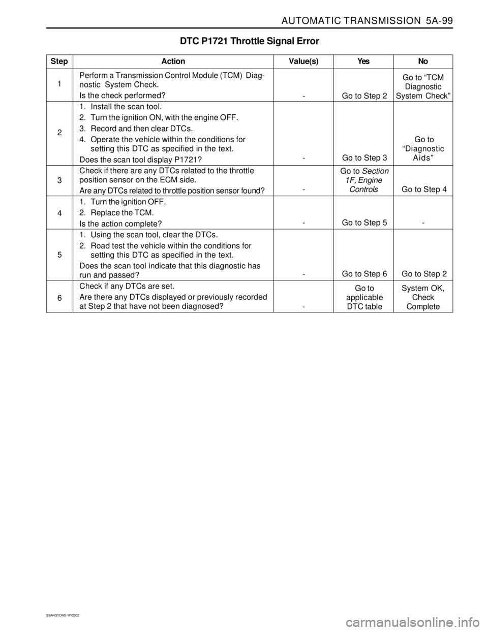
DTC P1721 Throttle Signal Error
1Perform a Transmission Control Module (TCM) Diag-
nostic System Check.
Is the check performed?
1. Install the scan tool.
2. Turn the ignition ON, with the engine OFF.
3. Record and then clear DTCs.
4. Operate the vehicle within the conditions for
setting this DTC as specified in the text.
Does the scan tool display P1721?
Check if there are any DTCs related to the throttle
position sensor on the ECM side.
Are any DTCs related to throttle position sensor found?
1. Turn the ignition OFF.
2. Replace the TCM.
Is the action complete?
1. Using the scan tool, clear the DTCs.
2. Road test the vehicle within the conditions for
setting this DTC as specified in the text.
Does the scan tool indicate that this diagnostic has
run and passed?
Check if any DTCs are set.
Are there any DTCs displayed or previously recorded
at Step 2 that have not been diagnosed?
StepAction Value(s) Yes No
2
3
- Go to Step 5 - 4
- Go to Step 6 Go to Step 2 5
6
- Go to Step 2Go to “TCM
Diagnostic
System Check”
- Go to Step 3 Go to
“Diagnostic
Aids”
- Go to Section
1F, Engine
Controls Go to Step 4
-Go to
applicable
DTC tableSystem OK,
Check
Complete
Page 1255 of 2053
5A-160 AUTOMATIC TRANSMISSION
SSANGYONG MY2002
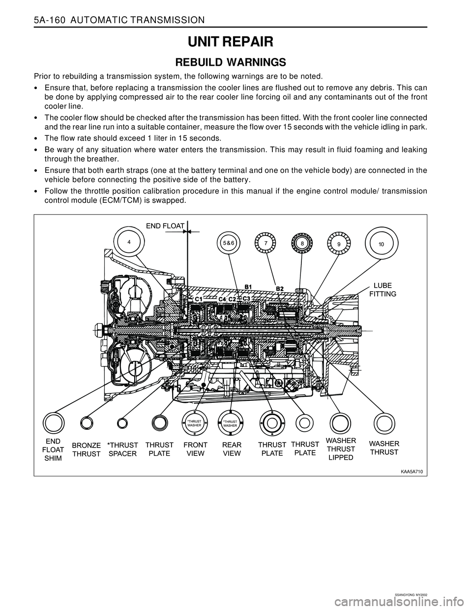
UNIT REPAIR
REBUILD WARNINGS
Prior to rebuilding a transmission system, the following warnings are to be noted.
Ensure that, before replacing a transmission the cooler lines are flushed out to remove any debris. This can
be done by applying compressed air to the rear cooler line forcing oil and any contaminants out of the front
cooler line.
The cooler flow should be checked after the transmission has been fitted. With the front cooler line connected
and the rear line run into a suitable container, measure the flow over 15 seconds with the vehicle idling in park.
The flow rate should exceed 1 liter in 15 seconds.
Be wary of any situation where water enters the transmission. This may result in fluid foaming and leaking
through the breather.
Ensure that both earth straps (one at the battery terminal and one on the vehicle body) are connected in the
vehicle before connecting the positive side of the battery.
Follow the throttle position calibration procedure in this manual if the engine control module/ transmission
control module (ECM/TCM) is swapped.
KAA5A710
Page 1375 of 2053
TRANSFER CASE 5D1-5
SSANGYONG MY2002
The motor reaches its destination.
The motor is on for 5 seconds without reaching its
destination. The shift has failed and the TCCU will
respond as default mode.
A fault occurs with either the motor or position
encoder. Refer to the diagnosis requirement.
When the motor is energized, the Ignition, 4H/4L
switch, propeller shaft speeds, and transmission
neutral inputs are ignored.
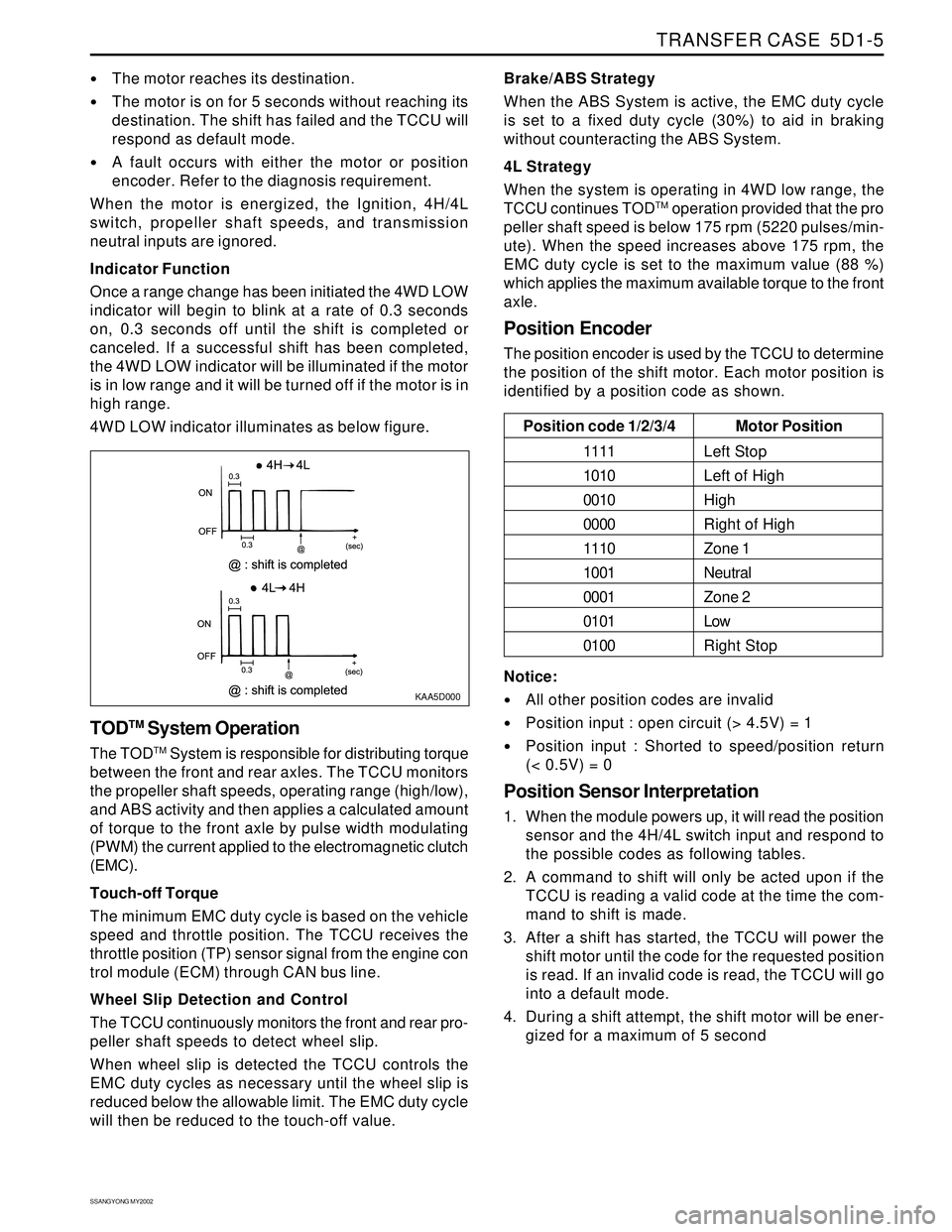
Indicator Function
Once a range change has been initiated the 4WD LOW
indicator will begin to blink at a rate of 0.3 seconds
on, 0.3 seconds off until the shift is completed or
canceled. If a successful shift has been completed,
the 4WD LOW indicator will be illuminated if the motor
is in low range and it will be turned off if the motor is in
high range.
4WD LOW indicator illuminates as below figure.
KAA5D000
TODTM System Operation
The TODTM System is responsible for distributing torque
between the front and rear axles. The TCCU monitors
the propeller shaft speeds, operating range (high/low),
and ABS activity and then applies a calculated amount
of torque to the front axle by pulse width modulating
(PWM) the current applied to the electromagnetic clutch
(EMC).
Touch-off Torque
The minimum EMC duty cycle is based on the vehicle
speed and throttle position. The TCCU receives the
throttle position (TP) sensor signal from the engine con
trol module (ECM) through CAN bus line.
Wheel Slip Detection and Control
The TCCU continuously monitors the front and rear pro-
peller shaft speeds to detect wheel slip.
When wheel slip is detected the TCCU controls the
EMC duty cycles as necessary until the wheel slip is
reduced below the allowable limit. The EMC duty cycle
will then be reduced to the touch-off value.Brake/ABS Strategy
When the ABS System is active, the EMC duty cycle
is set to a fixed duty cycle (30%) to aid in braking
without counteracting the ABS System.
4L Strategy
When the system is operating in 4WD low range, the
TCCU continues TOD
TM operation provided that the pro
peller shaft speed is below 175 rpm (5220 pulses/min-
ute). When the speed increases above 175 rpm, the
EMC duty cycle is set to the maximum value (88 %)
which applies the maximum available torque to the front
axle.
Position Encoder
The position encoder is used by the TCCU to determine
the position of the shift motor. Each motor position is
identified by a position code as shown.
Motor Position
Left Stop
Left of High
High
Right of High
Zone 1
Neutral
Zone 2
Low
Right Stop Position code 1/2/3/4
1111
1010
0010
0000
1110
1001
0001
0101
0100
Notice:
All other position codes are invalid
Position input : open circuit (> 4.5V) = 1
Position input : Shorted to speed/position return
(< 0.5V) = 0
Position Sensor Interpretation
1. When the module powers up, it will read the position
sensor and the 4H/4L switch input and respond to
the possible codes as following tables.
2. A command to shift will only be acted upon if the
TCCU is reading a valid code at the time the com-
mand to shift is made.
3. After a shift has started, the TCCU will power the
shift motor until the code for the requested position
is read. If an invalid code is read, the TCCU will go
into a default mode.
4. During a shift attempt, the shift motor will be ener-
gized for a maximum of 5 second
Page 1664 of 2053
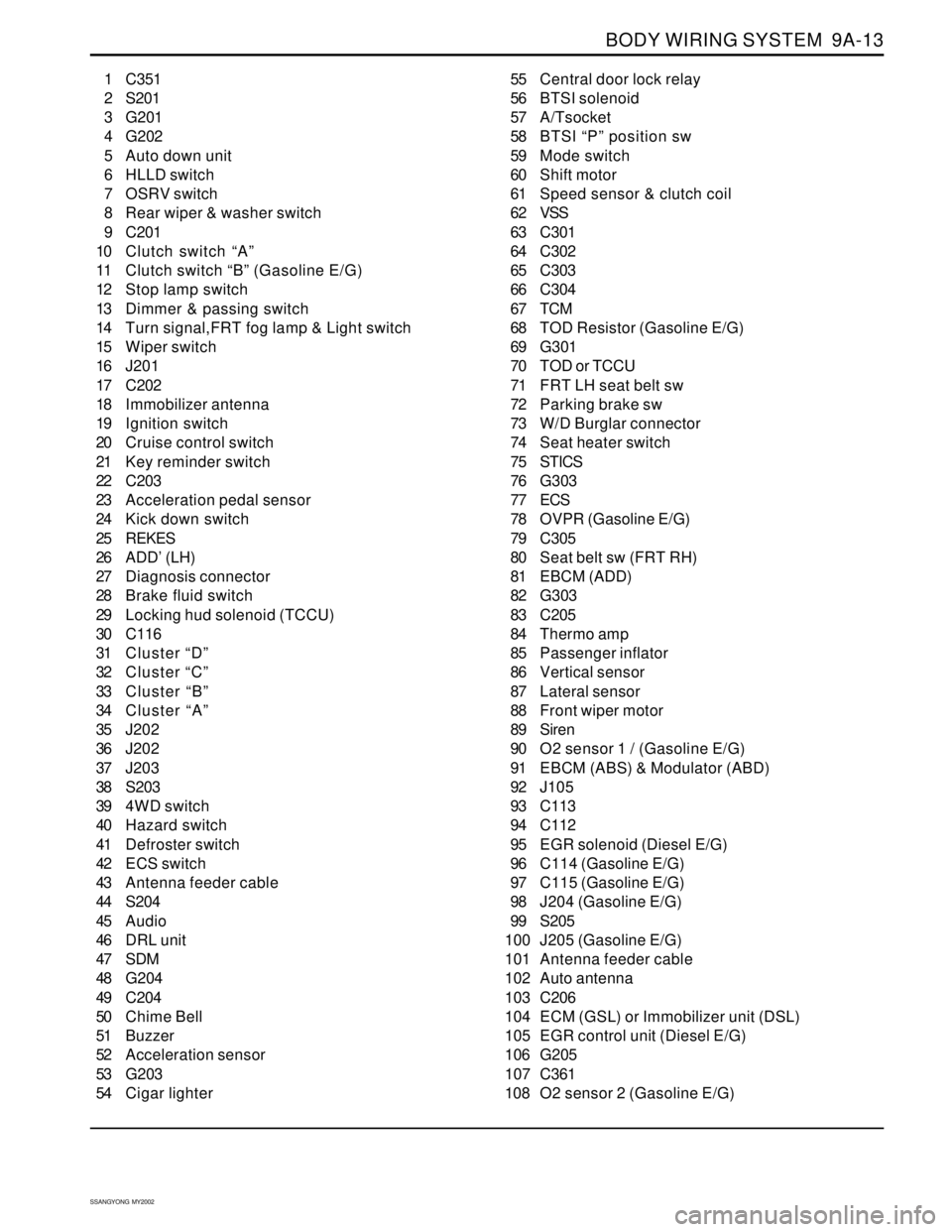
BODY WIRING SYSTEM 9A-13
SSANGYONG MY2002
1 C351
2 S201
3 G201
4 G202
5 Auto down unit
6 HLLD switch
7 OSRV switch
8 Rear wiper & washer switch
9 C201
10 Clutch switch “A”
11 Clutch switch “B” (Gasoline E/G)
12 Stop lamp switch
13 Dimmer & passing switch
14 Turn signal,FRT fog lamp & Light switch
15 Wiper switch
16 J201
17 C202
18 Immobilizer antenna
19 Ignition switch
20 Cruise control switch
21 Key reminder switch
22 C203
23 Acceleration pedal sensor
24 Kick down switch
25 REKES
26 ADD’ (LH)
27 Diagnosis connector
28 Brake fluid switch
29 Locking hud solenoid (TCCU)
30 C116
31 Cluster “D”
32 Cluster “C”
33 Cluster “B”
34 Cluster “A”
35 J202
36 J202
37 J203
38 S203
39 4WD switch
40 Hazard switch
41 Defroster switch
42 ECS switch
43 Antenna feeder cable
44 S204
45 Audio
46 DRL unit
47 SDM
48 G204
49 C204
50 Chime Bell
51 Buzzer
52 Acceleration sensor
53 G203
54 Cigar lighter55 Central door lock relay
56 BTSI solenoid
57 A/Tsocket
58 BTSI “P” position sw
59 Mode switch
60 Shift motor
61 Speed sensor & clutch coil
62 VSS
63 C301
64 C302
65 C303
66 C304
67 TCM
68 TOD Resistor (Gasoline E/G)
69 G301
70 TOD or TCCU
71 FRT LH seat belt sw
72 Parking brake sw
73 W/D Burglar connector
74 Seat heater switch
75 STICS
76 G303
77 ECS
78 OVPR (Gasoline E/G)
79 C305
80 Seat belt sw (FRT RH)
81 EBCM (ADD)
82 G303
83 C205
84 Thermo amp
85 Passenger inflator
86 Vertical sensor
87 Lateral sensor
88 Front wiper motor
89 Siren
90 O2 sensor 1 / (Gasoline E/G)
91 EBCM (ABS) & Modulator (ABD)
92 J105
93 C113
94 C112
95 EGR solenoid (Diesel E/G)
96 C114 (Gasoline E/G)
97 C115 (Gasoline E/G)
98 J204 (Gasoline E/G)
99 S205
100 J205 (Gasoline E/G)
101 Antenna feeder cable
102 Auto antenna
103 C206
104 ECM (GSL) or Immobilizer unit (DSL)
105 EGR control unit (Diesel E/G)
106 G205
107 C361
108 O2 sensor 2 (Gasoline E/G)