battery SSANGYONG KORANDO 1997 Service User Guide
[x] Cancel search | Manufacturer: SSANGYONG, Model Year: 1997, Model line: KORANDO, Model: SSANGYONG KORANDO 1997Pages: 2053, PDF Size: 88.33 MB
Page 156 of 2053

1E 1 -- 4 M162 ENGINE ELECTRICAL
D AEW OO M Y_2000
STARTING MOTOR
Removal & Installation Procedure
1. Disconnect the ground cable.
2. Unscrew the nut and disconnect the battery cable(1).
Installation Notice
Tightening Torque
12 -- 15 NSm (9 -- 11 lb-ft)
3. Unscrew the nut and disconnect the engine electric
wire (2).
Installation Notice
Tightening Torque
6--7NSm (53 -- 62 lb-in)
1 Battery Cable
2 Engine Electric Wire
4. Unscrew the mounting bolts (3) of starting motor.
Installation Notice
Tightening Torque
35 -- 48 NSm (26 -- 35 lb-ft)
5. Remove the starting motor.
6. Installation should follow the removal procedure in
the reverse order.
3 Fixing Bolt
4StartingMotor
Page 157 of 2053

M162 ENGINE ELECTRICAL 1E 1 -- 5
D AEW OO M Y_2000
BATTERY
1 Cable Terminal ( -- )
2 Cable Terminal Cap ( -- )
3 Cable Terminal Cap (+)
4Nut
5 Fuseblink Box
6 Terminal (+)7 Battery holddown Bracket
8 Battery Clamp Bolt
9 Battery
10 Sub Tray
11 Battery Tray
Removal & Installation Procedure
Notice
DDisconnect the battery negative cable first.
DInsert the clamp bolt (8) into the battery tray hole (11)
from inside when installing.
Page 161 of 2053

M162 ENGINE ELECTRICAL 1E 1 -- 9
D AEW OO M Y_2000
Functions
1. Firing order : 1 -- 5 -- 3 -- 6 -- 2 -- 4
2. The ignition cables are located on the cylinder head
cover. Each ignition coil provides the high voltage to
two spark plugs simultaneously.
-- T1/1 : cylinder 2 and 5
-- T1/2 : cylinder 3 and 4
-- T1/3 : cylinder 1 and 6
3. The secondary output voltage (5a) is supplied to the
No.2 cylinder spark plug through the spark plug con-
nector. The secondary output voltage (5b) is supplied
to the No.5 cylinder spark plug through the ignition
cable. The guide pin (W) acts as a ground while the
ignition cable is operated.
Removal & Installation Procedure
1. Disconnect the negative battery cable (1).
2. Remove the ignition cable connector from the ignition
cable.
3. Disconnect the secondary spark plug connectors
from the each spark plugs and remove the ignition
cable bolt and ignition cable.
Installation Notice
Tightening Torque
9--11NSm (80 -- 97 lb-in)
DMake sure that the ignition cables are correctly
routed.
DExactly install the ignition cable guide pin into the
vehicle to be grounded.
4. Installation should follow the removal procedure in
the reverse order.
Page 163 of 2053

M162 ENGINE ELECTRICAL 1E 1 -- 11
D AEW OO M Y_2000
UNIT REPAIR
BATTERY
Inspection
Notice
DWhen charging the battery, do not leave the inflam-
mable objects around it.
DWhen checking the electrolyte of battery, put on an
eye protector and gloves.
1. Inspect the surface of the battery and replace if any
defects were found on it.
2. Check if the specific gravity of the electrolyte is within
the specified value.
Battery capacity(Ah)
90
Battery specific gravity≥1.24
Max. tolerance between cells≥0.04
Notice
DReplace the battery if the maximum tolerance of the
electrolyte between cells is out of the specified value.
DMeasure the specific gravity in the approx. 20°Cof
ambient temperature.
3. Replenish the electrolyte if necessary.
Page 164 of 2053

D AEW OO M Y_2000
SECTION 1F1
ENGINE CONTROLS
CAUTION: Disconnect the negative battery cable before removing or installing any electrical unit or when a
tool or equipment could easily come in contact with exposed electrical terminals. Disconnecting this cable
will help prevent personal injury and damage to the vehicle. The ignition must also be in LOCK unless other -
wise noted.
TABLE OF CONTENTS
Engine and ECM Problem Check Report 1F1 -- 2....
Specifications 1F1 -- 3............................
Engine Data Display Table 1F1 -- 3.................
Fastener Tightening Specifications 1F1 -- 4..........
Fuel System Specification 1F1 -- 5.................
Temperature vs Resistance 1F1 -- 5................
Special Tools and Equipment 1F1 -- 6..............
Special Tools Table 1F1 -- 6.......................
Schematic and Routing Diagrams 1F1 -- 7..........
ECM Wiring Diagram
(3.2L DOHC -- MSE 3.62S) 1F1 -- 7..............
Diagnosis 1F1 -- 14................................
Failure Code Diagnosis 1F1 -- 14.....................
Clearing Failure Codes 1F1 -- 14...................
Failure Codes Table 1F1 -- 14.....................
Ignition System 1F1 -- 18...........................
Ignition Coil 1F1 -- 20.............................
Crankshaft Position (CKP) Sensor 1F1 -- 22.........
Camshaft Position (CMP) Sensor 1F1 -- 26..........
Camshaft Actuator 1F1 -- 30......................
Knock Sensor (KS) 1F1 -- 32......................
Spark Plug 1F1 -- 34.............................
System Voltage 1F1 -- 38.........................
Ignition Switch 1F1 -- 39..........................
Fuel System 1F1 -- 40..............................
Fuel Pump 1F1 -- 42.............................
Fuel Injector 1F1 -- 46............................
Purge Control Valve 1F1 -- 50.....................
Fuel Rail 1F1 -- 52...............................
Fuel Pressure Regulator 1F1 -- 54.................
Induction System 1F1 -- 56..........................
Throttle Valve Actuator 1F1 -- 56...................
Hot Film Air Mass (HFM) Sensor 1F1 -- 60..........
Engine Coolant Temperature (ECT) Sensor 1F1 -- 64.
Accelerator Pedal Module 1F1 -- 68................
Clutch Switch 1F1 -- 71...........................Cooling Fan 1F1 -- 72............................
A/C Compressor Relay 1F1 -- 73...................
Cruise Control Switch 1F1 -- 74....................
Traction Control System (TCS) 1F1 -- 75............
Resonance Flap 1F1 -- 76.........................
Stop Lamp Switch 1F1 -- 77.......................
Engine RPM 1F1 -- 78............................
Exhaust System 1F1 -- 79...........................
Catalytic Converter 1F1 -- 79......................
Oxygen Sensor 1F1 -- 80.........................
Engine Control Module 1F1 -- 86.....................
Serial Data Communication 1F1--88...............
Internal Failure 1F1 -- 90..........................
Electronic Throttle Controller Safety
Malfunction 1F1 -- 92...........................
Immobilizer 1F1 -- 94.............................
Maintenance and Repair 1F1 -- 95..................
On -- Vehicle Service 1F1 -- 95........................
Discharging the Pressure in Fuel System 1F1 -- 95...
Fuel Pump 1F1 -- 95.............................
Fuel Filter 1F1 -- 96..............................
Fuel Tank 1F1 -- 97..............................
Fuel Pressure Regulator 1F1 -- 98.................
Fuel Rail and Injector 1F1 -- 99....................
Engine Coolant Temperature Sensor 1F1 -- 100......
Throttle Body (Integrated with the
Actuator) 1F1 -- 101............................
Hot Film Air Mass (HFM) Sensor 1F1 -- 102.........
Knock Sensor 1F1 -- 102..........................
Pedal Position Sensor 1F1 -- 103...................
Oxygen Sensor 1F1 -- 103........................
Purge Control Valve 1F1 -- 104....................
Canister 1F1 -- 104...............................
Camshaft Position Sensor 1F1 -- 104...............
Crankshaft Position Sensor 1F1 -- 105..............
Engine Control Module 1F1 -- 105..................
Page 166 of 2053

M162 ENGINE CONTROLS 1F1 -- 3
D AEW OO M Y_2000
SPECIFICATIONS
ENGINE DATA DISPLAY TABLE
ParameterUnitVa l u e
Engine Coolant Temp.°Cgreater than 95_Cafterwarmup
Intake Air Temp.°C-- 40 ~ 130_C (varies with ambient
temp. or engine mode)
Engine RPMrpm700±50 (P/N), 600±50 (D)
Regular RPMrpm700±50 (P/N), 600±50 (D)
Engine Load%18 ~ 25 %
Mass Air Flow MeterKg/h16 ~ 25 Kg/h
Throttle Position Angle_TA0_TA(upto100_TA at the wide
open throttle)
Spark Advance_CA8_CA (6 ~ 9_CA)
Indicated Engine TorqueNmVaries with engine condition
Injection Timems3~5ms
Battery VoltageV13.5 ~ 14.1 v (engine running)
Front Axle SpeedKm/h0~265Km/h
Rear Axle SpeedKm/h0~265Km/h
Accel. Pedal Position 1V0.4~4.8V
Accel. Pedal Position 2V0.2~2.4V
Throttle Position 1V0.3~4.6V
Throttle Position 2V0.3~4.6V
Fuel Integrator0.8 ~ 1.2
Oxygen Sensormv100 ~ 900 mv
A/C S/W Condition1=ON/0=OFF--
Full Load State1=ON/0=OFF--
Shift Gear State (A/T)1=ON/0=OFF--
A/CControlState1=ON/0=OFF--
Clutch Switch (M/T)1=ON/0=OFF--
Cam Actuator State1=ON/0=OFF--
Knocking Control1=ON/0=OFF--
Protect Mission1=ON/0=OFF--
Purge Control Valve1=ON/0=OFF--
Lambda Function1=ON/0=OFF--
Catalyst Heating1=ON/0=OFF--
Overrun Fuel Cut1=ON/0=OFF--
Full Fuel Cut1=ON/0=OFF--
Brake Switch1=ON/0=OFF--
Cruise Control Status1=ON/0=OFF--
* Condition : Warmed up, idle, P/N or neutral
Page 177 of 2053

1F1 -- 14 M162 ENGINE CONTROLS
D AEW OO M Y_2000
DIAGNOSIS
FAILURE CODE DIAGNOSIS
CLEARING FAILURE CODES
Notice:To prevent Engine Control Module (ECM) damage, the key must be OFF when disconnecting or reconnecting
the power to the ECM (for example battery cable, ECM pigtail connector, ECM fuse, jumper cables, etc.)
Parameters listed in the table may not be exactly the same as your reading due to the type of instrument or other
factors. If a failure code is displayed during the “TROUBLE CODE” in scan tool check mode, check the circuit for the
code listed in the table below. For details of each code, turn to the page referred to under the “See Page” for the re-
spective “Failure Code” in the below table.
Failure codes should be cleared after repairs have been completed.
FAILURE CODES TABLE
Failure
codeSee
PageDescription
001F1 -- 66Engine coolant temperature sensor low voltage
011F1 -- 66Engine coolant temperature sensor high voltage
021F1 -- 66Engine coolant temperature sensor plausibility
031F1 -- 62Intake air temperature sensor low voltage
041F1 -- 62Intake air temperature sensor high voltage
051F1 -- 62Intake air temperature sensor plausibility
061F1 -- 66Engine coolant temperature insufficient for closed loop fuel control
081F1 -- 38System voltage too low
091F1 -- 62Mass air flow sensor plausibility
101F1 -- 62Mass air flow sensor low voltage
111F1 -- 62Mass air flow sensor high voltage
171F1 -- 23Crankshaft position sensor signal failure (no engine revolution signal)
181F1 -- 23Crankshaft position sensor signal failure (rpm > max. value)
191F1 -- 27Camshaft position senosr signal : No.1 cylinder recognition failure
201F1 -- 23Crankshaft position sensor signal failure (gap recognition failure)
211F1 -- 90Transmission coding failure
231F1 -- 88CAN communication failure : ASR/MSR
241F1 -- 88CAN communication failure : ABS
251F1 -- 94Communication with transponder missing
261F1 -- 88CAN communication failure : TCU (A/T only)
271F1 -- 88CAN communication failure : TOD (E32 only)
291F1 -- 89CAN communication failure : ID 200h not plausible
301F1 -- 89CAN communication failure : ID 208h not plausible
311F1 -- 89CAN communication failure : communication initialization failure
321F1 -- 78Engine rpm output circuit short circuit to battery
331F1 -- 78Engine rpm output circuit short circuit to ground or open
341F1 -- 43Fuel pump relay short circuit to battery
351F1 -- 43Fuel pump relay short circuit to ground or open
Page 178 of 2053

M162 ENGINE CONTROLS 1F1 -- 15
D AEW OO M Y_2000
FAILURE CODES TABLE (Cont’d)
Failure
codeSee
PageDescription
401F1 -- 51Purge control valve short circuit to battery
411F1 -- 51Purge control valve short circuit to ground or open
441F1 -- 72Cooling fan (HI) relay short circuit to power
451F1 -- 72Cooling fan (HI) relay short circuit to ground or open
541F1 -- 51Purge control circuit malfunction
561F1 -- 33No.1 knock sensor signal failure
571F1 -- 33No.2 knock sensor signal failure
581F1 -- 27Camshaft position sensor signal : No.1 cylinder synchronization failure
591F1 -- 89CAN communication failure : MSR data transmission not plausible
601F1 -- 89CAN communication failure : ASR data transmission not plausible
621F1 -- 71Clutch switch defective
641F1 -- 21No ignition voltage output (No.1 ignition coil)
651F1 -- 21No ignition voltage output (No.2 ignition coil)
661F1 -- 21No ignition voltage output (No.3 ignition coil)
671F1 -- 23Crankshaft position sensor adaptation failure
681F1 -- 35Random/Multiple Misfire
711F1 -- 39Starter signal recognition failure
721F1 -- 47No.1 injector short circuit to battery
731F1 -- 47No.1 injector short circuit to ground or open
741F1 -- 47No.2 injector short circuit to battery
751F1 -- 47No.2 injector short circuit to ground or open
761F1 -- 47No.3 injector short circuit to battery
771F1 -- 48No.3 injector short circuit to ground or open
781F1 -- 48No.4 injector short circuit to battery
791F1 -- 48No.4 injector short circuit to ground or open
801F1 -- 82Oxygen sensor high voltage
811F1 -- 83Bank 1 system short term fuel trim adaptation below lean threshold
821F1 -- 82Oxygen sensor no activity detected
831F1 -- 82Oxygen sensor not lean after overrun fuel shut -- off
841F1 -- 82Oxygen sensor slow response
851F1 -- 82Oxygen sensor heater failure
861F1 -- 82Oxygen sensor heater short circuit to battery
871F1 -- 82Oxygen sensor heater short circuit to ground or open
891F1 -- 82Oxygen sensor low voltage
931F1 -- 83Bank 1 system short term fuel trim adaptation above rich threshold
961F1 -- 83Bank 1 system short term fuel trim at rich stop
971F1 -- 83Bank 1 system short term fuel trim at lean stop
981F1 -- 83Bank 1 system idle adaptation failure (above rich threshold)
991F1 -- 83Bank 1 system idle adaptation failure (below lean threshold)
1001F1 -- 83Bank 1 system learning control failure (rich, low load)
1011F1 -- 83Bank 1 system learning control failure (lean, low load)
1021F1 -- 83Bank 1 system learning control failure (rich, high load)
Page 179 of 2053

1F1 -- 16 M162 ENGINE CONTROLS
D AEW OO M Y_2000
FAILURE CODES TABLE (Cont’d)
Failure
codeSee
PageDescription
1031F1 -- 83Bank 1 system learning control failure (lean, high load)
1041F1 -- 57Throttle position sensor 1 low voltage
1051F1 -- 57Throttle position sensor 1 high voltage
1081F1 -- 57Throttle position sensor 2 low voltage
1091F1 -- 57Throttle position sensor 2 high voltage
1101F1 -- 92Throttle actuator learning data fault
1161F1 -- 57Throttle actuator learning control failure
1171F1 -- 92Exceed fuel-- cut safety time
1191F1 -- 57Throttle valve return spring failure
1201F1 -- 92Cruise control interruption memory failure
1211F1 -- 57Throttle actuator failure
1221F1 -- 69Accelerator pedal position sensor signal failure
1231F1 -- 57Different Mass air flow sensor signal with throttle position sensor
1251F1 -- 57Both throttle position sensors failure
1261F1 -- 58Throttle position sensor 1 not plausible with throttle position sensor 2
1271F1 -- 58High permanent throttle signal
1291F1 -- 74Cruise control “OFF” due to message counter failure
1301F1 -- 74Vehicle speed signal failure
1311F1 -- 74Vehicle speed signal failure
1321F1 -- 74Cruise control lever failure
1331F1 -- 74Cruise control acceleration failure
1341F1 -- 74Cruise control deceleration failure
1351F1 -- 77Stop lamp switch failure
1361F1 -- 90ECU failure (RAM)
1371F1 -- 90ECU failure (EPROM)
1381F1 -- 92Call monitoring
1391F1 -- 92Servo motor control output interruption memory failure
1401F1 -- 92Servo motor open/short
1411F1 -- 94Unprogramed ECU with immobilizer
1421F1 -- 90Uncoded/unprogramed ECU
1431F1 -- 90ECU failure (EEPROM/Flash -- EPROM checksum failure)
1441F1 -- 90ECU failure (coding ID checksum failure)
1451F1 -- 90ECU failure (coding checksum failure)
1461F1 -- 90ECU failure (programing checksum failure)
1501F1 -- 75TCS input signal short circuit to battery
1511F1 -- 75TCS input signal short circuit to ground or open
1601F1 -- 69Accelerator pedal position sensor 1 low voltage
1611F1 -- 69Accelerator pedal position sensor 1 high voltage
1621F1 -- 69Accelerator pedal position sensor 2 low voltage
1631F1 -- 69Accelerator pedal position sensor 2 high voltage
1641F1 -- 69Accelerator pedal position sensor 1 not plausible with pedal position sensor 2
Page 180 of 2053
M162 ENGINE CONTROLS 1F1 -- 17
D AEW OO M Y_2000
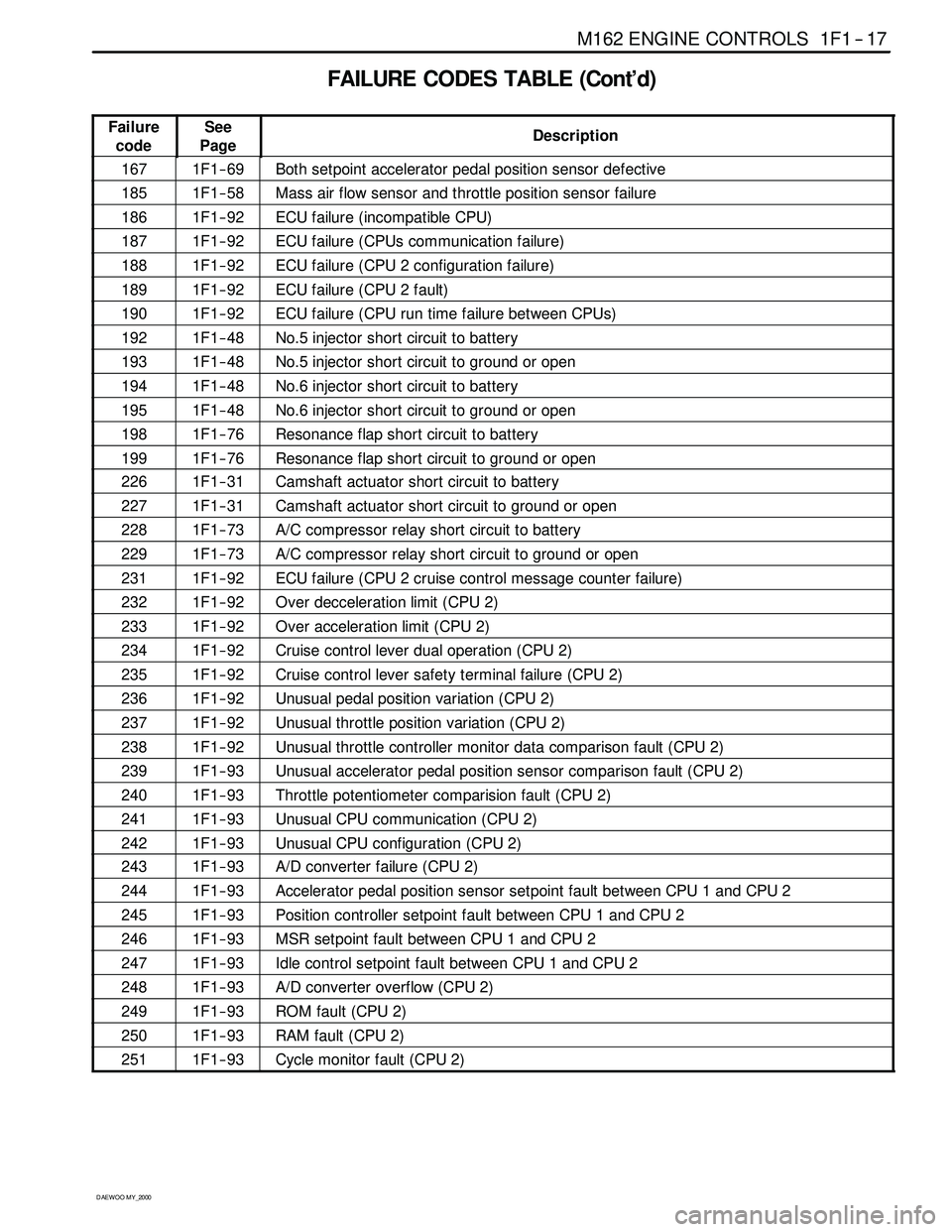
FAILURE CODES TABLE (Cont’d)
Failure
codeSee
PageDescription
1671F1 -- 69Both setpoint accelerator pedal position sensor defective
1851F1 -- 58Mass air flow sensor and throttle position sensor failure
1861F1 -- 92ECU failure (incompatible CPU)
1871F1 -- 92ECU failure (CPUs communication failure)
1881F1 -- 92ECU failure (CPU 2 configuration failure)
1891F1 -- 92ECU failure (CPU 2 fault)
1901F1 -- 92ECU failure (CPU run time failure between CPUs)
1921F1 -- 48No.5 injector short circuit to battery
1931F1 -- 48No.5 injector short circuit to ground or open
1941F1 -- 48No.6 injector short circuit to battery
1951F1 -- 48No.6 injector short circuit to ground or open
1981F1 -- 76Resonance flap short circuit to battery
1991F1 -- 76Resonance flap short circuit to ground or open
2261F1 -- 31Camshaft actuator short circuit to battery
2271F1 -- 31Camshaft actuator short circuit to ground or open
2281F1 -- 73A/C compressor relay short circuit to battery
2291F1 -- 73A/C compressor relay short circuit to ground or open
2311F1 -- 92ECU failure (CPU 2 cruise control message counter failure)
2321F1 -- 92Over decceleration limit (CPU 2)
2331F1 -- 92Over acceleration limit (CPU 2)
2341F1 -- 92Cruise control lever dual operation (CPU 2)
2351F1 -- 92Cruise control lever safety terminal failure (CPU 2)
2361F1 -- 92Unusual pedal position variation (CPU 2)
2371F1 -- 92Unusual throttle position variation (CPU 2)
2381F1 -- 92Unusual throttle controller monitor data comparison fault (CPU 2)
2391F1 -- 93Unusual accelerator pedal position sensor comparison fault (CPU 2)
2401F1 -- 93Throttle potentiometer comparision fault (CPU 2)
2411F1 -- 93Unusual CPU communication (CPU 2)
2421F1 -- 93Unusual CPU configuration (CPU 2)
2431F1 -- 93A/D converter failure (CPU 2)
2441F1 -- 93Accelerator pedal position sensor setpoint fault between CPU 1 and CPU 2
2451F1 -- 93Position controller setpoint fault between CPU 1 and CPU 2
2461F1 -- 93MSR setpoint fault between CPU 1 and CPU 2
2471F1 -- 93Idle control setpoint fault between CPU 1 and CPU 2
2481F1 -- 93A/Dconverteroverflow(CPU2)
2491F1 -- 93ROM fault (CPU 2)
2501F1 -- 93RAM fault (CPU 2)
2511F1 -- 93Cycle monitor fault (CPU 2)