brake SSANGYONG KORANDO 1997 Service User Guide
[x] Cancel search | Manufacturer: SSANGYONG, Model Year: 1997, Model line: KORANDO, Model: SSANGYONG KORANDO 1997Pages: 2053, PDF Size: 88.33 MB
Page 166 of 2053

M162 ENGINE CONTROLS 1F1 -- 3
D AEW OO M Y_2000
SPECIFICATIONS
ENGINE DATA DISPLAY TABLE
ParameterUnitVa l u e
Engine Coolant Temp.°Cgreater than 95_Cafterwarmup
Intake Air Temp.°C-- 40 ~ 130_C (varies with ambient
temp. or engine mode)
Engine RPMrpm700±50 (P/N), 600±50 (D)
Regular RPMrpm700±50 (P/N), 600±50 (D)
Engine Load%18 ~ 25 %
Mass Air Flow MeterKg/h16 ~ 25 Kg/h
Throttle Position Angle_TA0_TA(upto100_TA at the wide
open throttle)
Spark Advance_CA8_CA (6 ~ 9_CA)
Indicated Engine TorqueNmVaries with engine condition
Injection Timems3~5ms
Battery VoltageV13.5 ~ 14.1 v (engine running)
Front Axle SpeedKm/h0~265Km/h
Rear Axle SpeedKm/h0~265Km/h
Accel. Pedal Position 1V0.4~4.8V
Accel. Pedal Position 2V0.2~2.4V
Throttle Position 1V0.3~4.6V
Throttle Position 2V0.3~4.6V
Fuel Integrator0.8 ~ 1.2
Oxygen Sensormv100 ~ 900 mv
A/C S/W Condition1=ON/0=OFF--
Full Load State1=ON/0=OFF--
Shift Gear State (A/T)1=ON/0=OFF--
A/CControlState1=ON/0=OFF--
Clutch Switch (M/T)1=ON/0=OFF--
Cam Actuator State1=ON/0=OFF--
Knocking Control1=ON/0=OFF--
Protect Mission1=ON/0=OFF--
Purge Control Valve1=ON/0=OFF--
Lambda Function1=ON/0=OFF--
Catalyst Heating1=ON/0=OFF--
Overrun Fuel Cut1=ON/0=OFF--
Full Fuel Cut1=ON/0=OFF--
Brake Switch1=ON/0=OFF--
Cruise Control Status1=ON/0=OFF--
* Condition : Warmed up, idle, P/N or neutral
Page 238 of 2053

M162 ENGINE CONTROLS 1F1 -- 75
D AEW OO M Y_2000
TRACTION CONTROLSYSTEM (TCS)
KAB1F310
Failure
CodeDescriptionTrouble AreaMaintenance Hint
150TCS input signal short
circuit to batteryTCS short circuit to powerDInspection the Engine Control Module
(ECM) pin 45 about short circuit or
openwithbadcontact
151TCS input signal short
circuit to ground or openTCS short circuit to ground or
open
openwithbadcontact
DInspection the TCS lamp of I/P cluster.
DInspection the ECM
Circuit Description
Battery voltage is supplied to the TCS warning lamp with the ignition in ON and START. The warning lamp can be
activated only by the Electrical Brake Control Module (EBCM) internally supplying ground to terminal 32. If the TCS
input circuit is open or short, this failure codewill be set.
Page 240 of 2053

M162 ENGINE CONTROLS 1F1 -- 77
D AEW OO M Y_2000
STOP LAMP SWITCH
KAB1F320
Failure
CodeDescriptionTrouble AreaMaintenance Hint
135Stop lamp switch failure
When malfunction of stop
lamp switch – implausible
condition of stop lamp signal
input
DMonitoring the actual operational
status and vehicle speed signal
through scan tool
DInspection the Engine Control Module
(ECM) pin 49 about short circuit or
open with bad contact
DInspection the contact condition of
stop lamp switch
DInspection the ECM
Circuit Description
The stop lamp switch is normally opened. When the ignition switch ON and brake ON, the battery voltage is supplied to
the ECM. A scan tool should display ON when brake pedal is depressed and should read OFF with brake pedal rele-
ased.
Page 271 of 2053

M162 ENGINE INTAKE & EXHAUST 1G1 -- 3
D AEW OO M Y_2000
MAINTENANCE AND REPAIR
ON -- VEHICLE SERVICE
AIR CLEANER
1 Element Assembly
2 Cleaner Assembly -- Air
3 Shield Cover -- Air Intake4 Shield Assembly -- Air Intake
5 Braket Assembly -- Air Cleaner Mounting
6 Braket Assembly -- Shield Surport
Page 276 of 2053
1G1 -- 8 M162 ENGINE INTAKE & EXHAUST
D AEW OO M Y_2000
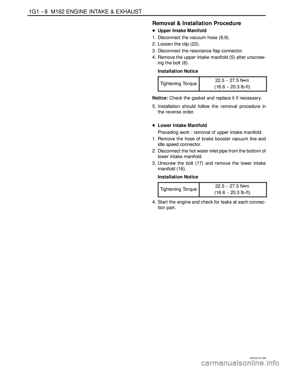
Removal & Installation Procedure
DUpper Intake Manifold
1. Disconnect the vacuum hose (8,9).
2. Loosen the clip (22).
3. Disconnect the resonance flap connector.
4. Remove the upper intake manifold (5) after unscrew-
ing the bolt (6).
Installation Notice
Tightening Torque
22.5 -- 27.5 NSm
(16.6 -- 20.3 lb-ft)
Notice:Check the gasket and replace it if necessary.
5. Installation should follow the removal procedure in
the reverse order.
DLower Intake Manifold
Preceding work : removal of upper intake manifold
1. Remove the hose of brake booster vacuum line and
idle speed connector.
2. Disconnect the hot water inlet pipe from the bottom of
lower intake manifold.
3. Unscrew the bolt (17) and remove the lower intake
manifold (16).
Installation Notice
Tightening Torque
22.5 -- 27.5 NSm
(16.6 -- 20.3 lb-ft)
4. Start the engine and check for leaks at each connec-
tion part.
Page 293 of 2053

1A2 -- 10 GENERAL ENGINE INFORMATION
D AEW OO M Y_2000
Measuring Procedure
1. Warm the engine up to normal operating tempera-
ture.
2. Remove the spark plugs.
3. Place the diagram sheet to compression pressure
tester.
4. Connect the adaptor to compression pressure tester
and install it into the spark plug hole.
5. Crank the engine approx. eight revolutions by using
the start motor.6. Compare the measurements of compression pres-
sure tester with the specifications.
7. Measure the compression pressure of the other cylin-
ders in the same way.
8. If measured value is not within the specifications, per-
form the cylinder pressure leakage test.
Notice
DDischarge the combustion residues in the cylinders
before testing the compression pressure.
DApply the parking brake before cranking the engine.
Page 305 of 2053

1B2 -- 12 M161 ENGINE MECHANICAL
D AEW OO M Y_2000
21. Separate the hose toward engine from canister
purge solenoid valve and canister. Refer toSection
1F2, Engine Control.
22. Remove the automatic transmission oil cooler line
retaining bolts from the automatic transmission side
and oil pan side.
23. Remove the automatic transmission oil cooler line
retaining bolts from engine side and oil pan side.
24. Separate the vacuum hose for brake booster.
25. Separate the other vacuum hoses.
26. By rotating the crankshaft from the front of engine,
remove the 6 torque converter mounting bolts from
the engine ring gear plate.
Installation Notice
Tightening Torque
42 NSm (31 lb-ft)
Page 425 of 2053

M161 ENGINE CONTROLS 1F2 -- 3
D AEW OO M Y_2000
SPECIFICATIONS
ENGINE DATA DISPLAY TABLE
ParameterUnitVa l u e
Engine Coolant Temp.°Cgreater than 95_Cafterwarmup
Intake Air Temp.°C-- 40 ~ 130_C (varies with ambient
temp. or engine mode)
Engine RPMrpm700±50 (P/N), 600±50 (D)
Regular RPMrpm700±50 (P/N), 600±50 (D)
Engine Load%18 ~ 25 %
Mass Air Flow MeterKg/h16 ~ 25 Kg/h
Throttle Position Angle_TA0_TA(upto100_TA at the wide
open throttle)
Spark Advance_CA8_CA (6 ~ 9_CA)
Indicated Engine TorqueNmVaries with engine condition
Injection Timems3~5ms
Battery VoltageV13.5 ~ 14.1 v (engine running)
Front Axle SpeedKm/h0~265Km/h
Rear Axle SpeedKm/h0~265Km/h
Accel. Pedal Position 1V0.4~4.8V
Accel. Pedal Position 2V0.2~2.4V
Throttle Position 1V0.3~4.6V
Throttle Position 2V0.3~4.6V
Fuel Integrator0.8 ~ 1.2
Oxygen Sensormv100 ~ 900 mv
A/C S/W Condition1=ON/0=OFF--
Full Load State1=ON/0=OFF--
Shift Gear State (A/T)1=ON/0=OFF--
A/CControlState1=ON/0=OFF--
Clutch Switch (M/T)1=ON/0=OFF--
Cam Actuator State1=ON/0=OFF--
Knocking Control1=ON/0=OFF--
Protect Mission1=ON/0=OFF--
Purge Control Valve1=ON/0=OFF--
Lambda Function1=ON/0=OFF--
Catalyst Heating1=ON/0=OFF--
Overrun Fuel Cut1=ON/0=OFF--
Full Fuel Cut1=ON/0=OFF--
Brake Switch1=ON/0=OFF--
Cruise Control Status1=ON/0=OFF--
* Condition : Warmed up, idle, P/N or neutral
Page 493 of 2053

M161 ENGINE CONTROLS 1F2 -- 75
D AEW OO M Y_2000
TRACTION CONTROLSYSTEM (TCS)
KAB1F310
Failure
CodeDescriptionTrouble AreaMaintenance Hint
150TCS input signal short
circuit to batteryTCS short circuit to powerDInspection the Engine Control Module
(ECM) pin 45 about short circuit or
openwithbadcontact
151TCS input signal short
circuit to ground or openTCS short circuit to ground or
open
openwithbadcontact
DInspection the TCS lamp of I/P cluster.
DInspection the ECM
Circuit Description
Battery voltage is supplied to the TCS warning lamp with the ignition in ON and START. The warning lamp can be
activated only by the Electrical Brake Control Module (EBCM) internally supplying ground to terminal 32. If the TCS
input circuit is open or short, this failure codewill be set.
Page 494 of 2053

1F2 -- 76 M161 ENGINE CONTROLS
D AEW OO M Y_2000
STOP LAMP SWITCH
KAB1F320
Failure
CodeDescriptionTrouble AreaMaintenance Hint
135Stop lamp switch failure
When malfunction of stop
lamp switch – implausible
condition of stop lamp signal
input
DMonitoring the actual operational
status and vehicle speed signal
through scan tool
DInspection the Engine Control Module
(ECM) pin 49 about short circuit or
open with bad contact
DInspection the contact condition of
stop lamp switch
DInspection the ECM
Circuit Description
The stop lamp switch is normally opened. When the ignition switch ON and brake ON, the battery voltage is supplied to
the ECM. A scan tool should display ON when brake pedal is depressed and should read OFF with brake pedal rele-
ased.