sensor SSANGYONG KORANDO 1997 Service Repair Manual
[x] Cancel search | Manufacturer: SSANGYONG, Model Year: 1997, Model line: KORANDO, Model: SSANGYONG KORANDO 1997Pages: 2053, PDF Size: 88.33 MB
Page 23 of 2053

GENERAL ENGINE INFORMATION 1A1 -- 3
D AEW OO M Y_2000
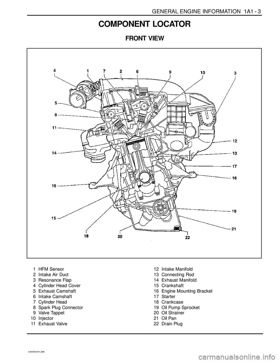
COMPONENT LOCATOR
FRONT VIEW
1 HFM Sensor
2 Intake Air Duct
3 Resonance Flap
4 Cylinder Head Cover
5 Exhaust Camshaft
6 Intake Camshaft
7 Cylinder Head
8 Spark Plug Connector
9 Valve Tappet
10 Injector
11 Exhaust Valve12 Intake Manifold
13 Connecting Rod
14 Exhaust Manifold
15 Crankshaft
16 Engine Mounting Bracket
17 Starter
18 Crankcase
19 Oil Pump Sprocket
20 Oil Strainer
21 Oil Pan
22 Drain Plug
Page 40 of 2053

1B1 -- 8 M162 ENGINE MECHANICAL
D AEW OO M Y_2000
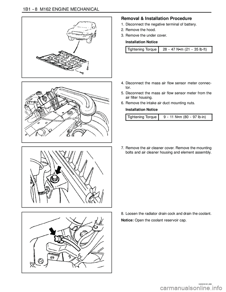
Removal & Installation Procedure
1. Disconnect the negative terminal of battery.
2. Remove the hood.
3. Remove the under cover.
Installation Notice
Tightening Torque
28 -- 47 NSm (21 -- 35 lb-ft)
4. Disconnect the mass air flow sensor meter connec-
tor.
5. Disconnect the mass air flow sensor meter from the
air filter housing.
6. Remove the intake air duct mounting nuts.
Installation Notice
Tightening Torque
9--11NSm (80 -- 97 lb-in)
7. Remove the air cleaner cover. Remove the mounting
bolts and air cleaner housing and element assembly.
8. Loosen the radiator drain cock and drain the coolant.
Notice:Open the coolant reservoir cap.
Page 43 of 2053

M162 ENGINE MECHANICAL 1B1 -- 11
D AEW OO M Y_2000
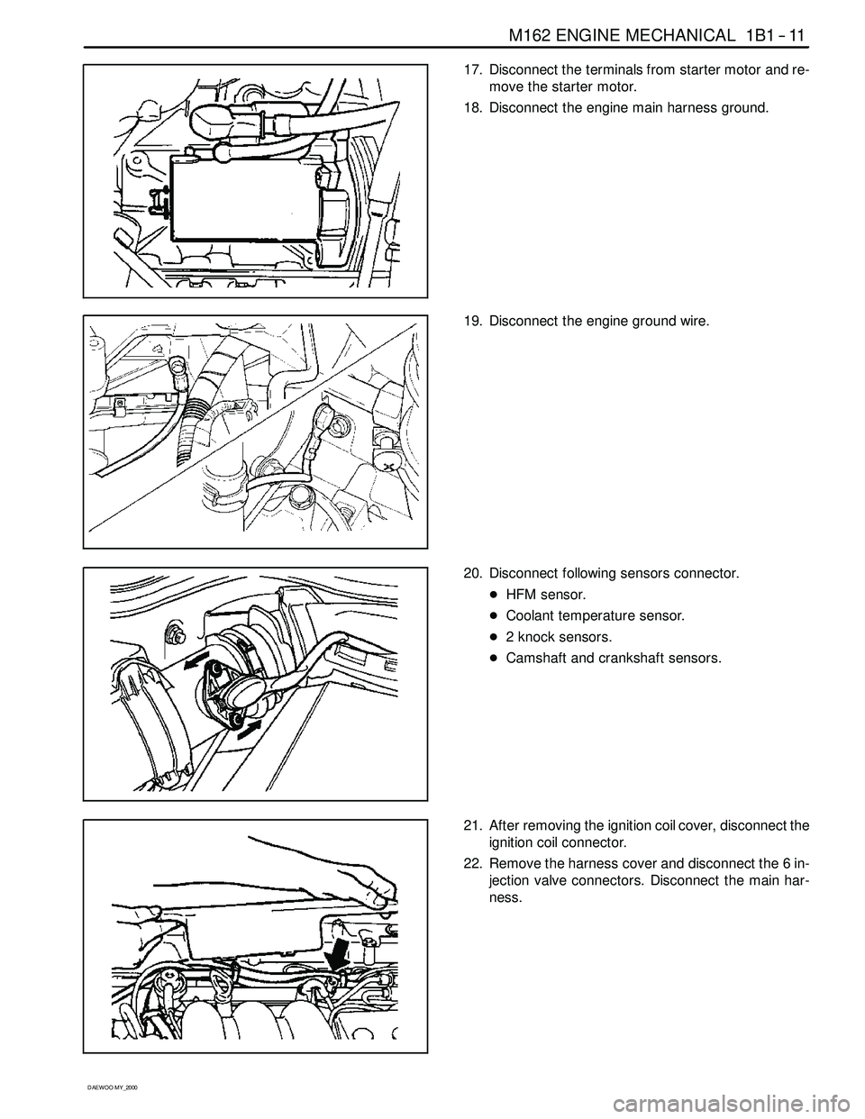
17. Disconnect the terminals from starter motor and re-
move the starter motor.
18. Disconnect the engine main harness ground.
19. Disconnect the engine ground wire.
20. Disconnect following sensors connector.
DHFM sensor.
DCoolant temperature sensor.
D2 knock sensors.
DCamshaft and crankshaft sensors.
21. After removing the ignition coil cover, disconnect the
ignition coil connector.
22. Remove the harness cover and disconnect the 6 in-
jection valve connectors. Disconnect the main har-
ness.
Page 58 of 2053

1B1 -- 26 M162 ENGINE MECHANICAL
D AEW OO M Y_2000
CYLINDER HEAD FRONT COVER
Preceding Work: Removal of cylinder head cover
Removal of coolant connection fitting
1 Camshaft Position Sensor
2 Magnet Assembly
3 Upper Guide Rail
4 Bolt (M6 x 60, 3 pieces)
22.5-- 27.5 NSm (16.6-- 20.3 lb-ft) .............5 Bolt (M8 x 80, 3 pieces)
22.5-- 27.5 NSm (16.6--20.3 lb-ft) .............
6 Front Cover
7 Rubber Gasket Replace....................
8 Bolt (M6 x 16, 3 pieces)
9--11 NSm (80-- 97 lb-in) .....................
Page 82 of 2053

1B1 -- 50 M162 ENGINE MECHANICAL
D AEW OO M Y_2000
CAMSHAFT ADJUSTER
Preceding Work: Removal of cylinder head cover
Removal of cylinder head front cover
1 Bolt (M6 x 16, 3 pieces)
9--11 NSm (80-- 97 lb-in) .....................
2 Magnet Assembly (2 Pin Connector)
3Bolt 35NSm (26 lb-ft) ......................
4 Armature
5RollPin
6 Nut (M20 x 1.5) 60-- 70 NSm (44-- 52 lb-ft) ......
7 Front Cover
8 Seal
9 Camshaft Position Sensor
10 Bolt (M6 x 16, 2 pieces)
9--11 NSm (80-- 97 lb-in) .....................
11 Seal12 Seal Cover
13 Camshaft Sprocket and Position Indicator (b)
14 Adjuster Piston
15 Flange bolt (M7 x 13, 3 pieces)
1ststep18--22NSm (13-- 16 lb-ft) ...........
2ndstep60°±5°
16 Flange Shaft
17 Compression Spring
18 Control Piston
19 Circlip
20 Oil Gallery
21 Pin
22 Intake Camshaft
Page 164 of 2053

D AEW OO M Y_2000
SECTION 1F1
ENGINE CONTROLS
CAUTION: Disconnect the negative battery cable before removing or installing any electrical unit or when a
tool or equipment could easily come in contact with exposed electrical terminals. Disconnecting this cable
will help prevent personal injury and damage to the vehicle. The ignition must also be in LOCK unless other -
wise noted.
TABLE OF CONTENTS
Engine and ECM Problem Check Report 1F1 -- 2....
Specifications 1F1 -- 3............................
Engine Data Display Table 1F1 -- 3.................
Fastener Tightening Specifications 1F1 -- 4..........
Fuel System Specification 1F1 -- 5.................
Temperature vs Resistance 1F1 -- 5................
Special Tools and Equipment 1F1 -- 6..............
Special Tools Table 1F1 -- 6.......................
Schematic and Routing Diagrams 1F1 -- 7..........
ECM Wiring Diagram
(3.2L DOHC -- MSE 3.62S) 1F1 -- 7..............
Diagnosis 1F1 -- 14................................
Failure Code Diagnosis 1F1 -- 14.....................
Clearing Failure Codes 1F1 -- 14...................
Failure Codes Table 1F1 -- 14.....................
Ignition System 1F1 -- 18...........................
Ignition Coil 1F1 -- 20.............................
Crankshaft Position (CKP) Sensor 1F1 -- 22.........
Camshaft Position (CMP) Sensor 1F1 -- 26..........
Camshaft Actuator 1F1 -- 30......................
Knock Sensor (KS) 1F1 -- 32......................
Spark Plug 1F1 -- 34.............................
System Voltage 1F1 -- 38.........................
Ignition Switch 1F1 -- 39..........................
Fuel System 1F1 -- 40..............................
Fuel Pump 1F1 -- 42.............................
Fuel Injector 1F1 -- 46............................
Purge Control Valve 1F1 -- 50.....................
Fuel Rail 1F1 -- 52...............................
Fuel Pressure Regulator 1F1 -- 54.................
Induction System 1F1 -- 56..........................
Throttle Valve Actuator 1F1 -- 56...................
Hot Film Air Mass (HFM) Sensor 1F1 -- 60..........
Engine Coolant Temperature (ECT) Sensor 1F1 -- 64.
Accelerator Pedal Module 1F1 -- 68................
Clutch Switch 1F1 -- 71...........................Cooling Fan 1F1 -- 72............................
A/C Compressor Relay 1F1 -- 73...................
Cruise Control Switch 1F1 -- 74....................
Traction Control System (TCS) 1F1 -- 75............
Resonance Flap 1F1 -- 76.........................
Stop Lamp Switch 1F1 -- 77.......................
Engine RPM 1F1 -- 78............................
Exhaust System 1F1 -- 79...........................
Catalytic Converter 1F1 -- 79......................
Oxygen Sensor 1F1 -- 80.........................
Engine Control Module 1F1 -- 86.....................
Serial Data Communication 1F1--88...............
Internal Failure 1F1 -- 90..........................
Electronic Throttle Controller Safety
Malfunction 1F1 -- 92...........................
Immobilizer 1F1 -- 94.............................
Maintenance and Repair 1F1 -- 95..................
On -- Vehicle Service 1F1 -- 95........................
Discharging the Pressure in Fuel System 1F1 -- 95...
Fuel Pump 1F1 -- 95.............................
Fuel Filter 1F1 -- 96..............................
Fuel Tank 1F1 -- 97..............................
Fuel Pressure Regulator 1F1 -- 98.................
Fuel Rail and Injector 1F1 -- 99....................
Engine Coolant Temperature Sensor 1F1 -- 100......
Throttle Body (Integrated with the
Actuator) 1F1 -- 101............................
Hot Film Air Mass (HFM) Sensor 1F1 -- 102.........
Knock Sensor 1F1 -- 102..........................
Pedal Position Sensor 1F1 -- 103...................
Oxygen Sensor 1F1 -- 103........................
Purge Control Valve 1F1 -- 104....................
Canister 1F1 -- 104...............................
Camshaft Position Sensor 1F1 -- 104...............
Crankshaft Position Sensor 1F1 -- 105..............
Engine Control Module 1F1 -- 105..................
Page 166 of 2053

M162 ENGINE CONTROLS 1F1 -- 3
D AEW OO M Y_2000
SPECIFICATIONS
ENGINE DATA DISPLAY TABLE
ParameterUnitVa l u e
Engine Coolant Temp.°Cgreater than 95_Cafterwarmup
Intake Air Temp.°C-- 40 ~ 130_C (varies with ambient
temp. or engine mode)
Engine RPMrpm700±50 (P/N), 600±50 (D)
Regular RPMrpm700±50 (P/N), 600±50 (D)
Engine Load%18 ~ 25 %
Mass Air Flow MeterKg/h16 ~ 25 Kg/h
Throttle Position Angle_TA0_TA(upto100_TA at the wide
open throttle)
Spark Advance_CA8_CA (6 ~ 9_CA)
Indicated Engine TorqueNmVaries with engine condition
Injection Timems3~5ms
Battery VoltageV13.5 ~ 14.1 v (engine running)
Front Axle SpeedKm/h0~265Km/h
Rear Axle SpeedKm/h0~265Km/h
Accel. Pedal Position 1V0.4~4.8V
Accel. Pedal Position 2V0.2~2.4V
Throttle Position 1V0.3~4.6V
Throttle Position 2V0.3~4.6V
Fuel Integrator0.8 ~ 1.2
Oxygen Sensormv100 ~ 900 mv
A/C S/W Condition1=ON/0=OFF--
Full Load State1=ON/0=OFF--
Shift Gear State (A/T)1=ON/0=OFF--
A/CControlState1=ON/0=OFF--
Clutch Switch (M/T)1=ON/0=OFF--
Cam Actuator State1=ON/0=OFF--
Knocking Control1=ON/0=OFF--
Protect Mission1=ON/0=OFF--
Purge Control Valve1=ON/0=OFF--
Lambda Function1=ON/0=OFF--
Catalyst Heating1=ON/0=OFF--
Overrun Fuel Cut1=ON/0=OFF--
Full Fuel Cut1=ON/0=OFF--
Brake Switch1=ON/0=OFF--
Cruise Control Status1=ON/0=OFF--
* Condition : Warmed up, idle, P/N or neutral
Page 167 of 2053

1F1 -- 4 M162 ENGINE CONTROLS
D AEW OO M Y_2000
FASTENER TIGHTENING SPECIFICATIONS
ApplicationNSmLb-FtLb-In
Camshaft Position Sensor Retaining Bolts10--89
Canister Mounting Bolts6--53
Coolant Temperature Sensor3022--
Crankshaft Position Sensor Retaining Bolt10--89
Engine Control Module (ECM) Mounting Bracket Nuts10--89
Fuel Filter Mounting Bracket Bolt6--53
Fuel Filter Lines2821--
Fuel Pressure Test Connector2518--
Fuel Rail Assembly Bolts2518--
Fuel Return And Supply Lines2317--
Fuel Tank Retaining Nuts3828--
Intake Air Duct Mounting Bolts9--80
Knock Sensor Mounting Bolt2518--
Oxygen Sensor5541--
Pedal Position Censor Mounting Bolts And Nut6--53
Throttle Body Bolts12--106
Page 168 of 2053

M162 ENGINE CONTROLS 1F1 -- 5
D AEW OO M Y_2000
FUEL SYSTEM SPECIFICATION
Use Only Unleaded Fuel Rated at 89
Octane or Higher
Fuel quality and additives contained in fuel have a s ig n if i-
cant effect on power output, drivability, and life of the en-
gine.
Fuel with too low an octane number can cause engine
knock.
Caution: Use of fuel with an octane number lower
than 89 may damage engine and exhaust system.
Notice:To prevent accidental use of leaded fuel, the
nozzles for leaded fuel are larger, andwill not fit the fuel
filler neck of your vehicle.
Do Not Use Methanol
Fuels containing methanol (wood alcohol) should not be
used in vehicle.This type of fuel can reduce vehicle performance and
damage components of the fuel system.
Caution: Use of methanol may damage the fuel sys -
tem.
Vehicle Fueling from Drums or Storage
Containers
For safety reasons (particularly when using noncom-
mercial fueling systems) fuel containers, pumps and
hoses must be properly earthed.
Static electricity build up can occur under certain atmo-
spheric and fuel flow conditions if unearthed hoses, par-
ticularly plastic, are fitted to the fuel-- dispensing pump.
It is therefore recommended that earthed pumps with in-
tegrally earthed hoses be used, and that storage con-
tainers be properly earthed during all noncommercial
fueling operations.
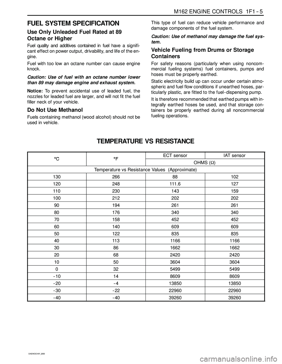
TEMPERATURE VS RESISTANCE
°C°FECT sensorIAT sensor°C°FOHMS (Ω)
Temperature vs Resistance Values (Approximate)
13026688102
120248111. 6127
110230143159
100212202202
90194261261
80176340340
70158452452
60140609609
50122835835
40113116 61166
308616621662
206824202420
105036043604
03254995499
-- 1 01486098609
-- 2 0-- 41385013850
-- 3 0-- 2 22296022960
-- 4 0-- 4 03926039260
Page 177 of 2053

1F1 -- 14 M162 ENGINE CONTROLS
D AEW OO M Y_2000
DIAGNOSIS
FAILURE CODE DIAGNOSIS
CLEARING FAILURE CODES
Notice:To prevent Engine Control Module (ECM) damage, the key must be OFF when disconnecting or reconnecting
the power to the ECM (for example battery cable, ECM pigtail connector, ECM fuse, jumper cables, etc.)
Parameters listed in the table may not be exactly the same as your reading due to the type of instrument or other
factors. If a failure code is displayed during the “TROUBLE CODE” in scan tool check mode, check the circuit for the
code listed in the table below. For details of each code, turn to the page referred to under the “See Page” for the re-
spective “Failure Code” in the below table.
Failure codes should be cleared after repairs have been completed.
FAILURE CODES TABLE
Failure
codeSee
PageDescription
001F1 -- 66Engine coolant temperature sensor low voltage
011F1 -- 66Engine coolant temperature sensor high voltage
021F1 -- 66Engine coolant temperature sensor plausibility
031F1 -- 62Intake air temperature sensor low voltage
041F1 -- 62Intake air temperature sensor high voltage
051F1 -- 62Intake air temperature sensor plausibility
061F1 -- 66Engine coolant temperature insufficient for closed loop fuel control
081F1 -- 38System voltage too low
091F1 -- 62Mass air flow sensor plausibility
101F1 -- 62Mass air flow sensor low voltage
111F1 -- 62Mass air flow sensor high voltage
171F1 -- 23Crankshaft position sensor signal failure (no engine revolution signal)
181F1 -- 23Crankshaft position sensor signal failure (rpm > max. value)
191F1 -- 27Camshaft position senosr signal : No.1 cylinder recognition failure
201F1 -- 23Crankshaft position sensor signal failure (gap recognition failure)
211F1 -- 90Transmission coding failure
231F1 -- 88CAN communication failure : ASR/MSR
241F1 -- 88CAN communication failure : ABS
251F1 -- 94Communication with transponder missing
261F1 -- 88CAN communication failure : TCU (A/T only)
271F1 -- 88CAN communication failure : TOD (E32 only)
291F1 -- 89CAN communication failure : ID 200h not plausible
301F1 -- 89CAN communication failure : ID 208h not plausible
311F1 -- 89CAN communication failure : communication initialization failure
321F1 -- 78Engine rpm output circuit short circuit to battery
331F1 -- 78Engine rpm output circuit short circuit to ground or open
341F1 -- 43Fuel pump relay short circuit to battery
351F1 -- 43Fuel pump relay short circuit to ground or open