cruise control SSANGYONG KORANDO 1997 Service User Guide
[x] Cancel search | Manufacturer: SSANGYONG, Model Year: 1997, Model line: KORANDO, Model: SSANGYONG KORANDO 1997Pages: 2053, PDF Size: 88.33 MB
Page 492 of 2053

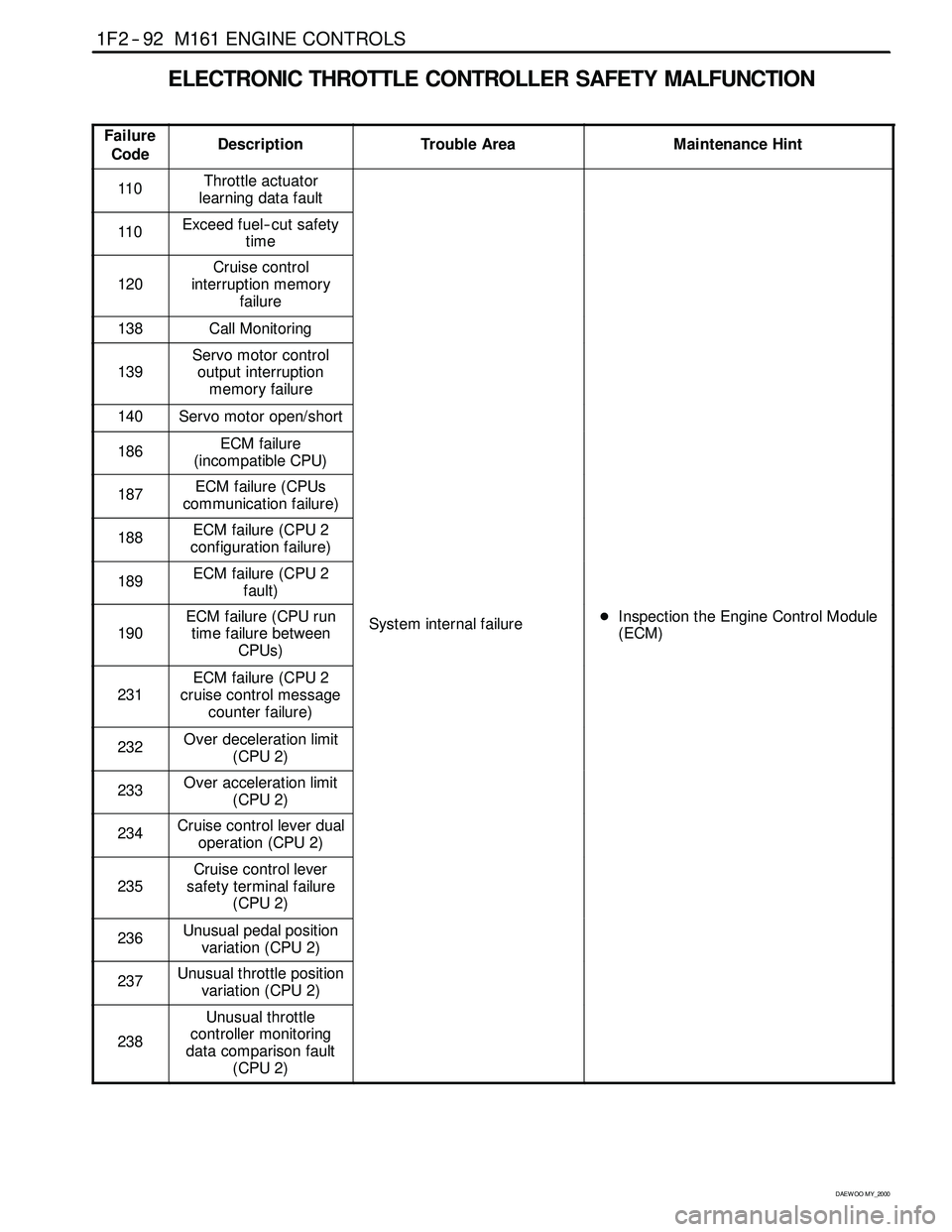
1F2 -- 74 M161 ENGINE CONTROLS
D AEW OO M Y_2000
CRUISE CONTROL SWITCH
KAB1F300
Failure
CodeDescriptionTrouble AreaMaintenance Hint
129
Cruise control “OFF”
due to message counter
failureCruise control system
Message counter fault
130Vehicle speed signal
failureWhen malfunction of
auto-- cruise systemDMonitoring the actual recognition
status and vehicle speed signal
throughscantool
131Vehicle speed signal
failure
autocruisesystem
Implausible condition of
vehicle speed signal.through scan tool
DInspection the Engine Control Module
(ECM)pin52,53,54,55,57about
132Cruise control lever
failureCruise control lever defective
(ECM)pin52,53,54,55,57about
short circuit or open with bad contact
DInspection the CAN and ABS
133Cruise control
acceleration failureCruise control system
Implausible condition of
acceleration signal
InspectiontheCANandABS
DInspection the cruise control lever
switch
DInspection the ECM
134Cruise control
deceleration failureCruise control system
Implausible condition of
deceleration signal
p
Circuit Description
Cruise control is an automatic speed control system that maintain a desired driving speed without using the accelerator
pedal. The vehicle speed must be greater than 40 km/h to engage cruise control.
Page 510 of 2053

1F2 -- 92 M161 ENGINE CONTROLS
D AEW OO M Y_2000
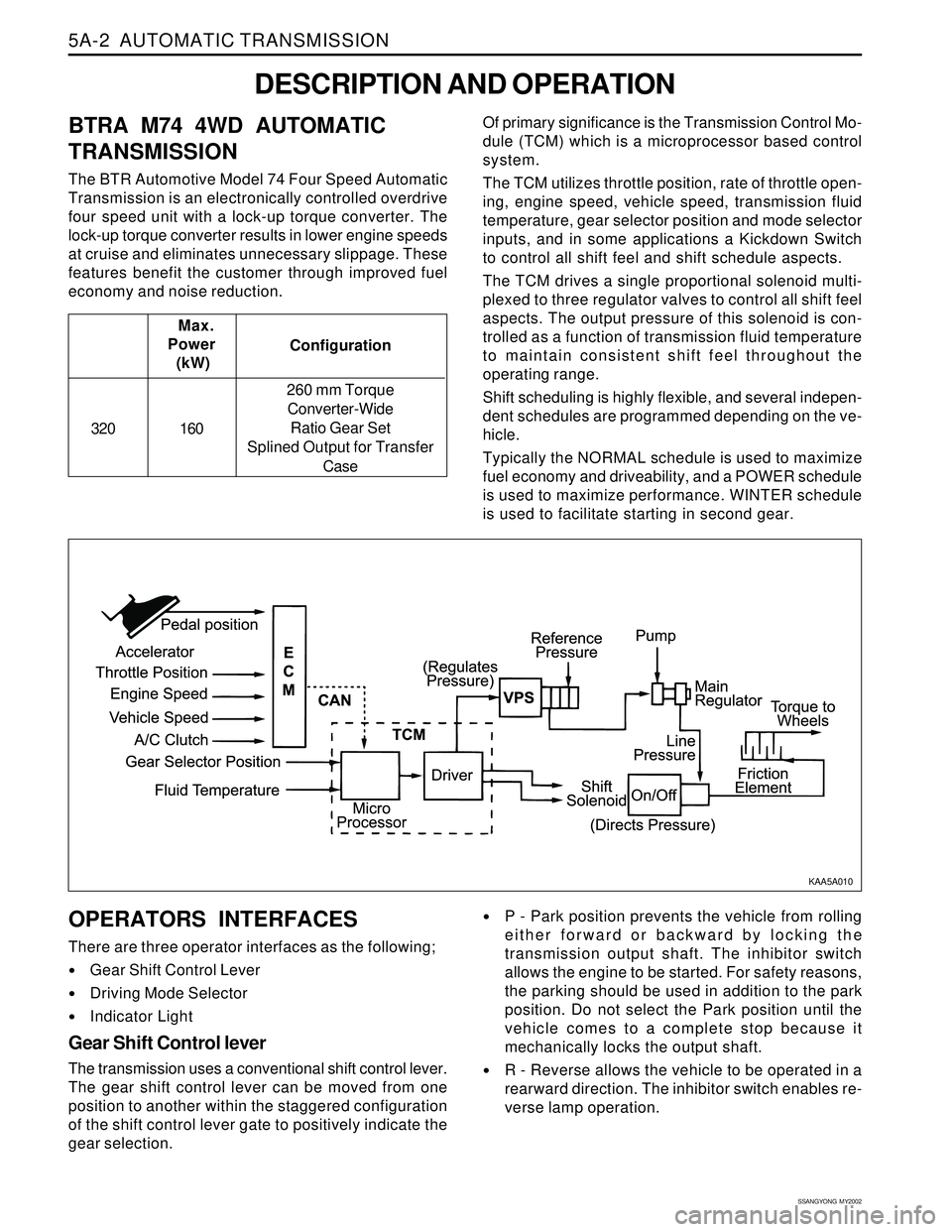
ELECTRONIC THROTTLE CONTROLLER SAFETY MALFUNCTION
Failure
CodeDescriptionTrouble AreaMaintenance Hint
110Throttle actuator
learning data fault
110Exceed fuel-- cut safety
time
120
Cruise control
interruption memory
failure
138Call Monitoring
139
Servo motor control
output interruption
memory failure
140Servo motor open/short
186ECM failure
(incompatible CPU)
187ECM failure (CPUs
communication failure)
188ECM failure (CPU 2
configuration failure)
189ECM failure (CPU 2
fault)
190
ECM failure (CPU run
time failure between
CPUs)System internal failureDInspection the Engine Control Module
(ECM)
231
ECM failure (CPU 2
cruise control message
counter failure)
232Over deceleration limit
(CPU 2)
233Over acceleration limit
(CPU 2)
234Cruise control lever dual
operation (CPU 2)
235
Cruise control lever
safety terminal failure
(CPU 2)
236Unusual pedal position
variation (CPU 2)
237Unusual throttle position
variation (CPU 2)
238
Unusual throttle
controller monitoring
data comparison fault
(CPU 2)
Page 1096 of 2053

5A-2 AUTOMATIC TRANSMISSION
SSANGYONG MY2002
OPERATORS INTERFACES
There are three operator interfaces as the following;
•Gear Shift Control Lever
Driving Mode Selector
Indicator Light
Gear Shift Control lever
The transmission uses a conventional shift control lever.
The gear shift control lever can be moved from one
position to another within the staggered configuration
of the shift control lever gate to positively indicate the
gear selection.
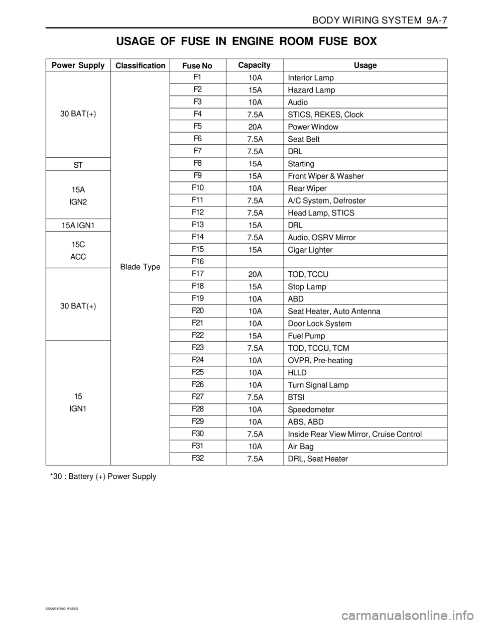
DESCRIPTION AND OPERATION
BTRA M74 4WD AUTOMATIC
TRANSMISSION
The BTR Automotive Model 74 Four Speed Automatic
Transmission is an electronically controlled overdrive
four speed unit with a lock-up torque converter. The
lock-up torque converter results in lower engine speeds
at cruise and eliminates unnecessary slippage. These
features benefit the customer through improved fuel
economy and noise reduction.Of primary significance is the Transmission Control Mo-
dule (TCM) which is a microprocessor based control
system.
The TCM utilizes throttle position, rate of throttle open-
ing, engine speed, vehicle speed, transmission fluid
temperature, gear selector position and mode selector
inputs, and in some applications a Kickdown Switch
to control all shift feel and shift schedule aspects.
The TCM drives a single proportional solenoid multi-
plexed to three regulator valves to control all shift feel
aspects. The output pressure of this solenoid is con-
trolled as a function of transmission fluid temperature
to maintain consistent shift feel throughout the
operating range.
Shift scheduling is highly flexible, and several indepen-
dent schedules are programmed depending on the ve-
hicle.
Typically the NORMAL schedule is used to maximize
fuel economy and driveability, and a POWER schedule
is used to maximize performance. WINTER schedule
is used to facilitate starting in second gear. Configuration Max.
Power
(kW)
320 160260 mm Torque
Converter-Wide
Ratio Gear Set
Splined Output for Transfer
Case
P - Park position prevents the vehicle from rolling
either forward or backward by locking the
transmission output shaft. The inhibitor switch
allows the engine to be started. For safety reasons,
the parking should be used in addition to the park
position. Do not select the Park position until the
vehicle comes to a complete stop because it
mechanically locks the output shaft.
R - Reverse allows the vehicle to be operated in a
rearward direction. The inhibitor switch enables re-
verse lamp operation.
KAA5A010
Page 1494 of 2053

SSANGYONG MY2002
6E-8 POWER STEERING AND COLUMN
Check the ignition switch for damage.
Check the ignition switch for improper installation.
Check the ignition switch electrical connector for
improper installation.ChecksActionReplace the ignition switch.
Remove and inspect the ignition switch. Reinstall the
ignition switch.
Reconnect the ignition switch electrical connector.
Replace the ignition switch electrical connector.
Ignition Switch Will Not Turn
Wiper/Cruise Control Switch Lever
Switch Inoperative: No LOW, HIGH, INTERMITTENT or WASH
Check the wiper switch for damage.
Check the wiper switch for improper installation.
Check the cruise control switch for damage.ChecksActionReplace the wiper/cruise control switch.
Remove and inspect the wiper/cruise control switch.
Reinstall the wiper/cruise control switch.
Replace the wiper/cruise control switch.
Ignition Switch
Electrical System Will Not Function
Check the ignition switch for damage.
Check the ignition switch for improper installation.ChecksActionReplace the ignition switch.
Remove and inspect the ignition switch. Reinstall the
ignition switch.
Page 1658 of 2053

BODY WIRING SYSTEM 9A-7
SSANGYONG MY2002
USAGE OF FUSE IN ENGINE ROOM FUSE BOX
Interior Lamp
Hazard Lamp
Audio
STICS, REKES, Clock
Power Window
Seat Belt
DRL
Starting
Front Wiper & Washer
Rear Wiper
A/C System, Defroster
Head Lamp, STICS
DRL
Audio, OSRV Mirror
Cigar Lighter
TOD, TCCU
Stop Lamp
ABD
Seat Heater, Auto Antenna
Door Lock System
Fuel Pump
TOD, TCCU, TCM
OVPR, Pre-heating
HLLD
Turn Signal Lamp
BTSI
Speedometer
ABS, ABD
Inside Rear View Mirror, Cruise Control
Air Bag
DRL, Seat Heater Power SupplyUsage
Classification
Fuse NoCapacity
30 BAT(+)
ST
15A
IGN2
15A IGN1
15C
ACC
30 BAT(+)
15
IGN1
Blade TypeF1
F2
F3
F4
F5
F6
F7
F8
F9
F10
F11
F12
F13
F14
F15
F16
F17
F18
F19
F20
F21
F22
F23
F24
F25
F26
F27
F28
F29
F30
F31
F3210A
15A
10A
7.5A
20A
7.5A
7.5A
15A
15A
10A
7.5A
7.5A
15A
7.5A
15A
20A
15A
10A
10A
10A
15A
7.5A
10A
10A
10A
7.5A
10A
10A
7.5A
10A
7.5A
*30 : Battery (+) Power Supply
Page 1664 of 2053

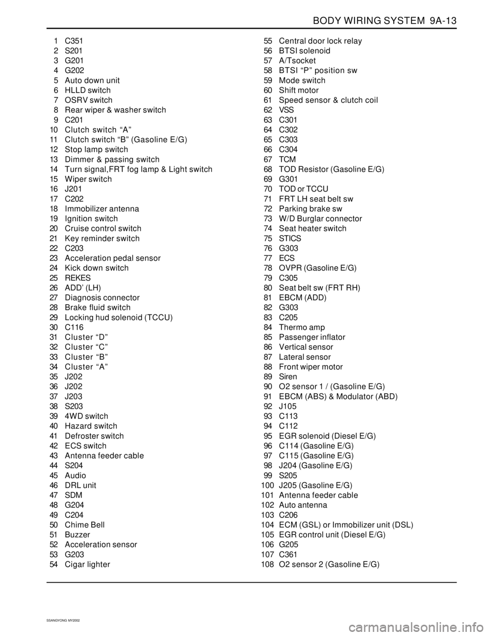
BODY WIRING SYSTEM 9A-13
SSANGYONG MY2002
1 C351
2 S201
3 G201
4 G202
5 Auto down unit
6 HLLD switch
7 OSRV switch
8 Rear wiper & washer switch
9 C201
10 Clutch switch “A”
11 Clutch switch “B” (Gasoline E/G)
12 Stop lamp switch
13 Dimmer & passing switch
14 Turn signal,FRT fog lamp & Light switch
15 Wiper switch
16 J201
17 C202
18 Immobilizer antenna
19 Ignition switch
20 Cruise control switch
21 Key reminder switch
22 C203
23 Acceleration pedal sensor
24 Kick down switch
25 REKES
26 ADD’ (LH)
27 Diagnosis connector
28 Brake fluid switch
29 Locking hud solenoid (TCCU)
30 C116
31 Cluster “D”
32 Cluster “C”
33 Cluster “B”
34 Cluster “A”
35 J202
36 J202
37 J203
38 S203
39 4WD switch
40 Hazard switch
41 Defroster switch
42 ECS switch
43 Antenna feeder cable
44 S204
45 Audio
46 DRL unit
47 SDM
48 G204
49 C204
50 Chime Bell
51 Buzzer
52 Acceleration sensor
53 G203
54 Cigar lighter55 Central door lock relay
56 BTSI solenoid
57 A/Tsocket
58 BTSI “P” position sw
59 Mode switch
60 Shift motor
61 Speed sensor & clutch coil
62 VSS
63 C301
64 C302
65 C303
66 C304
67 TCM
68 TOD Resistor (Gasoline E/G)
69 G301
70 TOD or TCCU
71 FRT LH seat belt sw
72 Parking brake sw
73 W/D Burglar connector
74 Seat heater switch
75 STICS
76 G303
77 ECS
78 OVPR (Gasoline E/G)
79 C305
80 Seat belt sw (FRT RH)
81 EBCM (ADD)
82 G303
83 C205
84 Thermo amp
85 Passenger inflator
86 Vertical sensor
87 Lateral sensor
88 Front wiper motor
89 Siren
90 O2 sensor 1 / (Gasoline E/G)
91 EBCM (ABS) & Modulator (ABD)
92 J105
93 C113
94 C112
95 EGR solenoid (Diesel E/G)
96 C114 (Gasoline E/G)
97 C115 (Gasoline E/G)
98 J204 (Gasoline E/G)
99 S205
100 J205 (Gasoline E/G)
101 Antenna feeder cable
102 Auto antenna
103 C206
104 ECM (GSL) or Immobilizer unit (DSL)
105 EGR control unit (Diesel E/G)
106 G205
107 C361
108 O2 sensor 2 (Gasoline E/G)
Page 1871 of 2053

ELECTRICAL WIRING DIAGRAMS ELECTRICAL WIRING DIAGRAMSELECTRICAL WIRING DIAGRAMS ELECTRICAL WIRING DIAGRAMS
ELECTRICAL WIRING DIAGRAMS
2-7 2-7 2-7 2-7
2-7
2) 2)2) 2)
2)
W/H MAIN W/H MAINW/H MAIN W/H MAIN
W/H MAIN• W/H MAIN
1. C351
2. S201
3. G201
4. G202
5. Auto down unit
6. HLLD switch
7. OSRV switch
8. Rear wiper & washer switch
8-1. DLC9. C201
10. Clutch switch "A"
11. Clutch switch "B" (Gasoline E/G)
12. Stop lamp switch
13. Dimmer & passing switch
14. Turn signal,FRT fog lamp & Light switch
15. Wiper switch
16. J201
17. C20218. Immobilizer antenna
19. Ignition switch
20. Cruise control switch
21. Key reminder switch
22. C203
23. Acceleration pedal sensor
24. Kick down switch
25. REKES
26. ADD' (LH)
27. Diagnosis connector
28. Brake fluid switch
29. Locking hud solenoid (TCCU)
30. C116
31. Cluster "D"
32. Cluster "C"
33. Cluster "B"
34. Cluster "A"
35. J202
36. J202
37. J203
38. S203
39. 4WD switch
40. Hazard switch
41. Defroster switch
42. -
43. Antenna feeder cable
44. S204
45. Audio
46. -
47. SDM
48. G204
49. C204
50. Chime Bell
51. Buzzer
52. Acceleration sensor
53. G203
54. Cigar lighter
55. Central door lock relay
56. BTSI solenoid
57. A/Tsocket
58. BTSI "P" position sw
59. Mode switch
60. Shift motor
61. Speed sensor & clutch coil
62. VSS
63. C301
64. C302
65. C30366. C304
67. TCM
68. TOD Resistor (Gasoline E/G)
69. G301
70. TOD or TCCU
71. FRT LH seat belt sw
72. Parking brake sw
73. W/D Burglar connector
74. Seat heater switch
75. STICS
76. G303
77. -
78. OVPR (Gasoline E/G)
79. C305
80. Seat belt sw (FRT RH)
81. EBCM (ADD)
82. G303
83. C205
84. Thermo amp
85. Passenger inflator
86. -
87. -
88. Front wiper motor
89. Siren
90. O2 sensor 1 / (Gasoline E/G)
91. EBCM (ABS) & Modulator (ABD)
92. J105
93. C113
94. C112
95. EGR solenoid (Diesel E/G)
96. C114 (Gasoline E/G)
97. C115 (Gasoline E/G)
98. J204 (Gasoline E/G)
99. S205
100.J205 (Gasoline E/G)
101.Antenna feeder cable
102.Auto antenna
103.C206
104.ECM (GSL) or Immobilizer unit (DSL)
105.EGR control unit (Diesel E/G)
106. G205
107.C361
108. O2 sensor 2 (Gasoline E/G)
FUSE
BOX
RELAY
BOX
FUSE &
RELAY BOX
A
1011
12131415171618192021222829
30
26
27
31323334
35
3637
38
394041
43
83888990
91
93
9495
9296
979899102
101100
106107
104105
103
108
84
85
44
8-1
4748
49
50
51
52
53
45
55
54565758
60616263
6465
66
67
68
71
72
73
74
7576
78
7980
8182
69
70
59
232425
13
4259678
Page 1893 of 2053

USAGE AND CAPACITY OF FUSES IN FUSE BOX USAGE AND CAPACITY OF FUSES IN FUSE BOX USAGE AND CAPACITY OF FUSES IN FUSE BOX USAGE AND CAPACITY OF FUSES IN FUSE BOX
USAGE AND CAPACITY OF FUSES IN FUSE BOX
4-3 4-34-3 4-3
4-3
2. 2.2. 2.
2.
PASSENGER ROOM FUSE BOX PASSENGER ROOM FUSE BOXPASSENGER ROOM FUSE BOX PASSENGER ROOM FUSE BOX
PASSENGER ROOM FUSE BOX1) 1)1) 1)
1)
POSITION OF FUSE POSITION OF FUSEPOSITION OF FUSE POSITION OF FUSE
POSITION OF FUSE
2) 2)2) 2)
2)
USAGE OF FUSE IN PASSENGER ROOM FUSE BOX USAGE OF FUSE IN PASSENGER ROOM FUSE BOXUSAGE OF FUSE IN PASSENGER ROOM FUSE BOX USAGE OF FUSE IN PASSENGER ROOM FUSE BOX
USAGE OF FUSE IN PASSENGER ROOM FUSE BOX
10A
15A
15A
7.5A
30A
7.5A
-
15A
15A
10A
7.5A
7.5A
-
7.5A
15A
20A
15A
10A
10A
10A
15A
7.5A
10A
7.5A
10A
7.5A
10A
15A
7.5A
10A
7.5A F1
F2
F3
F4
F5
F6
F7
F8
F9
F10
F11
F12
F13
F14
F15
F16
F17
F18
F19
F20
F21
F22
F23
F24
F25
F26
F27
F28
F29
F30
F31
F32
Power Supply Power SupplyPower Supply Power Supply
Power Supply
Classification ClassificationClassification Classification
Classification
Fuse No Fuse NoFuse No Fuse No
Fuse No
Capacity CapacityCapacity Capacity
Capacity
Usage UsageUsage Usage
Usage* 30 : BAT(+) Power Supply Through Ef1.
Blade TypeInterior Lamp, Rr Fog Lp, Cluster
Hazard Lamp
Audio
STICS,REKES,Clock
Power Window
Seat Belt, Diagnosis(DLC)
-
Starting
Front Wiper & Washer
Rear Wiper
A/C System,Defroster
Head Lamp,STICS
-
Audio,OSRV Mirror
Cigar Lighter
TOD,TCCU
Stop Lamp
ABD
Seat Heater,Auto Antenna
Door Lock System
Fuel Pump
TOD,TCCU,TCM
OVPR,EGR
HLLD, B/UP Lamp
Turn Signal Lamp
BTSI, Pre-heating, Shift Lock
Speedometer
ABS,ABD
Inside Rear View Mirror, Cruise Control,
Immobilizer, Cluster
Air Bag
Seat Heater
30 BAT(+)
ST
15A
IGN2
30 BAT(+)15C
ACC 15A IGN1
15
IGN1
Page 1896 of 2053

2) INJECTOR, FUEL PUMP RELAY, FUEL PUMP, IMMOBILIZER ........................................................................ 5-24
(1) W/O EURO III .................................................................................................................................................................................... 5-24
(2) W/ EURO III ....................................................................................................................................................................................... 5-26
3) SENSOR (CAM SHAFT POSITION, MAP, O
2), CAM SHAFT ACTUATOR ...................................................... 5-28
(1) W/O EURO III .................................................................................................................................................................................... 5-28
(2) W/ EURO III ....................................................................................................................................................................................... 5-30
4) SENSOR (ENGINE TEMPERATURE, INTAKE AIR TEMP', KNOCK),
CANISTER PURGE VALVE, DIAGNOSIS........................................................................................................... 5-32
(1) W/O EURO III .................................................................................................................................................................................... 5-32
(2) W/ EURO III ....................................................................................................................................................................................... 5-34
5) VEHICLE SPEED SENSOR, SWITCH (CRUISE CONTROL, STOP LAMP, INHIBITOR, CLUTCH) ............. 5-36
6. 6. 6. 6.
6.
ECM (ELECTRONIC CONTROL MODULE) : E32 MSE ECM (ELECTRONIC CONTROL MODULE) : E32 MSEECM (ELECTRONIC CONTROL MODULE) : E32 MSE ECM (ELECTRONIC CONTROL MODULE) : E32 MSE
ECM (ELECTRONIC CONTROL MODULE) : E32 MSE
......................................................... .................................................................................................................. .........................................................
.........................................................
5-38 5-38 5-38 5-38
5-38
1) SENSOR (CRANK SHAFT POSITION, ACCELERATION PEDAL), THROTTLE MOTOR.......................................
& SENSOR, IGNTION COIL & SPARK PLUG .................................................................................................... 5-38
2) INJECTOR, FUEL PUMP RELAY, FUEL PUMP, IMMOBILIZER ........................................................................ 5-40
(1) W/O EURO III .................................................................................................................................................................................... 5-40
(2) W/ EURO III ....................................................................................................................................................................................... 5-42
3) SENSOR (CAM SHAFT POSITION, AIR FLOW), INTAKE MANIFOLD RESONANCE ............................................
FLAP, CAM SHAFT ACTUATOR, FUEL GAUGE................................................................................................ 5-44
(1) W/O EURO III .................................................................................................................................................................................... 5-44
(2) W/ EURO III ....................................................................................................................................................................................... 5-46
4) SENSOR (ENGINE TEMPERATURE, KNOCK1, KNOCK2), CANISTER PURGE VALVE, DIAGNOSIS....... 5-48
5) VEHICLE SPEED SENSOR, SWITCH (CRUISE CONTROL, STOP LAMP, INHIBITOR, CLUTCH) ............. 5-50
6) O
2 SENSOR (1,2,3,4) ............................................................................................................................................. 5-52
7. 7. 7. 7.
7.
TCM (TRASMISSION CONTROL MODULE) - DIESEL TCM (TRASMISSION CONTROL MODULE) - DIESELTCM (TRASMISSION CONTROL MODULE) - DIESEL TCM (TRASMISSION CONTROL MODULE) - DIESEL
TCM (TRASMISSION CONTROL MODULE) - DIESEL
........................................................... ...................................................................................................................... ...........................................................
...........................................................
5-54 5-54 5-54 5-54
5-54
1) MODE SWITCH, INDICATOR, DIAGNOSIS........................................................................................................ 5-54
2) TRANSMISSION, INDICATOR, T/M LEVER, KICK DOWN SWITCH............................................................... 5-56
8. 8. 8. 8.
8.
TCM (TRASMISSION CONTROL MODULE) - GASOLINE TCM (TRASMISSION CONTROL MODULE) - GASOLINETCM (TRASMISSION CONTROL MODULE) - GASOLINE TCM (TRASMISSION CONTROL MODULE) - GASOLINE
TCM (TRASMISSION CONTROL MODULE) - GASOLINE
..................................................... .......................................................................................................... .....................................................
.....................................................
5-58 5-58 5-58 5-58
5-58
1) MODE SWITCH, INDICATOR, DIAGNOSIS........................................................................................................ 5-58
2) TRANSMISSION, INDICATOR, T/M LEVER, KICK DOWN SWITCH............................................................... 5-60
Page 1930 of 2053

5-36 5-36 5-36 5-36
5-36
ELECTRICAL WIRING DIAGRAMS ELECTRICAL WIRING DIAGRAMSELECTRICAL WIRING DIAGRAMS ELECTRICAL WIRING DIAGRAMS
ELECTRICAL WIRING DIAGRAMS5) 5)5) 5)
5)
VEHICLE SPEED SENSOR, SWITCH (CRUISE CONTROL, STOP LAMP, VEHICLE SPEED SENSOR, SWITCH (CRUISE CONTROL, STOP LAMP,VEHICLE SPEED SENSOR, SWITCH (CRUISE CONTROL, STOP LAMP, VEHICLE SPEED SENSOR, SWITCH (CRUISE CONTROL, STOP LAMP,
VEHICLE SPEED SENSOR, SWITCH (CRUISE CONTROL, STOP LAMP,
INHIBITOR, CLUTCH) INHIBITOR, CLUTCH)INHIBITOR, CLUTCH) INHIBITOR, CLUTCH)
INHIBITOR, CLUTCH)
a. a.a. a.
a.
CONNECTOR INFORMATION CONNECTOR INFORMATIONCONNECTOR INFORMATION CONNECTOR INFORMATION
CONNECTOR INFORMATIONC104 (8Pin, Colorless)
C206 (6Pin, Black)
C301 (16Pin, Black)
S202 (20Pin,Black)
J202
G201
G202
G205CONNECTOR(NUMBER) CONNECTOR(NUMBER)CONNECTOR(NUMBER) CONNECTOR(NUMBER)
CONNECTOR(NUMBER)
CONNECTING. WIRING HARNESS CONNECTING. WIRING HARNESSCONNECTING. WIRING HARNESS CONNECTING. WIRING HARNESS
CONNECTING. WIRING HARNESS
CONNECTOR POSITION CONNECTOR POSITIONCONNECTOR POSITION CONNECTOR POSITION
CONNECTOR POSITION
Engine Room Fuse Box - W/H Main
W/H Main - W/H ECM Main
W/H Main - W/H Transmission
W/H Main
W/H Main
W/H Main
W/H Main
W/H MainEngine Room Fuse Box
Lower "A" Piller (Upper ECM)
Upper Transfer Case
Behind Cluster
Behind Cluster
Upper Front Left Leg Room
Upper Front Left Leg Room
Center "A" Piller Front Right
b. b.b. b.
b.
CONNECTOR IDENTIFICATION SYMBOL & PIN NUMBER POSITION CONNECTOR IDENTIFICATION SYMBOL & PIN NUMBER POSITIONCONNECTOR IDENTIFICATION SYMBOL & PIN NUMBER POSITION CONNECTOR IDENTIFICATION SYMBOL & PIN NUMBER POSITION
CONNECTOR IDENTIFICATION SYMBOL & PIN NUMBER POSITION
ECM
CRUISE
CONTROL SW
VSS
C206 (BLACK)
INGIBITOR SW
STOP LAMP
SW "B" STOP LAMP
SW "A"
CLUSTER "B"
CLUSTER "A"
CLUSTER "C" CLUSTER "D"
C301 (BLACK)