heating SSANGYONG KORANDO 1997 Service User Guide
[x] Cancel search | Manufacturer: SSANGYONG, Model Year: 1997, Model line: KORANDO, Model: SSANGYONG KORANDO 1997Pages: 2053, PDF Size: 88.33 MB
Page 478 of 2053

1F2 -- 60 M161 ENGINE CONTROLS
D AEW OO M Y_2000
HOT FILM AIR MASS (HFM) SENSOR
YAA1F570
The Hot Film Air Mass (HFM) sensor with recognition of flow direction related to pulsating flow is designed for record-
ing load on Engine Control Module (ECM) by measuring the output voltage proportional to the reference voltage of the
ECM.
Mass Air Flow Sensor
Mass Air Flow (MAF) is a thermal flow meter whose sensor element with its temperature sensors and heating area is
exposed to the MAF to be measured. A heating area located in the center of a thin membrane is controlled to an over --
temperature by a heating resistor and a temperature sensor of this membrane. And the value of over -- temperature
depends on the temperature of the in-- flowing air.
Two temperature sensors on upstream and downstream of the heating area show the same temperature without in-
coming flow. With incoming flow, upstream part is cooled down but downstream temperature retains its temperature
more or less due to the air heated up in the heating area. This temperature difference in quantity and direction depends
on the direction of the incoming flow.
ECM modulates the flow of heating current to maintain the temperature differential between the heated film and the
intake air at a constant level. The amount of heating current required to maintain the temperature thus provides an
index for the MAF. This concept automatically compensates for variations in air density, as this is one of the factors that
determines the amount of warmth that the surrounding air absorbs from the heated element. MAF sensor is located
between the air filter and the throttle valve.
Under high fuel demands, the MAF sensor reads a high mass flow condition, such as Wide Open Throttle (WOT). The
ECM uses this information to enrich the mixture, thus increasing the fuel injector on-- time, to provide the correct
amount of fuel. When decelerating, the mass flow decreases. This mass flow change is sensed by the MAF sensor
and read by the ECM, which then decreases the fuel injector on-- time due to the low fuel demand conditions.
To facilitate the installation of the HFM in the intake passage, lubricating agents may be used. However, when lubri-
cants are used care must be taken to ensure that they do not enter the flow passage and cannot be sucked in with the
air flow.
Page 480 of 2053

1F2 -- 62 M161 ENGINE CONTROLS
D AEW OO M Y_2000
KAB1F250
Failure
CodeDescriptionTrouble AreaMaintenance Hint
03Intake air temperature
sensor low voltageIAT sensor short circuit to
ground or openDMonitoring the actual air temperature
throu
gh scan tool
04Intake air temperature
sensor high voltageIAT sensor short circuit to
power
throughscantool
DInspection the ECM pin 80, 79 about
short circuit or open with bad contact
05Intake air temperature
sensor plausibilityMalfunction in recognition of
IAT
When functional problem
p
DInspection the IAT sensor (integrated
in HFM sensor)
DInspection the ECM
09Mass air flow sensor
plausibilityMalfunction in recognition of
MAF
When air mass not plausibleDMonitoring the actual air mass flow
through scan tool
DIns
pection the ECMpin 81, 105 about
10Mass air flow sensor low
voltageMAF sensor short circuit to
ground or open
DInspectiontheECMpin81,105about
short circuit or open with bad contact
DInspection the MAF sensor (integrated
iHFM)
11Mass air flow sensor
high voltageMAF sensor short circuit to
powerin HFM sensor)
DInspection the ECM
Circuit Description
The heated element on the MAF is a platinum film resistor (heater). It is located on a ceramic plate together with the
other elements in the bridge circuit. The temperature sensitive resistor (flow sensor) also included in the bridge. The
separation of heater and flow sensor facilitates design of the control circuitry. Saw cuts are employed to ensure thermal
decoupling between the heating element and the intake air temperature (IAT) sensor. The complete control circuitry is
located on a single layer. The voltage at the heater provides the index for the mass air flow. The MAF’s electronic
circuitry then converts the voltage to a level suitable for processing in the ECM. This device does not need a burn off
process to maintain its measuring precision over an extended period. In recognition of the fact that most deposits
collect on the sensor element’s leading edge, the essential thermal transfer elements are located downstream on the
ceramic layer. The sensor element is also design to ensure that depositswill not influence the flow pattern around the
sensor.
The IAT sensor uses a thermistor to control the signal voltage to the ECM. The ECM supplies 5 volt reference and a
ground to the sensor. When the air is cold, the resistance is high; therefore the IAT signal voltagewill be high. If the
intake air is warm, resistance is low; therefore the IAT signal voltagewill be low.
Page 500 of 2053
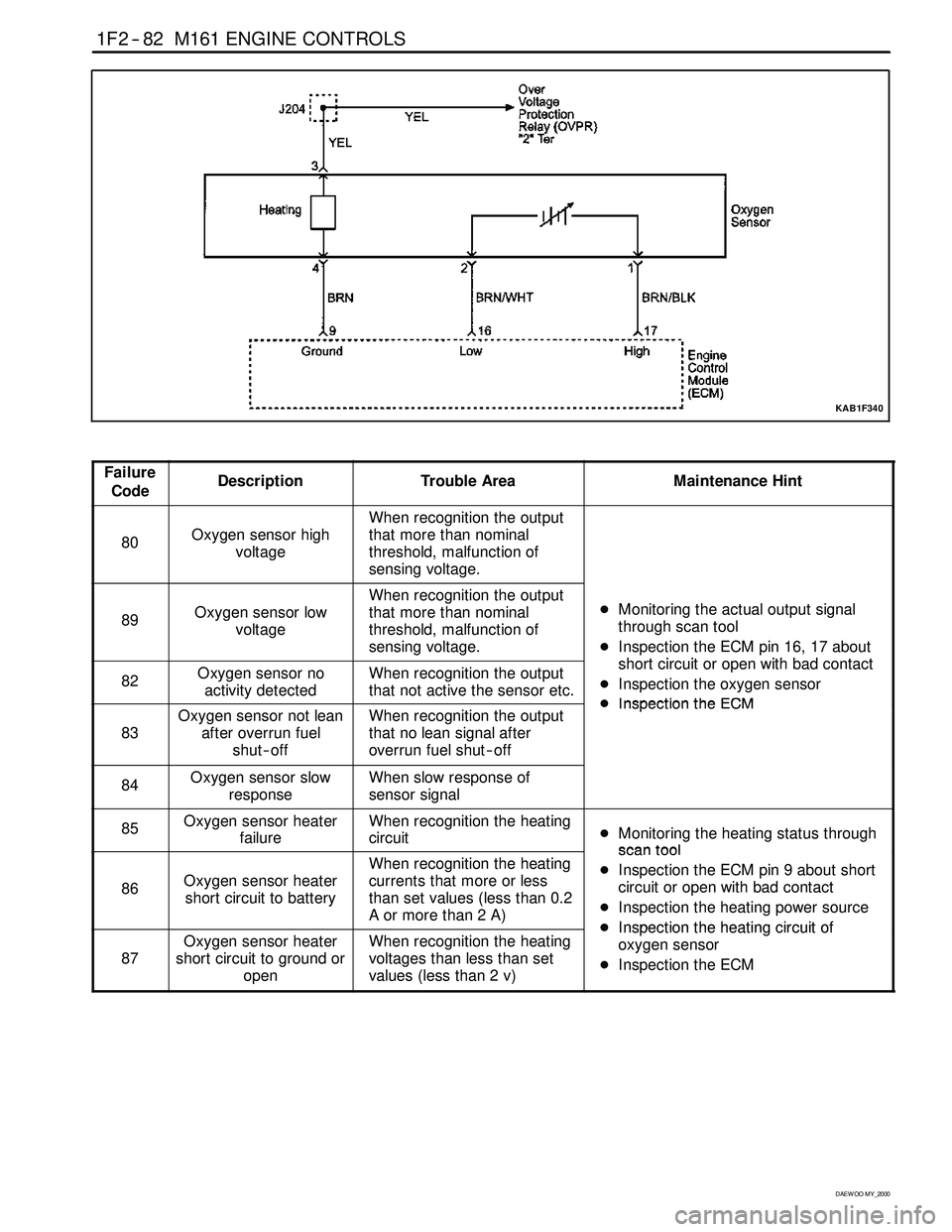
1F2 -- 82 M161 ENGINE CONTROLS
D AEW OO M Y_2000
KAB1F340
Failure
CodeDescriptionTrouble AreaMaintenance Hint
80Oxygen sensor high
voltage
When recognition the output
that more than nominal
threshold, malfunction of
sensing voltage.
89Oxygen sensor low
voltage
When recognition the output
that more than nominal
threshold, malfunction of
sensing voltage.DMonitoring the actual output signal
through scan tool
DInspection the ECM pin 16, 17 about
htiitithbdtt
82Oxygen sensor no
activity detectedWhen recognition the output
that not active the sensor etc.short circuit or open with bad contact
DInspection the oxygen sensor
DInspectiontheECM
83
Oxygen sensor not lean
after overrun fuel
shut -- offWhen recognition the output
that no lean signal after
overrun fuel shut -- offDInspectiontheECM
84Oxygen sensor slow
responseWhen slow response of
sensor signal
85Oxygen sensor heater
failureWhen recognition the heating
circuitDMonitoring the heating status through
scantool
86Oxygen sensor heater
short circuit to battery
When recognition the heating
currents that more or less
than set values (less than 0.2
Aormorethan2A)scantool
DInspection the ECM pin 9 about short
circuit or open with bad contact
DInspection the heating power source
DInspectiontheheatingcircuitof
87
Oxygen sensor heater
short circuit to ground or
openWhen recognition the heating
voltages than less than set
values (less than 2 v)DInspectiontheheating circuitof
oxygen sensor
DInspection the ECM
Page 502 of 2053
1F2 -- 84 M161 ENGINE CONTROLS
D AEW OO M Y_2000
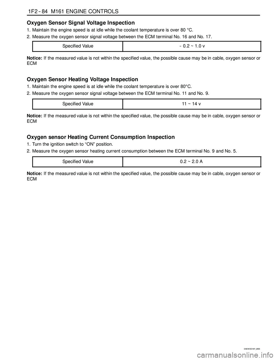
Oxygen Sensor Signal Voltage Inspection
1. Maintain the engine speed is at idle while the coolant temperature is over 80°C.
2. Measure the oxygen sensor signal voltage between the ECM terminal No. 16 and No. 17.
Specified Value
-- 0.2 ~ 1.0 v
Notice:If the measured value is not within the specified value, the possible cause may be in cable, oxygen sensor or
ECM
Oxygen Sensor Heating Voltage Inspection
1. Maintain the engine speed is at idle while the coolant temperature is over 80°C.
2. Measure the oxygen sensor signal voltage between the ECM terminal No. 11 and No. 9.
Specified Value
11 ~ 14 v
Notice:If the measured value is not within the specified value, the possible cause may be in cable, oxygen sensor or
ECM
Oxygen sensor Heating Current Consumption Inspection
1. Turn the ignition switch to “ON” position.
2. Measure the oxygen sensor heating current consumption between the ECM terminal No. 9 and No. 5.
Specified Value
0.2~2.0A
Notice:If the measured value is not within the specified value, the possible cause may be in cable, oxygen sensor or
ECM
Page 565 of 2053

1B3 -- 16 OM600 ENGINE MECHANICAL
D AEW OO M Y_2000
16. Remove the power steering pump lines.
Notice
Completely drain the fluid.
17. Disconnect the fuel feed line with prefilter from the
feed pump on injection pump.
18. Vehicle with automatic transmission.
Remove the hydraulic lines (19, 20) from oil cooler
(2).
19. Disconnect the engine harness.
20. Disconnect the preheating time relay cable.
Page 567 of 2053

1B3 -- 18 OM600 ENGINE MECHANICAL
D AEW OO M Y_2000
27. Disconnect the preheating time relay sensor plug.
28. Disconnect the coolant temperature sensor plug.
29. Disconnect the accelerator cable from the control
linkage.
Installation Notice
Tightening Torque8--18 N∙m (6 -- 13 lb-ft)
30. Loosen the connection of control pressure cable (an
arrow) used in auto transmisson.
Page 648 of 2053

OM600 ENGINE MECHANICAL 1B3 -- 99
D AEW OO M Y_2000
Replacement Procedure
1. Drill a hole into the ring gear (1) (arrow) and snap
with a chisel.
2. Thoroughly clean the collar surfaces of ring gear.
3. Measure diameter (a) of centering collar.
Diameter ’a’275 + 0.5mm
Notice
If out of standard, replace the flywheel.
4. Heat up the new ring gear up to 220_C by using a
heating device.
Notice
Use temperature measuring chalk.
5. Install the new ring gear (1) onto the flywheel by us-
ingadrift.
Page 897 of 2053

REAR AXLE 3D-3
SSANGYONG MY2002
DIAGNOSTIC INFORMATION AND PROCEDURES
Lack of Oil
Low Viscosity of Oil
Inferior Oil
Excessive Backlash of Ring Gears
Worn or Damaged Tooth of Ring and Pinion Gear
Worn or Damaged Tooth of Drive Pinion Gear
Wear of Side Bearing and Side Gear Spline
Bending of Axle Housing
Distortion of Differential Case
Wear of Pinion Shaft
Incorrect Drive Pinion Preload.
Incorrect Contact of Ring Gear and Pinion
Excessive Oil
Fault Seal of Carrier Contact Surface
Axle Housing Crack
Worn or Damaged Oil Seal
Worn or Damaged Tooth of Pinion or Side Gear
Wear of Pinion Shaft
Excessive Backlash of Pinion Gear and Side Gear
Excessive End-Play of Rear Axle Shaft
Incorrect Contact of Side Gear and Differential Case
Axle Housing Crack
Distortion or Poor Installation of Drive pinion Oil Seal
Damaged of Torn Drive Pinion Oil Seal
Loosened Bearing Collar
Worn or Damaged Universal Joint
Worn or damaged Axle Shaft Bearing
Lock of Oil
Insufficient Backlash of Gears
Excessive Preload of BearingReplenish
Replace
Replace
Adjust
Replace
Replace
Replace
Replace
Replace
Replace
Adjust
Reassembly
Adjust
Correct
Replace
Replace
Replace
Replace
Replace
Adjust
Replace
Replace
Replace
Replace
Replace
Replace
Replace
Replenish
Adjust
Adjust Checks Phenomena
Noise
(During Straight
Driving)
Oil Leakage
Noise (During Turning)
Heating
Action
Page 1502 of 2053

SECTION 7A
HEATING AND VENTILATION SYSTEM
CAUTION: The cooling system is pressurized when hot. Injury can result from removing the coolant reservoir
cap before the engine is sufficiently cool.
TABLE OF CONTENTS
Description and Operation ................................7A-2
Heating and Ventilation System .........................7A-2
Components Locator ..........................................7A-3
Heater System ...................................................7A-3
Diagnostic Information and Procedures ..........7A-4
Heater System ...................................................7A-4
Blower Electrical ................................................7A-8
Mode Controls Do Not Work .............................7A-10
Air Source Selection Not Controlled ..................7A-12
Temperature Controls Do Not Work ..................7A-13
Too Much Heat .................................................7A-14
Blower Noise ....................................................7A-16
Repair Instructions ............................................7A-18
On-Vehicle Service..............................................7A-18
Temperature Control Cable Adjustment ............7A-18
Controller Assembly and Temperature
Control Cable .................................................7A-18
Control Assembly Knob Lighting ......................7A-19Air Intake Door Actuator ...................................7A-19
Mode Control Door Actuator .............................7A-20
Heater/Air Distributor Case Assembly ..............7A-20
Blower Motor ....................................................7A-21
Blower Resistor ................................................7A-22
Blower Unit .......................................................7A-22
Heater Inlet Hose ..............................................7A-23
Heater Outlet Hose ...........................................7A-23
Heater Core......................................................7A-24
Rear Heater Duct ..............................................7A-24
Air Filter ............................................................7A-24
Specifications .................................................... 7A-25
Heater Temperature Specification .....................7A-25
Heater Unit .......................................................7A-25
Fastener Tightening Specification .....................7A-25
Schematic and Routing Diagrams ................... 7A-26
Non - A/C Wiring Diagram ................................7A-26
Airflow Through Vents .......................................7A-28
Page 1503 of 2053

SSANGYONG MY2002
7A-2 HEATING AND VENTILATION SYSTEM
DESCRIPTION AND OPERATION
HEATING AND VENTILATION
SYSTEM
The base heater system is designed to provide heating,
ventilation, windshield defrosting, side wind defogging
and rear seat area.
The heater and fan assembly blower regulates the air-
flow from the air inlet for further processing and distribu-
tion.
The heater core transfers the heater from the engine
coolant to the inlet air.
The temperature door regulates the amount of the air
that passes through the heater core. The temperature
door also controls the temperature of the air by control-
ling mix of heated air with the ambient air.
The mode door regulates the flow and distribution of
the processed air to the heater ducts and to the defroster
ducts.
The console mounted heating and ventilation control
panel contains one rotary control knob, one sliding con-
trol lever and six push control knobs, which operate as
follows:
Sliding Temperature Control Lever
•Actuates by cable.
Raise the temperature of the air entering the vehicle
by sliding to the right, or the red portion of the knob.
Five Mode Control Knob
Actuates by electricity.
Regulates the air distribution between the
windshield, the instrument panel, and the floor
vents.
Rotary Blower Control Knob
Turns on to operate the blower motor at four speeds.
Turns OFF to stop the blower.
Operates completely independently from both the
mode control knob and temperature control knob.
Changes the fan speed in any mode and at any
speed.
Intake Air Control Knob
Operates by electricity.
Switches between recirculating the passenger
compartment air and bringing outside air into the
passenger compartment.
Is normally in fresh air mode.
Illuminates the indicator lamp when in the recalculat
ing mode.
Heater Core
The heater core heats the air before enters the vehicle.
Engine coolant is circulated through the core to heat
the outside air passing over the fins of the core. The
core is functional at all times and may be used to
temper conditioned air in the A/C mode as well as in
the heat or the vent mode.