heating SSANGYONG KORANDO 1997 Service Service Manual
[x] Cancel search | Manufacturer: SSANGYONG, Model Year: 1997, Model line: KORANDO, Model: SSANGYONG KORANDO 1997Pages: 2053, PDF Size: 88.33 MB
Page 1524 of 2053

HEATING AND VENTILATION SYSTEM 7A-23
SSANGYONG MY2002
HEATER INLET HOSE
Removal and Installation Procedures
1. Partially drain the cooling system. Refer to Section
1D, Engine Cooling.
2. Remove the clip and slide rearward the inlet heater
hose clamp at the firewall.
3. Gently twist the hose from the left to right and
back again to loosen the bond between the hose
and the tube.
4. Remove the end of the hose from the tube.
KAA7A150
KAA7A160
KAA7A170
KAA7A180
5. Remove the clip and slide rearward the inlet heater
hose at the engine block.
6. Remove the inlet heater hose from the vehicle.
7. Installation should follow the removal procedure
in the reverse order.
HEATER OUTLET HOSE
Removal and Installation Procedures
1. Partially drain the cooling system. Refer to Section
1D, Engine Cooling.
2. Remove the clip and slide rearward the outlet
heater hose clamp at the firewall.
3. Gently twist the hose from the left to right and
back again to loosen the bond between the hose
and the tube.
4. Remove the end of the hose from the tube.
5. Remove the intake manifolds. Refer to Section 1C,
DOHC Engine Mechanical.
6. Remove the clip and slide rearward the outlet
heater hose at the thermostat housing.
7. Remove the outlet heater hose from the vehicle.
8. Installation should follow the removal procedure
in the reverse order.
Page 1525 of 2053

SSANGYONG MY2002
7A-24 HEATING AND VENTILATION SYSTEM
HEATER CORE
Removal and Installation Procedures
1. Disconnect the negative battery cable.
2. Remove the heater/air distribution case from the
vehicle. Refer to “Heater/Air Distribution Case
Assembly” in this section.
3. Remove the plastic holder and two screws that
secure the heater core to heater/air distributor case
assembly.
4. Slowly separate the heater/air distributor case as-
sembly and remove the heater core.
5. Installation should follow the removal procedure
in the reverse order.
REAR HEATER DUCT
This vehicle is equipped with rear seat heater ducts.
Should there be no airflow to the rear, look for any ob-
structions, such as items on the floor under the front
seats. Also check for air leaks between the heater/air
distributor assembly and the rear ducts.
KAA7A190
KAA7D130
KAA7D140
AIR FILTER
Removal and Installation Procedures
Notice: Replace earlier if air pollution is heavy.
1. Open the glove box and pull it inward to release
the upper left and right locking portion.
Notice: Remove the glove box by unscrewing
lower 2 screws, if necessary.
2. Press the 2 filter cover holds and remove the air
filter cover.
3. Remove the 2 air filters.
Notice: For installation, remember the installed
direction of the air filter before removal.
Replacement Interval Every 10,000 km
Page 1526 of 2053
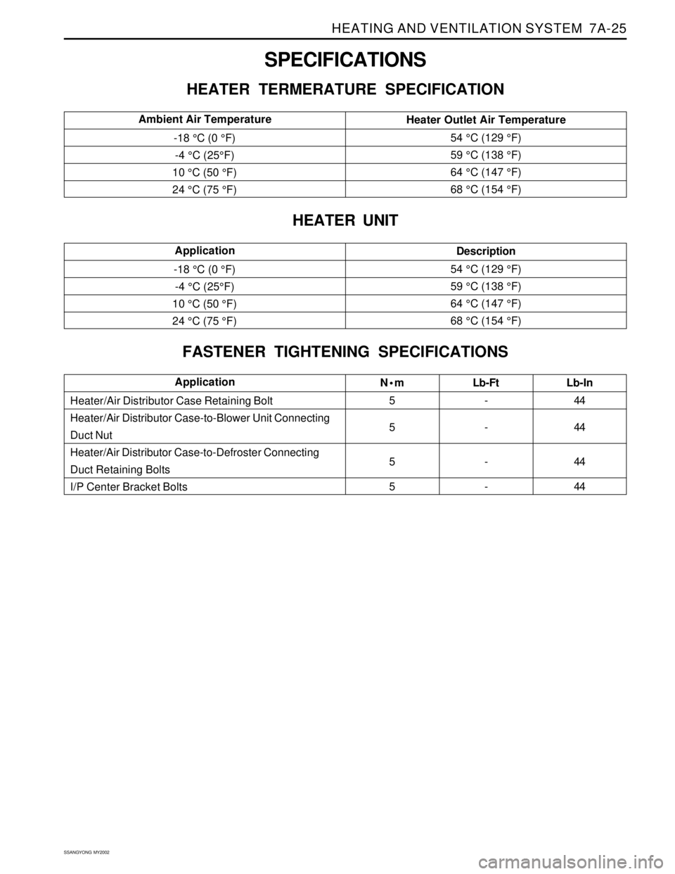
HEATING AND VENTILATION SYSTEM 7A-25
SSANGYONG MY2002
SPECIFICATIONS
HEATER TERMERATURE SPECIFICATION
Nm
5
5
5
5Lb-Ft
-
-
-
- Heater/Air Distributor Case Retaining Bolt
Heater/Air Distributor Case-to-Blower Unit Connecting
Duct Nut
Heater/Air Distributor Case-to-Defroster Connecting
Duct Retaining Bolts
I/P Center Bracket BoltsLb-In
44
44
44
44Application
Heater Outlet Air Temperature
54 °C (129 °F)
59 °C (138 °F)
64 °C (147 °F)
68 °C (154 °F) -18 °C (0 °F)
-4 °C (25°F)
10 °C (50 °F)
24 °C (75 °F)Ambient Air Temperature
FASTENER TIGHTENING SPECIFICATIONS
HEATER UNIT
Description
54 °C (129 °F)
59 °C (138 °F)
64 °C (147 °F)
68 °C (154 °F) -18 °C (0 °F)
-4 °C (25°F)
10 °C (50 °F)
24 °C (75 °F)Application
Page 1527 of 2053

SSANGYONG MY2002
7A-26 HEATING AND VENTILATION SYSTEM
NON-A/C WIRING DIAGRAMS (1 OF 2)
SCHEMATIC AND ROUTING DIAGRAMS
KAA7A200
Page 1528 of 2053

HEATING AND VENTILATION SYSTEM 7A-27
SSANGYONG MY2002
NON-A/C WIRING DIAGRAMS (2 OF 2)
KAA7A210
Page 1529 of 2053

SSANGYONG MY2002
7A-28 HEATING AND VENTILATION SYSTEM
AIRFLOW THROUGH VENTS
KAA7A220
1 Side Ventilation Vents (Face Position)
2 Front windshiel Defroster Vents
3 Conter Ventilation Vents (Face Position)4 Ventilation Vents (Face Position)
5 Side Door Window Defroster Vents
6 Rear Ventilation Vents
Page 1530 of 2053

SECTION 7C
MANUAL CONTROL / SEMIAUTO
TEMPERATURE CONTROL HEATING,
VENTILATION AND AIR CONDITIONING
SYSTEM
CAUTION: Disconnect the negative battery cable before removing or installing any electrical unit or when
a tool or equipment could easily come in contact with exposed electrical terminals. Disconnecting this
cable will help prevent personal injury and damage to the vehicle. The ignition must also be in LOCK
unless other-wise noted.
TABLE OF CONTENTS
Specifications.......................................................7C-2
Refrigerant..........................................................7C-2
Evaporator Unit....................................................7C-2
Blower Unit..........................................................7C-2
Compressor.........................................................7C-2
Condenser...........................................................7C-2
Receiver Drier......................................................7C-2
Pressure Switch...................................................7C-3
Air Filter...............................................................7C-3
Heater Unit..........................................................7C-3
Fastener Tightening Specifications.......................7C-3
Diagnosis..............................................................7C-4
Defectives in Fan Motor Circuit.............................7C-5
Defectives in Compressor Circuit.........................7C-6
Diagnosis Using the Manifold Gauge...................7C-7Component Locator.............................................7C-9
Ventilation............................................................7C-9
Heater System ................................................... 7C-11
Air Conditioner System...................................... 7C-12
Diesel Engine .................................................... 7C-12
Gasoline Engine................................................ 7C-13
Maintenance and Repair................................... 7C-14
Refrigerant Charging .......................................... 7C-14
Compressor Oil Replacement............................ 7C-18
Repair Instructions.............................................. 7C-19
On-Vehicle Service............................................... 7C-19
Condener.......................................................... 7C-19
Receiver Drier.................................................... 7C-21
Air - Conditioner Compressor............................. 7C-23
Heater and Air Conditioner Control Box.............. 7C-24
Air Filter............................................................. 7C-25
Page 1532 of 2053

MANUAL & SEMIAUTO-HVAC 7C-3
SSANGYONG MY2002
PRESSURE SWITCH
Type
High (OFF)
Low (ON)ApplicationDescriptionDirect
OFF : 32 ± 2 Kgf/cm
2, DIFF : 6 ± 2 Kgf/cm2
OFF : 2.0 ± 0.2 Kgf/cm2, ON : 2.1 ± 0.2 Kgf/cm2
AIR FILTER
ReplacementApplicationDescriptionEvery 12,000 km (replace earlier if air pollution is heavy)
HEATER UNIT
Heater Core Type
Heating Capacity
Heater Core Size (L x W x T)ApplicationDescription2-ROW
4,600 Kcal/h (AT 300 CMH)
219.5 x 151.8 x 52
FASTENER TIGHTENING SPECIFICATIONS
N•m
4 - 6
4 - 6
4 - 6
5 - 8
4 - 6
20 - 30
20 - 26Lb-Ft
2.9 - 4.4
2.9 - 4.4
2.9 - 4.4
3.7 - 5.9
2.9 - 4.4
14.7 - 22.1
14.7 - 19.1 Condenser Bolt
Condenser Fan Nut
Condenser Bolt
Receiver Drier Pipe Bolt
Receiver Drier Pipe Bolt (Condenser)
Pressure Pipe Bolt
Pressure Mounting BoltLb-In
35.4 - 53.1
35.4 - 53.1
35.4 - 53.1
44.2 - 70.8
35.4 - 53.1
177.0 - 265.5
177.0 - 230.1Application
Page 1545 of 2053

SSANGYONG MY2002
7C-16 MANUAL & SEMIAUTO-HVAC
Charging Refrigerant
Charging for Gas
1. Connect the tap valve to the refrigerant tank.
2. Open the low pressure and adjust the low-side
reading below 4.2 kg/cm
2.
3. Place the refrigerant tank in the warm water
(40 °C) and keep the gas pressure in the refrigerant
tank higher than the gas pressure in the charging
valve.
4. Run the engine at high speed and operate A/C
system.
Notice: Place the refrigerant tank on the flat floor
to protect the liquid refrigerant from coming
through the suction inlet resulting in the
compressor’s damage.
5. Charge the specified amount to the charging valve
and close the low pressure valve.
Notice:
If the charging speed is low, it’s more efficient
to place the refrigerant tank in the warm water
(40 °C). But the temperature should keep below
(52 °C) at any situation.
Be careful not to contact the heating device or
material.
Charging for Liquid
Notice:
Do not operate when charging the system through
the high-side rpessure.
Do not open the low pressure valve when charging
the system by the liquid refrigerant.
1. Tighten both high pressure and low pressure
completely before evacuating the charging valve.
2. Connect the tap valve of the refrigerant tank.
3. Open the high pressure valve and turn the
refrigerant tank upside down.Single: 850 ± 50 g
Dual: 1200 ± 50 g
Specified amount
YAD7B210
YAD7B220
YAD7B230
Page 1555 of 2053

SECTION 7D
FULL AUTOMATIC TEMPERATURE
CONTROL HEATING, VENTILATION AND
AIR CONDITIONING SYSTEM
FATC (Full Automatic Temperature Control) is full automatic heater and airconditioning system that detects
incar temperature, ambient temperature, sun load and coolant temperature and controls airconditioner
system blowing capacity, outlet temperature and intaking/outlet mode to maintain interior comfort.
TABLE OF CONTENTS
Specifications.......................................................7D-2
Refrigerant..........................................................7D-2
Evaporator Unit....................................................7D-2
Blower Unit..........................................................7D-2
Compressor.........................................................7D-2
Condenser...........................................................7D-2
Receiver Drier......................................................7D-2
Pressure Switch...................................................7D-3
Air Filter...............................................................7D-3
Heater Unit..........................................................7D-3
Service Specifications ..........................................7D-4
Fastener Tightening Specifications.......................7D-4Schematic and Routing Diagrams.......................7D-5
Circuit Diagram....................................................7D-5
FATC Block Diagram...........................................7D-6
Component Locator.............................................7D-7
Ventilation System...............................................7D-7
Function Description............................................7D-8
Diagnosis..............................................................7D-9
Diagnosis Test.....................................................7D-9
Maintenance and Repair................................... 7D-13
FATC Control Panel............................................ 7D-13
Air Filter............................................................. 7D-16
Troubleshooting................................................. 7D-17