stop start SSANGYONG KORANDO 1997 Service User Guide
[x] Cancel search | Manufacturer: SSANGYONG, Model Year: 1997, Model line: KORANDO, Model: SSANGYONG KORANDO 1997Pages: 2053, PDF Size: 88.33 MB
Page 947 of 2053
SSANGYONG MY2002
4C-4 POWER BOOSTER
DIAGNOSTIC INFORMATION AND PROCEDURES
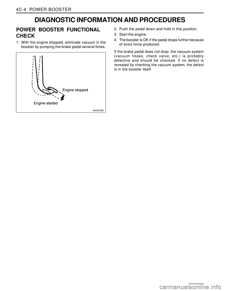
KAA4C020
2. Push the pedal down and hold in this position.
3. Start the engine.
4. The booster is OK if the pedal drops further because
of extra force produced.
If the brake pedal does not drop, the vacuum system
(vacuum hoses, check valve, etc.) is probably
defective and should be checked. If no defect is
revealed by checking the vacuum system, the defect
is in the booster itself.POWER BOOSTER FUNCTIONAL
CHECK
1. With the engine stopped, eliminate vacuum in the
booster by pumping the brake pedal several times.
Page 998 of 2053
ABS AND TCS 4F-15
SSANGYONG MY2002
DIAGNOSIS
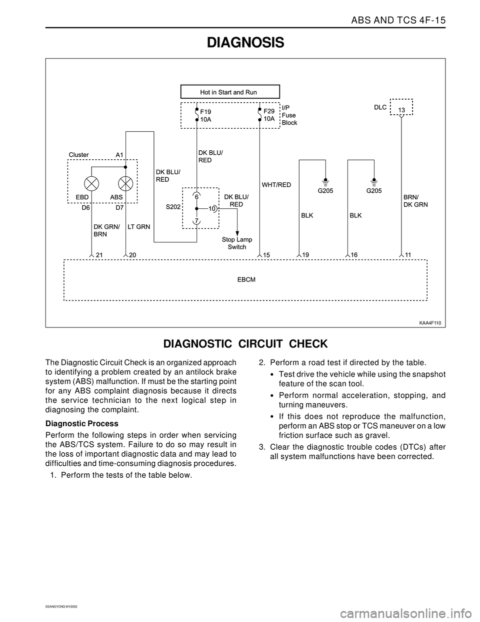
KAA4F110
DIAGNOSTIC CIRCUIT CHECK
The Diagnostic Circuit Check is an organized approach
to identifying a problem created by an antilock brake
system (ABS) malfunction. If must be the starting point
for any ABS complaint diagnosis because it directs
the service technician to the next logical step in
diagnosing the complaint.
Diagnostic Process
Perform the following steps in order when servicing
the ABS/TCS system. Failure to do so may result in
the loss of important diagnostic data and may lead to
difficulties and time-consuming diagnosis procedures.
1. Perform the tests of the table below.2. Perform a road test if directed by the table.
Test drive the vehicle while using the snapshot
feature of the scan tool.
Perform normal acceleration, stopping, and
turning maneuvers.
If this does not reproduce the malfunction,
perform an ABS stop or TCS maneuver on a low
friction surface such as gravel.
3. Clear the diagnostic trouble codes (DTCs) after
all system malfunctions have been corrected.
Page 1096 of 2053
5A-2 AUTOMATIC TRANSMISSION
SSANGYONG MY2002
OPERATORS INTERFACES
There are three operator interfaces as the following;
•Gear Shift Control Lever
Driving Mode Selector
Indicator Light
Gear Shift Control lever
The transmission uses a conventional shift control lever.
The gear shift control lever can be moved from one
position to another within the staggered configuration
of the shift control lever gate to positively indicate the
gear selection.
DESCRIPTION AND OPERATION
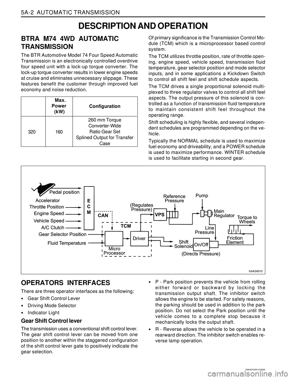
BTRA M74 4WD AUTOMATIC
TRANSMISSION
The BTR Automotive Model 74 Four Speed Automatic
Transmission is an electronically controlled overdrive
four speed unit with a lock-up torque converter. The
lock-up torque converter results in lower engine speeds
at cruise and eliminates unnecessary slippage. These
features benefit the customer through improved fuel
economy and noise reduction.Of primary significance is the Transmission Control Mo-
dule (TCM) which is a microprocessor based control
system.
The TCM utilizes throttle position, rate of throttle open-
ing, engine speed, vehicle speed, transmission fluid
temperature, gear selector position and mode selector
inputs, and in some applications a Kickdown Switch
to control all shift feel and shift schedule aspects.
The TCM drives a single proportional solenoid multi-
plexed to three regulator valves to control all shift feel
aspects. The output pressure of this solenoid is con-
trolled as a function of transmission fluid temperature
to maintain consistent shift feel throughout the
operating range.
Shift scheduling is highly flexible, and several indepen-
dent schedules are programmed depending on the ve-
hicle.
Typically the NORMAL schedule is used to maximize
fuel economy and driveability, and a POWER schedule
is used to maximize performance. WINTER schedule
is used to facilitate starting in second gear. Configuration Max.
Power
(kW)
320 160260 mm Torque
Converter-Wide
Ratio Gear Set
Splined Output for Transfer
Case
P - Park position prevents the vehicle from rolling
either forward or backward by locking the
transmission output shaft. The inhibitor switch
allows the engine to be started. For safety reasons,
the parking should be used in addition to the park
position. Do not select the Park position until the
vehicle comes to a complete stop because it
mechanically locks the output shaft.
R - Reverse allows the vehicle to be operated in a
rearward direction. The inhibitor switch enables re-
verse lamp operation.
KAA5A010
Page 1133 of 2053
AUTOMATIC TRANSMISSION 5A-39
SSANGYONG MY2002
4. Place a fluid container below the fluid filler plug.
5. Clean all dirt from around the fluid filler plug.
Remove the fluid filler plug. Clean the filler plug
and check that there is no damage to the ‘O’ ring.
If fluid drains through the filler hole the transmis-
sion may have been overfilled. When the fluid
stops draining the fluid level is correct. Install
the fluid filler plug and tighten it to 33 Nm (24
lb-ft).
If fluid does not drain through the filler hole, the
transmission fluid level may be low. Install the
filler pump into the filler hole. Lower the vehicle
with the filler pump still connected and partially
fill the fluid through the filler hole.
Start the vehicle in P (Park) with the parking
brake and the brake applied. With the engine
idling, move the gear shift. control lever through
the gear ranges, pausing a few seconds in each
range and adding the fluid until gear application
is felt.
Return the gear shift lever to P (Park).
Turn the engine OFF and raise the vehicle. When
the three minutes passed after the engine
stopped, remove the filler pump.
Check if the fluid level is aligned with the bottom
of the filler hole. If not, add a small quantity of
fluid to the correct level. Install the fluid filler
plug and tighten it to 33 Nm (24 lb-ft).
If fluid does not drain through the filler hole al-
though adding a total of 1.5 liters, the transmission
should be inspected for fluid leaks and any leaks
should be fixed before setting the transmission
fluid level.
6. When the fluid level checking procedure is com-
pleted, wipe any fluid around the filler plug with a
rag or shop towel.
Fluid Level Set After Service
1. Depending on the service procedure performed,
add the following amounts of fluid through the filler
plug hole prior to adjusting the fluid level:
Converter empty 8.0 liters (8.5 quarts)
Converter full 3.8 liters (4.0 quarts)
2. Follow steps 1 through 4 of the Fluid Level Diagnosis
Procedure.
3. Clean all dirt from around the fluid filler plug.
Remove the fluid filler plug. Clean the filler plug
and check that there is no damage to the ‘O’ ring.
4. Lower the vehicle with the filler pump still connected
and start the vehicle in P (Park) with the parking
brake and the brake applied. With the engine idling,
move the gear shift control lever through the gear
ranges, pausing a few seconds in each range and
adding the fluid until gear application is felt.Then add an additional 0.5 litres of fluid. Return
the gear shift lever to P (Park). Turn the engine OFF
and raise the vehicle. Install the fluid filler plug and
tighten it to 33 Nm (24 lb-ft).
5. Drive the vehicle at 3.5 to 4.5 kilometers with light
throttle so that the engine does not exceed 2500
rpm.
This should result in the transmission temperature
being in the range 50 - 60 °C (82 - 140 °F). With the
brake applied, move the shift lever through the gear
ranges, pausing a few seconds in each range at
the engine idling.
6. Return the gear shift lever to P (Park).
Turn the en-gine OFF and raise the vehicle on the
hoist, if applicable, ensuring the vehicle is level.
When the three minutes passed after the engine
stopped, remove the filler plug.
Check if the fluid level is aligned with the bottom of
the filler hole. If not, add a small quantity of fluid to
the correct level. Install the fluid filler plug and
tighten it to 33 Nm (24 lb-ft).
7. Wipe any fluid around the filler plug with a rag or
shop towel.
FLUID LEAK DIAGNOSIS AND
REPAIR
The cause of most external leaks can generally be lo-
cated and repaired with the transmission in the vehicle.
Methods for Locating Leaks
General Method
1. Verify that the leak is transmission fluid.
2. Thoroughly clean the suspected leak area.
3. Drive the vehicle for approximately 25 km (15 miles)
or until the transmission reaches normal operating
temperature (88 °C, 190 °F).
4. Park the vehicle over clean paper or cardboard.
5. Turn the engine OFF and look for fluid spots on the
paper.
6. Make the necessary repairs to correct the leak.
Powder Method
1. Thoroughly clean the suspected leak area.
2. Apply an aerosol type powder (foot powder) to the
suspected leak area.
3. Drive the vehicle for approximately 25 km (15 miles)
or until the transmission reaches normal operating
temperature (88 °C, 190 °F).
4. Turn the engine OFF.
5. Inspect the suspected leak area and trace the leak
path through the powder to find the source of the
leak.
6. Make the necessary repairs.
Page 1375 of 2053
TRANSFER CASE 5D1-5
SSANGYONG MY2002
The motor reaches its destination.
The motor is on for 5 seconds without reaching its
destination. The shift has failed and the TCCU will
respond as default mode.
A fault occurs with either the motor or position
encoder. Refer to the diagnosis requirement.
When the motor is energized, the Ignition, 4H/4L
switch, propeller shaft speeds, and transmission
neutral inputs are ignored.
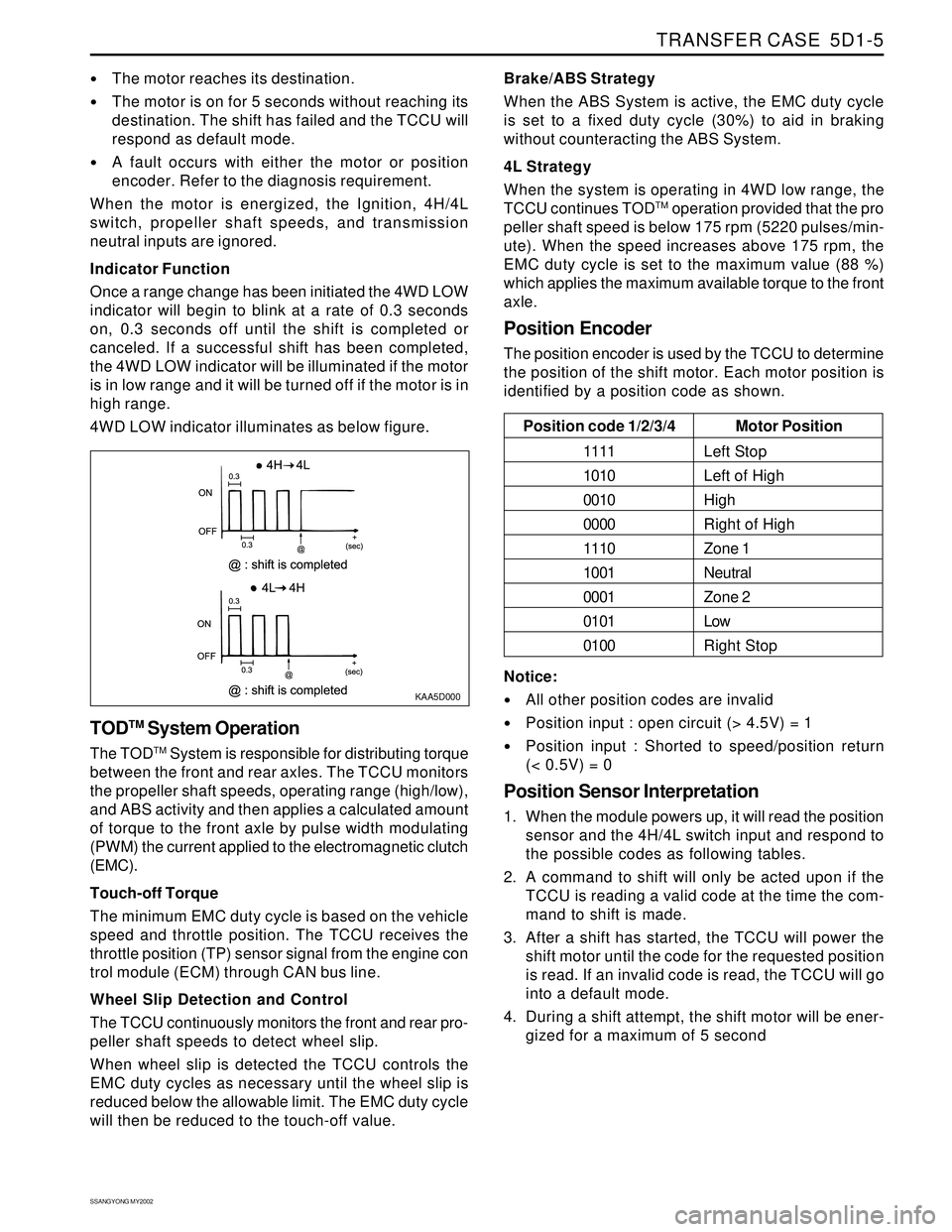
Indicator Function
Once a range change has been initiated the 4WD LOW
indicator will begin to blink at a rate of 0.3 seconds
on, 0.3 seconds off until the shift is completed or
canceled. If a successful shift has been completed,
the 4WD LOW indicator will be illuminated if the motor
is in low range and it will be turned off if the motor is in
high range.
4WD LOW indicator illuminates as below figure.
KAA5D000
TODTM System Operation
The TODTM System is responsible for distributing torque
between the front and rear axles. The TCCU monitors
the propeller shaft speeds, operating range (high/low),
and ABS activity and then applies a calculated amount
of torque to the front axle by pulse width modulating
(PWM) the current applied to the electromagnetic clutch
(EMC).
Touch-off Torque
The minimum EMC duty cycle is based on the vehicle
speed and throttle position. The TCCU receives the
throttle position (TP) sensor signal from the engine con
trol module (ECM) through CAN bus line.
Wheel Slip Detection and Control
The TCCU continuously monitors the front and rear pro-
peller shaft speeds to detect wheel slip.
When wheel slip is detected the TCCU controls the
EMC duty cycles as necessary until the wheel slip is
reduced below the allowable limit. The EMC duty cycle
will then be reduced to the touch-off value.Brake/ABS Strategy
When the ABS System is active, the EMC duty cycle
is set to a fixed duty cycle (30%) to aid in braking
without counteracting the ABS System.
4L Strategy
When the system is operating in 4WD low range, the
TCCU continues TOD
TM operation provided that the pro
peller shaft speed is below 175 rpm (5220 pulses/min-
ute). When the speed increases above 175 rpm, the
EMC duty cycle is set to the maximum value (88 %)
which applies the maximum available torque to the front
axle.
Position Encoder
The position encoder is used by the TCCU to determine
the position of the shift motor. Each motor position is
identified by a position code as shown.
Motor Position
Left Stop
Left of High
High
Right of High
Zone 1
Neutral
Zone 2
Low
Right Stop Position code 1/2/3/4
1111
1010
0010
0000
1110
1001
0001
0101
0100
Notice:
All other position codes are invalid
Position input : open circuit (> 4.5V) = 1
Position input : Shorted to speed/position return
(< 0.5V) = 0
Position Sensor Interpretation
1. When the module powers up, it will read the position
sensor and the 4H/4L switch input and respond to
the possible codes as following tables.
2. A command to shift will only be acted upon if the
TCCU is reading a valid code at the time the com-
mand to shift is made.
3. After a shift has started, the TCCU will power the
shift motor until the code for the requested position
is read. If an invalid code is read, the TCCU will go
into a default mode.
4. During a shift attempt, the shift motor will be ener-
gized for a maximum of 5 second
Page 1402 of 2053
SSANGYONG MY2002
5D2-2 TRANSFER CASE (PART TIME - 4408)
2WD Drive (Rear
Wheel Drive)
4WD Drive (High
Speed)
4WD Drive (Low
Speed)
2WD Drive
↔ 4WD
Drive (High Speed)
2WD Drive, 4WD
Drive (High Speed)
↔ 4WD Drive (Low
Speed)
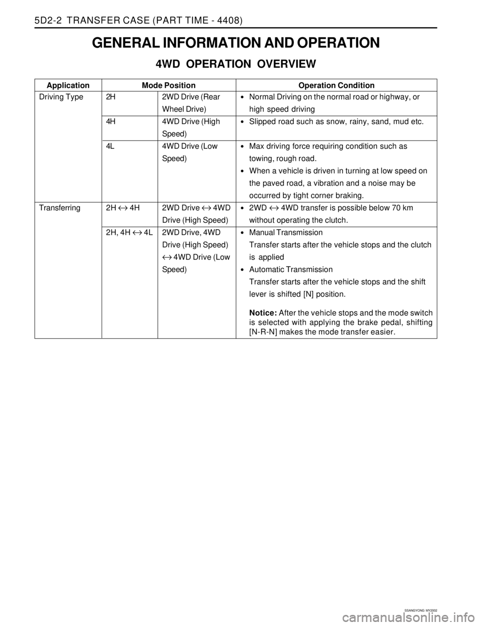
GENERAL INFORMATION AND OPERATION
4WD OPERATION OVERVIEW
Driving Type
Transferring2H
4H
4L
2H
↔ 4H
2H, 4H
↔ 4L Application
•Normal Driving on the normal road or highway, or
high speed driving
Slipped road such as snow, rainy, sand, mud etc.
Max driving force requiring condition such as
towing, rough road.
When a vehicle is driven in turning at low speed on
the paved road, a vibration and a noise may be
occurred by tight corner braking.
2WD ↔ 4WD transfer is possible below 70 km
without operating the clutch.
Manual Transmission
Transfer starts after the vehicle stops and the clutch
is applied
Automatic Transmission
Transfer starts after the vehicle stops and the shift
lever is shifted [N] position.
Notice: After the vehicle stops and the mode switch
is selected with applying the brake pedal, shifting
[N-R-N] makes the mode transfer easier.
Operation ConditionMode Position
Page 1446 of 2053
SSANGYONG MY2002
6A-4 POWER STEERING SYSTEM
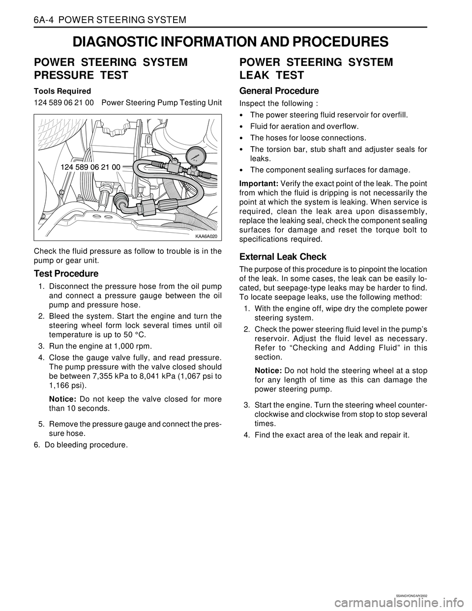
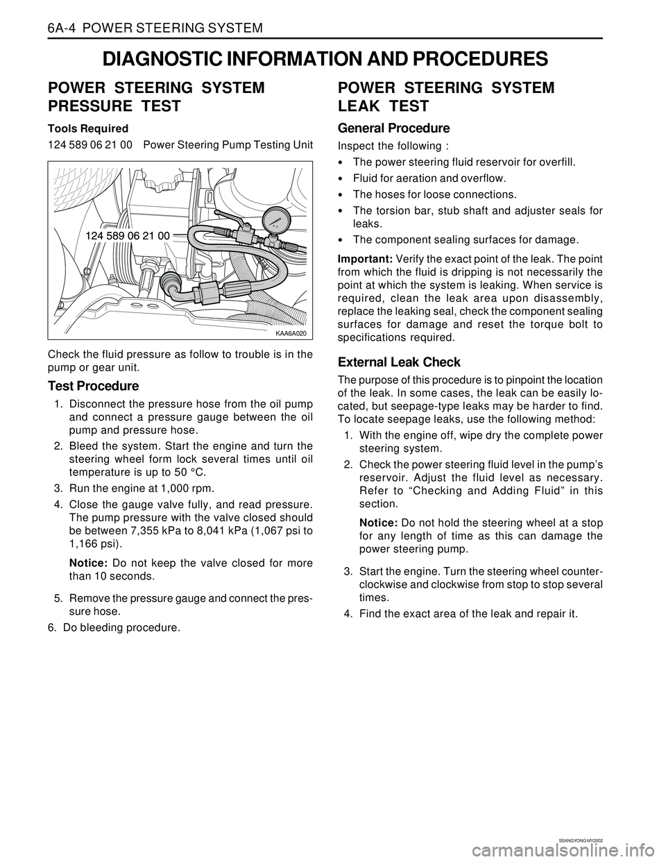
KAA6A020
DIAGNOSTIC INFORMATION AND PROCEDURES
POWER STEERING SYSTEM
PRESSURE TEST
Tools Required
124 589 06 21 00 Power Steering Pump Testing Unit
Check the fluid pressure as follow to trouble is in the
pump or gear unit.
Test Procedure
1. Disconnect the pressure hose from the oil pump
and connect a pressure gauge between the oil
pump and pressure hose.
2. Bleed the system. Start the engine and turn the
steering wheel form lock several times until oil
temperature is up to 50 °C.
3. Run the engine at 1,000 rpm.
4. Close the gauge valve fully, and read pressure.
The pump pressure with the valve closed should
be between 7,355 kPa to 8,041 kPa (1,067 psi to
1,166 psi).
Notice: Do not keep the valve closed for more
than 10 seconds.
5. Remove the pressure gauge and connect the pres-
sure hose.
6. Do bleeding procedure.
POWER STEERING SYSTEM
LEAK TEST
General Procedure
Inspect the following :
The power steering fluid reservoir for overfill.
Fluid for aeration and overflow.
The hoses for loose connections.
The torsion bar, stub shaft and adjuster seals for
leaks.
The component sealing surfaces for damage.
Important: Verify the exact point of the leak. The point
from which the fluid is dripping is not necessarily the
point at which the system is leaking. When service is
required, clean the leak area upon disassembly,
replace the leaking seal, check the component sealing
surfaces for damage and reset the torque bolt to
specifications required.
External Leak Check
The purpose of this procedure is to pinpoint the location
of the leak. In some cases, the leak can be easily lo-
cated, but seepage-type leaks may be harder to find.
To locate seepage leaks, use the following method:
1. With the engine off, wipe dry the complete power
steering system.
2. Check the power steering fluid level in the pump’s
reservoir. Adjust the fluid level as necessary.
Refer to “Checking and Adding Fluid” in this
section.
Notice: Do not hold the steering wheel at a stop
for any length of time as this can damage the
power steering pump.
3. Start the engine. Turn the steering wheel counter-
clockwise and clockwise from stop to stop several
times.
4. Find the exact area of the leak and repair it.
Page 1447 of 2053
POWER STEERING SYSTEM 6A-5
SSANGYONG MY2002
BLEEDING THE POWER
STEERING SYSTEM
1. Disconnect the fuel line. Using a starter motor,
crank the engine and turn the steering wheel from
lock to start 5 or 6 times.
Notice: Do bleeding with engine cranking. If bleed
with idling, there can be a air contact with oil.
2. Connect the fuel feed line and start the engine at
idle speed.
3. Turn the steering wheel from lock to lock until there
is no more air in oil reservoir.
4. Connect the oil level is within specification.
5. By turning the steering wheel left to right, check
the oil level change.
Notice: If oil is not changes more than 5 mm, do
bleeding again. If oil level rises suddenly when
stopped engine, again.
MAINTENANCE
CHECKING AND ADDING FLUID
Notice: When adding fluid or making a complete fluid
change, always use DEXRON. - II power steering fluid.
Failure to use the proper fluid will cause hose and seal
damage and fluid leaks.
1. The power steering fluid level is indicated by marks
on a fluid level indicator on the fluid reservoir cap.
2. If the fluid is warmed up to 66 °C (150 °F), the fluid
level should be between the MAX and MIN marks.
Add fluid as needed.
3. If the fluid is cool, 21 °C (70 °F), the fluid level should
be at the MIN mark. Add fluid as needed.
Page 1455 of 2053
SSANGYONG MY2002
6A-4 POWER STEERING SYSTEM
KAA6A020
DIAGNOSTIC INFORMATION AND PROCEDURES
POWER STEERING SYSTEM
PRESSURE TEST
Tools Required
124 589 06 21 00 Power Steering Pump Testing Unit
Check the fluid pressure as follow to trouble is in the
pump or gear unit.
Test Procedure
1. Disconnect the pressure hose from the oil pump
and connect a pressure gauge between the oil
pump and pressure hose.
2. Bleed the system. Start the engine and turn the
steering wheel form lock several times until oil
temperature is up to 50 °C.
3. Run the engine at 1,000 rpm.
4. Close the gauge valve fully, and read pressure.
The pump pressure with the valve closed should
be between 7,355 kPa to 8,041 kPa (1,067 psi to
1,166 psi).
Notice: Do not keep the valve closed for more
than 10 seconds.
5. Remove the pressure gauge and connect the pres-
sure hose.
6. Do bleeding procedure.
POWER STEERING SYSTEM
LEAK TEST
General Procedure
Inspect the following :
The power steering fluid reservoir for overfill.
Fluid for aeration and overflow.
The hoses for loose connections.
The torsion bar, stub shaft and adjuster seals for
leaks.
The component sealing surfaces for damage.
Important: Verify the exact point of the leak. The point
from which the fluid is dripping is not necessarily the
point at which the system is leaking. When service is
required, clean the leak area upon disassembly,
replace the leaking seal, check the component sealing
surfaces for damage and reset the torque bolt to
specifications required.
External Leak Check
The purpose of this procedure is to pinpoint the location
of the leak. In some cases, the leak can be easily lo-
cated, but seepage-type leaks may be harder to find.
To locate seepage leaks, use the following method:
1. With the engine off, wipe dry the complete power
steering system.
2. Check the power steering fluid level in the pump’s
reservoir. Adjust the fluid level as necessary.
Refer to “Checking and Adding Fluid” in this
section.
Notice: Do not hold the steering wheel at a stop
for any length of time as this can damage the
power steering pump.
3. Start the engine. Turn the steering wheel counter-
clockwise and clockwise from stop to stop several
times.
4. Find the exact area of the leak and repair it.
Page 1456 of 2053
POWER STEERING SYSTEM 6A-5
SSANGYONG MY2002
BLEEDING THE POWER
STEERING SYSTEM
1. Disconnect the fuel line. Using a starter motor,
crank the engine and turn the steering wheel from
lock to start 5 or 6 times.
Notice: Do bleeding with engine cranking. If bleed
with idling, there can be a air contact with oil.
2. Connect the fuel feed line and start the engine at
idle speed.
3. Turn the steering wheel from lock to lock until there
is no more air in oil reservoir.
4. Connect the oil level is within specification.
5. By turning the steering wheel left to right, check
the oil level change.
Notice: If oil is not changes more than 5 mm, do
bleeding again. If oil level rises suddenly when
stopped engine, again.
MAINTENANCE
CHECKING AND ADDING FLUID
Notice: When adding fluid or making a complete fluid
change, always use DEXRON. - II power steering fluid.
Failure to use the proper fluid will cause hose and seal
damage and fluid leaks.
1. The power steering fluid level is indicated by marks
on a fluid level indicator on the fluid reservoir cap.
2. If the fluid is warmed up to 66 °C (150 °F), the fluid
level should be between the MAX and MIN marks.
Add fluid as needed.
3. If the fluid is cool, 21 °C (70 °F), the fluid level should
be at the MIN mark. Add fluid as needed.