stop start SSANGYONG KORANDO 1997 Service Repair Manual
[x] Cancel search | Manufacturer: SSANGYONG, Model Year: 1997, Model line: KORANDO, Model: SSANGYONG KORANDO 1997Pages: 2053, PDF Size: 88.33 MB
Page 117 of 2053
M162 ENGINE MECHANICAL 1B1 -- 91
D AEW OO M Y_2000
8. Temporarily tighten the oil filter cover. Install the oil
filter remover 103 589 02 09 00, and then complete-
ly tighten it.
Installation Notice
Tightening Torque
25 NSm (18 lb-ft)
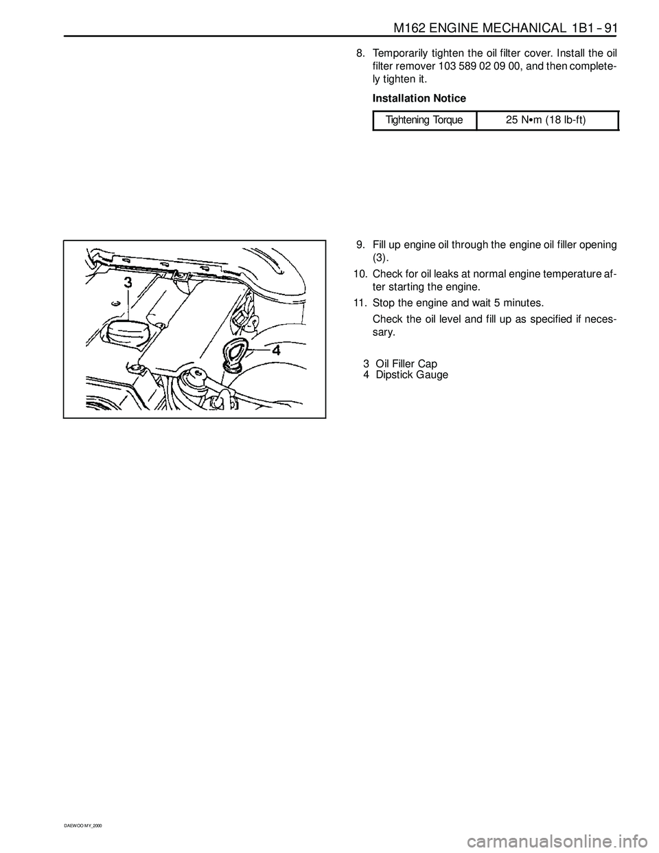
9. Fill up engine oil through the engine oil filler opening
(3).
10. Check for oil leaks at normal engine temperature af-
ter starting the engine.
11. Stop the engine and wait 5 minutes.
Check the oil level and fill up as specified if neces-
sary.
3 Oil Filler Cap
4 Dipstick Gauge
Page 178 of 2053

M162 ENGINE CONTROLS 1F1 -- 15
D AEW OO M Y_2000
FAILURE CODES TABLE (Cont’d)
Failure
codeSee
PageDescription
401F1 -- 51Purge control valve short circuit to battery
411F1 -- 51Purge control valve short circuit to ground or open
441F1 -- 72Cooling fan (HI) relay short circuit to power
451F1 -- 72Cooling fan (HI) relay short circuit to ground or open
541F1 -- 51Purge control circuit malfunction
561F1 -- 33No.1 knock sensor signal failure
571F1 -- 33No.2 knock sensor signal failure
581F1 -- 27Camshaft position sensor signal : No.1 cylinder synchronization failure
591F1 -- 89CAN communication failure : MSR data transmission not plausible
601F1 -- 89CAN communication failure : ASR data transmission not plausible
621F1 -- 71Clutch switch defective
641F1 -- 21No ignition voltage output (No.1 ignition coil)
651F1 -- 21No ignition voltage output (No.2 ignition coil)
661F1 -- 21No ignition voltage output (No.3 ignition coil)
671F1 -- 23Crankshaft position sensor adaptation failure
681F1 -- 35Random/Multiple Misfire
711F1 -- 39Starter signal recognition failure
721F1 -- 47No.1 injector short circuit to battery
731F1 -- 47No.1 injector short circuit to ground or open
741F1 -- 47No.2 injector short circuit to battery
751F1 -- 47No.2 injector short circuit to ground or open
761F1 -- 47No.3 injector short circuit to battery
771F1 -- 48No.3 injector short circuit to ground or open
781F1 -- 48No.4 injector short circuit to battery
791F1 -- 48No.4 injector short circuit to ground or open
801F1 -- 82Oxygen sensor high voltage
811F1 -- 83Bank 1 system short term fuel trim adaptation below lean threshold
821F1 -- 82Oxygen sensor no activity detected
831F1 -- 82Oxygen sensor not lean after overrun fuel shut -- off
841F1 -- 82Oxygen sensor slow response
851F1 -- 82Oxygen sensor heater failure
861F1 -- 82Oxygen sensor heater short circuit to battery
871F1 -- 82Oxygen sensor heater short circuit to ground or open
891F1 -- 82Oxygen sensor low voltage
931F1 -- 83Bank 1 system short term fuel trim adaptation above rich threshold
961F1 -- 83Bank 1 system short term fuel trim at rich stop
971F1 -- 83Bank 1 system short term fuel trim at lean stop
981F1 -- 83Bank 1 system idle adaptation failure (above rich threshold)
991F1 -- 83Bank 1 system idle adaptation failure (below lean threshold)
1001F1 -- 83Bank 1 system learning control failure (rich, low load)
1011F1 -- 83Bank 1 system learning control failure (lean, low load)
1021F1 -- 83Bank 1 system learning control failure (rich, high load)
Page 257 of 2053
1F1 -- 94 M162 ENGINE CONTROLS
D AEW OO M Y_2000
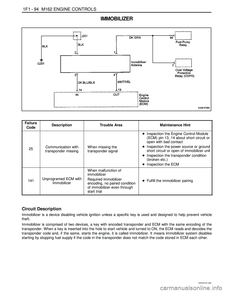
IMMOBILIZER
KAB1F360
Failure
CodeDescriptionTrouble AreaMaintenance Hint
25Communication with
transponder missingWhen missing the
transponder signal
DInspection the Engine Control Module
(ECM) pin 13, 14 about short circuit or
open with bad contact
DInspection the power source or ground
short circuit or open of immobilizer unit
DInspection the transponder condition
(broken etc.)
DInspection the ECM
141Unprogramed ECM with
immobilizer
When malfunction of
immobilizer
Required immobilizer
encoding, no paired condition
of immobilizer even through
start trial
DFulfill the immobilizer pairing
Circuit Description
Immobilizer is a device disabling vehicle ignition unless a specific key is used and designed to help prevent vehicle
theft.
Immobilizer is comprised of two devices, a key with encoded transponder and ECM with the same encoding of the
transponder. When a key is inserted into the hole to start vehicle and turned to ON, the ECM reads and decodes the
transponder code and, if the same, starts the engine, it is called immobilizer. It means immobilizersystem disables
starting by stopping fuel supply if the code in the transponder does not match the code stored in ECM each other.
Page 437 of 2053
M161 ENGINE CONTROLS 1F2 -- 15
D AEW OO M Y_2000
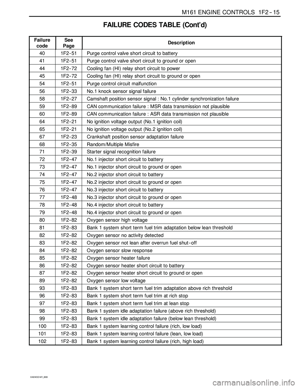
FAILURE CODES TABLE (Cont’d)
Failure
codeSee
PageDescription
401F2 -- 51Purge control valve short circuit to battery
411F2 -- 51Purge control valve short circuit to ground or open
441F2 -- 72Cooling fan (HI) relay short circuit to power
451F2 -- 72Cooling fan (HI) relay short circuit to ground or open
541F2 -- 51Purge control circuit malfunction
561F2 -- 33No.1 knock sensor signal failure
581F2 -- 27Camshaft position sensor signal : No.1 cylinder synchronization failure
591F2 -- 89CAN communication failure : MSR data transmission not plausible
601F2 -- 89CAN communication failure : ASR data transmission not plausible
641F2 -- 21No ignition voltage output (No.1 ignition coil)
651F2 -- 21No ignition voltage output (No.2 ignition coil)
671F2 -- 23Crankshaft position sensor adaptation failure
681F2 -- 35Random/Multiple Misfire
711F2 -- 39Starter signal recognition failure
721F2 -- 47No.1 injector short circuit to battery
731F2 -- 47No.1 injector short circuit to ground or open
741F2 -- 47No.2 injector short circuit to battery
751F2 -- 47No.2 injector short circuit to ground or open
761F2 -- 47No.3 injector short circuit to battery
771F2 -- 48No.3 injector short circuit to ground or open
781F2 -- 48No.4 injector short circuit to battery
791F2 -- 48No.4 injector short circuit to ground or open
801F2 -- 82Oxygen sensor high voltage
811F2 -- 83Bank 1 system short term fuel trim adaptation below lean threshold
821F2 -- 82Oxygen sensor no activity detected
831F2 -- 82Oxygen sensor not lean after overrun fuel shut -- off
841F2 -- 82Oxygen sensor slow response
851F2 -- 82Oxygen sensor heater failure
861F2 -- 82Oxygen sensor heater short circuit to battery
871F2 -- 82Oxygen sensor heater short circuit to ground or open
891F2 -- 82Oxygen sensor low voltage
931F2 -- 83Bank 1 system short term fuel trim adaptation above rich threshold
961F2 -- 83Bank 1 system short term fuel trim at rich stop
971F2 -- 83Bank 1 system short term fuel trim at lean stop
981F2 -- 83Bank 1 system idle adaptation failure (above rich threshold)
991F2 -- 83Bank 1 system idle adaptation failure (below lean threshold)
1001F2 -- 83Bank 1 system learning control failure (rich, low load)
1011F2 -- 83Bank 1 system learning control failure (lean, low load)
1021F2 -- 83Bank 1 system learning control failure (rich, high load)
Page 512 of 2053
1F2 -- 94 M161 ENGINE CONTROLS
D AEW OO M Y_2000
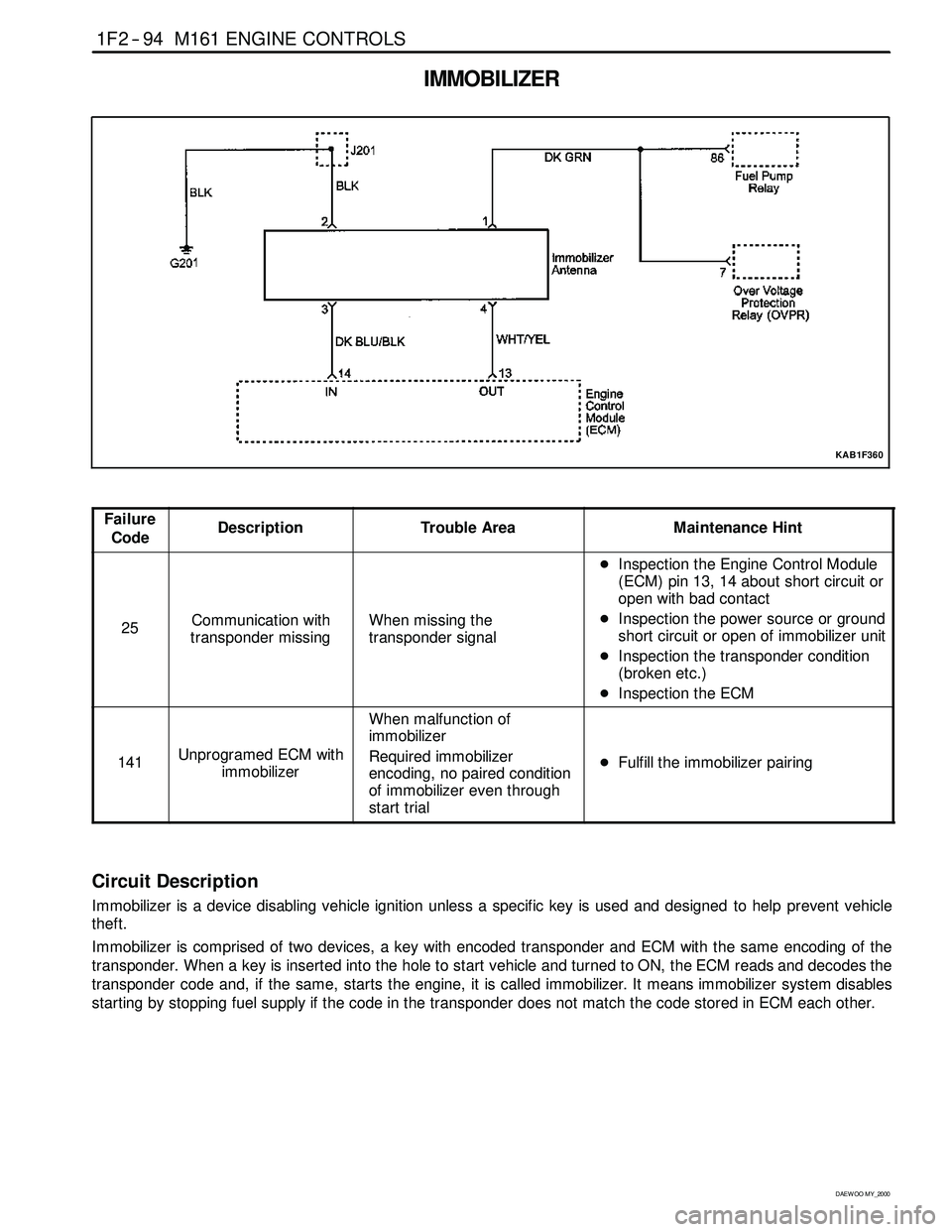
IMMOBILIZER
KAB1F360
Failure
CodeDescriptionTrouble AreaMaintenance Hint
25Communication with
transponder missingWhen missing the
transponder signal
DInspection the Engine Control Module
(ECM) pin 13, 14 about short circuit or
open with bad contact
DInspection the power source or ground
short circuit or open of immobilizer unit
DInspection the transponder condition
(broken etc.)
DInspection the ECM
141Unprogramed ECM with
immobilizer
When malfunction of
immobilizer
Required immobilizer
encoding, no paired condition
of immobilizer even through
start trial
DFulfill the immobilizer pairing
Circuit Description
Immobilizer is a device disabling vehicle ignition unless a specific key is used and designed to help prevent vehicle
theft.
Immobilizer is comprised of two devices, a key with encoded transponder and ECM with the same encoding of the
transponder. When a key is inserted into the hole to start vehicle and turned to ON, the ECM reads and decodes the
transponder code and, if the same, starts the engine, it is called immobilizer. It means immobilizersystem disables
starting by stopping fuel supply if the code in the transponder does not match the code stored in ECM each other.
Page 547 of 2053
1A3 -- 12 GENERAL ENGINE INFORMATION
D AEW OO M Y_2000
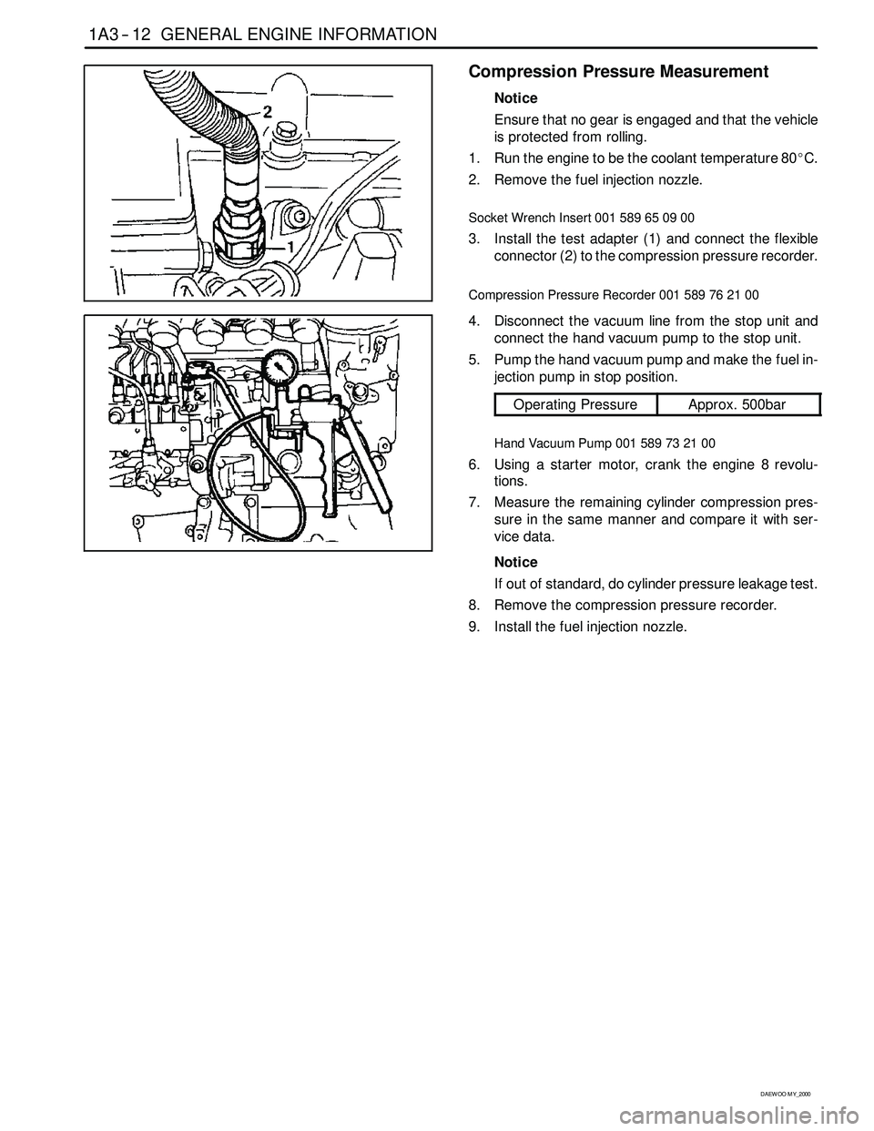
Compression Pressure Measurement
Notice
Ensure that no gear is engaged and that the vehicle
is protected from rolling.
1. Run the engine to be the coolant temperature 80_C.
2. Remove the fuel injection nozzle.
Socket Wrench Insert 001 589 65 09 00
3. Install the test adapter (1) and connect the flexible
connector (2) to the compression pressure recorder.
Compression Pressure Recorder 001 589 76 21 00
4. Disconnect the vacuum line from the stop unit and
connect the hand vacuum pump to the stop unit.
5. Pump the hand vacuum pump and make the fuel in-
jection pump in stop position.
Operating PressureApprox. 500bar
Hand Vacuum Pump 001 589 73 21 00
6. Using a starter motor, crank the engine 8 revolu-
tions.
7. Measure the remaining cylinder compression pres-
sure in the same manner and compare it with ser-
vice data.
Notice
If out of standard, do cylinder pressure leakage test.
8. Remove the compression pressure recorder.
9. Install the fuel injection nozzle.
Page 651 of 2053
1B3 -- 102 OM600 ENGINE MECHANICAL
D AEW OO M Y_2000
Checking
Notice
The noise which continues short time during short
travel (frequent starting of the engine) or engine
starting after a long time storage is normal operating
conditions. So, it does not need to be repaired. De-
termine the malfunctions in valve clearance com-
pensation device with noise through following tests.
If defective, replace as respectively.
1. Run the engine at more than 3000rpm for approx. 4
minutes.
2. Stop the engine. After 5minutes, check the engine
oil level and adjust if necessary.
3. Remove the cylinder head cover.
4. Check the valve tappets at TDC position of each cyl-
inders.
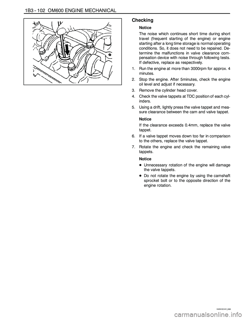
5. Using a drift, lightly press the valve tappet and mea-
sure clearance between the cam and valve tappet.
Notice
If the clearance exceeds 0.4mm, replace the valve
tappet.
6. If a valve tappet moves down too far in comparison
to the others, replace the valve tappet.
7. Rotate the engine and check the remaining valve
tappets.
Notice
DUnnecessary rotation of the engine will damage
the valve tappets.
DDo not rotate the engine by using the camshaft
sprocket bolt or to the opposite direction of the
engine rotation.
Page 774 of 2053

OM600 ENGINE CONTROLS 1F3 -- 17
D AEW OO M Y_2000
FUEL PUMP TEST
Notice
Before test, replace the fuel filter cartridge and fuel pre-
filter.
Fuel Feed Test
1. Disconnect the fuel return line (1) and seal up it with
plug.
2. Insert the plastic hose (5) and put the end into the
measuring beaker (6).
3. Disconnect the vacuum line (4) from vacuum unit
(engine stop) (5) and connect the vacuum pump (7)
to the vacuum unit.
4. To avoid the engine starting, build up vacuum
(approx. 500 mbar).
5. Operate the starter motor for exactly 30 seconds
and measure fuel volume in the beaker.
Min. volume150cm3for 30 seconds
Page 776 of 2053

OM600 ENGINE CONTROLS 1F3 -- 19
D AEW OO M Y_2000
Tools Required
617589042100 Tester
1. Disconnect the fuel line (2) from the fuel filter.
2. Remove the banjo bolt (4) from the fuel injection
pump and remove the seals (3) and fuel line (2).
3. Connect the tester (5).
4. Start the engine and read off the fuel pressure on
tester (5).
Notice
At Idle Speed> 0.3bar
At Full load> 0.5bar
If out of standard, replace the fuel feed pump.
Tester 617 589 04 21 00
5. Stop the engine.
6. Remove the tester.
7. Replace the seal and connect the fuel line (2).
Page 797 of 2053
1F3 -- 40 OM600 ENGINE CONTROLS
D AEW OO M Y_2000
Tools Required
617 589 09 21 00 Rl Sensor
617589102100 TimingTester
667589002100 TDCPulseGenerator
Commercial Tools
ItemTools
Digigal TesterWith Pulse GeneratorBosch, MOT 001.03gg
Hartmann & Braun, EOMT3
Without Pulse GeneratorBosch, ETD 019.00
Sun, DIT 9000
ALV, Diesel -- Tester 875
Test Procedure
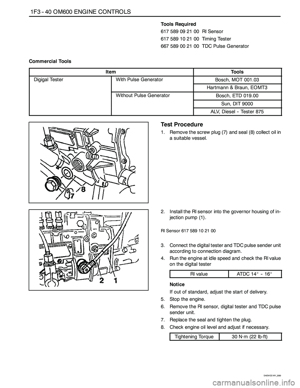
1. Remove the screw plug (7) and seal (8) collect oil in
a suitable vessel.
2. Install the Rl sensor into the governor housing of in-
jection pump (1).
Rl Sensor 617 589 10 21 00
3. Connect the digital tester and TDC pulse sender unit
according to connection diagram.
4. Run the engine at idle speed and check the Rl value
on the digital tester
Rl valueAT DC 1 4_-- 1 6_
Notice
If out of standard, adjust the start of delivery.
5. Stop the engine.
6. Remove the Rl sensor, digital tester and TDC pulse
sender unit.
7. Replace the seal and tighten the plug.
8. Check engine oil level and adjust if necessary.
Tightening Torque30 N∙m (22 lb-ft)