window SSANGYONG KORANDO 1997 Service User Guide
[x] Cancel search | Manufacturer: SSANGYONG, Model Year: 1997, Model line: KORANDO, Model: SSANGYONG KORANDO 1997Pages: 2053, PDF Size: 88.33 MB
Page 1778 of 2053

WINDNOISE 9J-3
SSANGYONG MY2002
MAINTENANCE AND REPAIR
ON-VEHICLE SERVICE
WINDNOISE REPAIR
Windnoise leak repairs are very similar to waterleak
repairs. Refer to Section 9I, Waterleaks. The actual
procedure depends on the type of seal being repaired.
Leaks around the door opening weatherstrips do not
al-ways indicate a faulty weatherstrip. A door or window
adjustment may resolve the condition. Refer to Section
9P, Doors or Section 9L, Glass and Mirrors.
Page 1783 of 2053

SECTION 9L
GLASS AND MIRRORS ON
CAUTION: Disconnect the negative battery cable before removing or installing any electrical unit or when a
tool or equipment could easily come in contact with exposed electrical terminals. Disconnecting this cable
will help prevent personal injury and damage to the vehicle. The ignition must also be in LOCK unless
otherwise noted.
TABLE OF CONTENTS
Description and Operation...................................9L-2
Stationary Glass..................................................9L-2
Inside Rearview Mirror.........................................9L-2
Outside Rearview Mirrors.....................................9L-2
Components Locator............................................9L-3
Glass and Mirror..................................................9L-3
Repair Instructions................................................9L-4
On-Vehicle Service Unit Repair................................9L-4
Windshield..........................................................9L-4
Rear Window Glass.............................................9L-6
Rear Window Defogger Braided Lead
Wire Repair......................................................9L-7Rear Window Defogger Grid Line Repair..............9L-8
Front Door Glass..................................................9L-9
Fixed Glass.........................................................9L-9
Inside Rearview Mirror ....................................... 9L-10
Outside Rearview Mirror..................................... 9L-10
Specifications.....................................................9L-11
Fastener Tightening Specifications..................... 9L-11
Schematic and Routing Diagram......................9L-12
Defroster........................................................... 9L-12
Inside Rear View Mirror (Dimming) &
Backup Lamp................................................. 9L-13
Page 1784 of 2053

SSANGYONG MY2002
9L-2 GLASS AND MIRRORS
DESCRIPTION AND OPERATION
STATIONARY GLASS
Stationary glass consists of all the glass on the vehicle
which is immovable within its frame, such as the wind
shield glass, the back glass, the quarter window, and
the inside rearview mirror.
INSIDE REARVIEW MIRROR
The inside rearview mirror can be manually adjusted
up/down, and left/right.
OUTSIDE REARVIEW MIRRORS
The outside rearview mirrors are equipped with a remote
control mirror. The electric control outside rearviewmirror
can be adjusted by an electric control switch on the
instrument panel
Page 1788 of 2053

SSANGYONG MY2002
9L-6 GLASS AND MIRRORS
KAA9L080
KAA9L090
KAA9L100
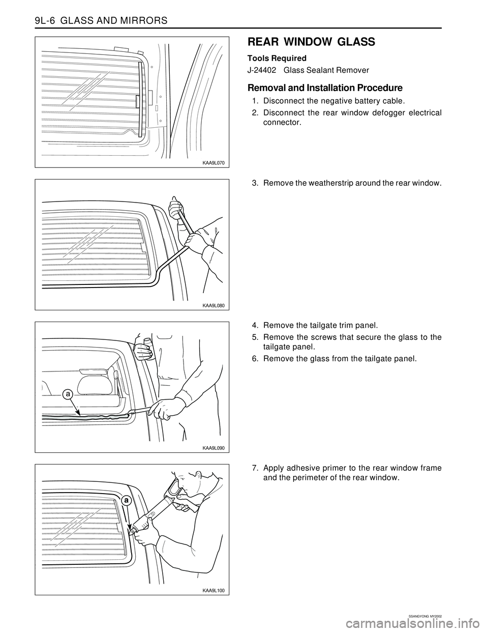
3. Remove the weatherstrip around the rear window.
7. Apply adhesive primer to the rear window frame
and the perimeter of the rear window.
KAA9L070
REAR WINDOW GLASS
Tools Required
J-24402Glass Sealant Remover
Removal and Installation Procedure
1. Disconnect the negative battery cable.
2. Disconnect the rear window defogger electrical
connector.
4. Remove the tailgate trim panel.
5. Remove the screws that secure the glass to the
tailgate panel.
6. Remove the glass from the tailgate panel.
Page 1789 of 2053

GLASS AND MIRRORS 9L-7
SSANGYONG MY2002
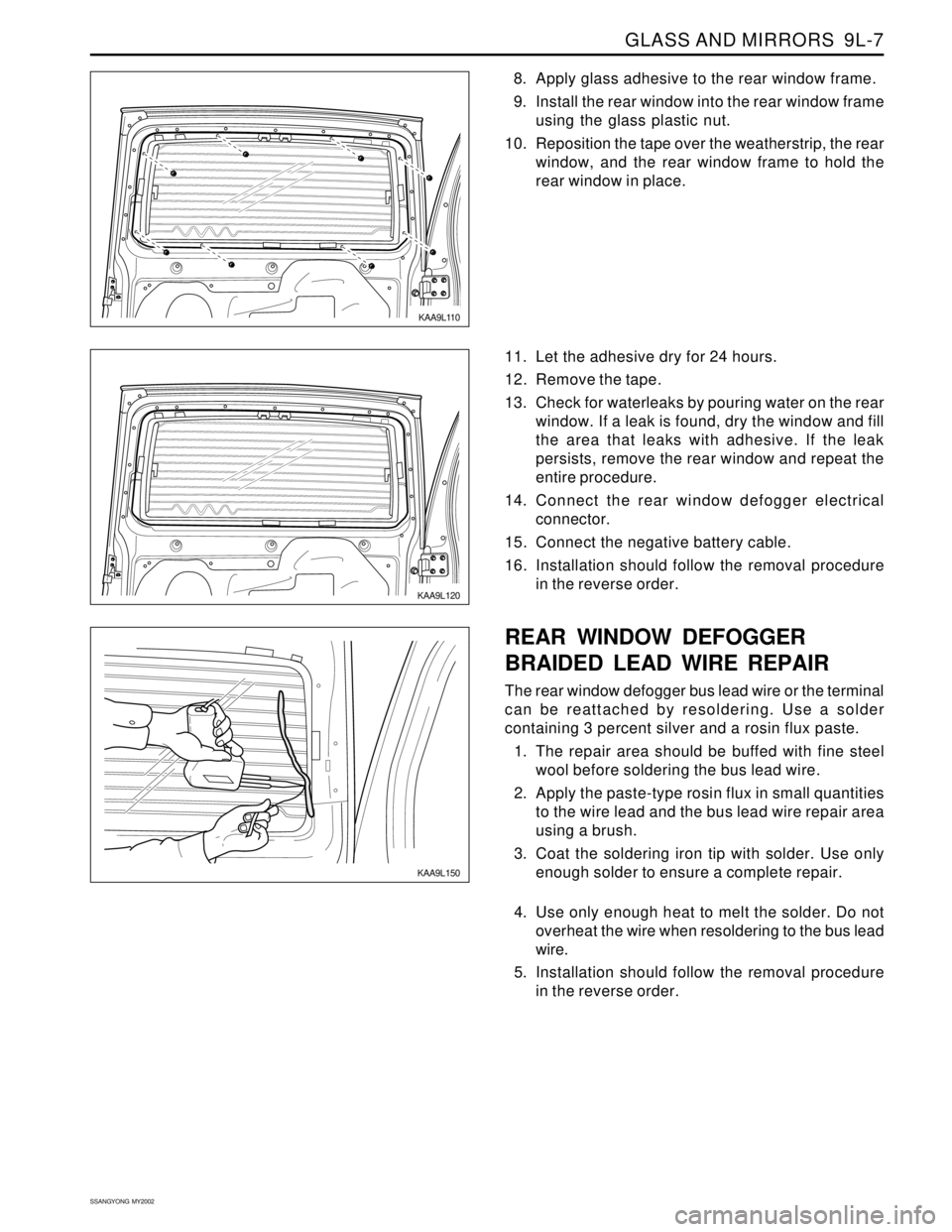
KAA9L120
11. Let the adhesive dry for 24 hours.
12. Remove the tape.
13. Check for waterleaks by pouring water on the rear
window. If a leak is found, dry the window and fill
the area that leaks with adhesive. If the leak
persists, remove the rear window and repeat the
entire procedure.
14. Connect the rear window defogger electrical
connector.
15. Connect the negative battery cable.
16. Installation should follow the removal procedure
in the reverse order.
KAA9L110
8. Apply glass adhesive to the rear window frame.
9. Install the rear window into the rear window frame
using the glass plastic nut.
10. Reposition the tape over the weatherstrip, the rear
window, and the rear window frame to hold the
rear window in place.
KAA9L150
REAR WINDOW DEFOGGER
BRAIDED LEAD WIRE REPAIR
The rear window defogger bus lead wire or the terminal
can be reattached by resoldering. Use a solder
containing 3 percent silver and a rosin flux paste.
1. The repair area should be buffed with fine steel
wool before soldering the bus lead wire.
2. Apply the paste-type rosin flux in small quantities
to the wire lead and the bus lead wire repair area
using a brush.
3. Coat the soldering iron tip with solder. Use only
enough solder to ensure a complete repair.
4. Use only enough heat to melt the solder. Do not
overheat the wire when resoldering to the bus lead
wire.
5. Installation should follow the removal procedure
in the reverse order.
Page 1790 of 2053

SSANGYONG MY2002
9L-8 GLASS AND MIRRORS
KAA9L140
Notice: The grid line repair material must be cured
with heat. In order to avoid heat damage to the
interior trim, protect the trim near the repair area
where heat will be applied.
9. Heat the repair area for 1 to 2 minutes.
10. Hold the heat gun nozzle 25 mm (1 inch) from the
surface. A minimum temperature of 149°C (300°F)
is required.
11. Inspect the grid line repair area. If the repair
appears discolored, apply a coating of tincture of
iodine to the area using a pipe cleaner or a line
brush. Allow the iodine to dry for about 30
seconds. Carefully wipe off the excess iodine with
a lint-free cloth.
12. Test the operation of the rear window defogger in
order to verify that the repair was successful.
Important: At least 24 hours is required for
complete curing of the repair materials. The repair
area should not be physically disturbed until after
that time.
13. Installation should follow the removal procedure
in the reverse order.
KAA9L130
REAR WINDOW DEFOGGER GRID
LINE REPAIR
1. Disconnect the negative battery cable.
2. Disconnect the rear window defogger electrical
connector.
3. Inspect the rear window defogger grid lines.
4. Mark the grid line break on the outside of the glass
with a wax pencil or a crayon.
5. Buff the grid lines that are to be repaired with steel
wool. Wipe the lines clean using a cloth dampened
with alcohol. Buff and clean about 6 mm (0.25 inch)
beyond each side of the break in the grid line.
KAA9L130
6. Attach a grid line repair decal or two strips of tape
above and below the repair areas.
A repair decal or tape must be used in order to
control the width of the repair areas.
If a decal is used, the die-cut metered slot must
be the same width as the grid line.
7. Apply the grid repair material to the repair area
using a small wooden stick or a spatula. The grid
repair material should be at room temperature.
8. Carefully remove the decal or the tape.
Page 1791 of 2053

GLASS AND MIRRORS 9L-9
SSANGYONG MY2002
KAA9L160
KAA9L170
FRONT DOOR GLASS
Removal Procedure
1. Remove the door seal trim. Refer to Section 9P,
Doors.
2. Remove the screws that secure the glass to the
window regulator.
3. Remove the glass from the door.
4. Removal procedure should follow the installation
procedure in the reverse order.
Installation Procedure
1. Install the glass in the door and position the glass
within the window regulator.
Notice: Dissimilar metals in direct contact with
each other may corrode rapidly. Make sure to use
the correct fasteners to prevent premature
corrosion.
2. Install the glass to the window regulator with the
screws.
Installation Notice
3. Install the door seal trim. Refer to Section 9P,
Doors.
4. Removal procedure should follow the installation
procedure in the reverse order.
Tightening Torque1.96 - 2.94 Nm
(17.50 - 26.25 lb-in)
KAA9L180
FIXED GLASS
Removal and Installation Procedure
1. Remove the exterior B-pillar molding. Refer to
Section 9M, Exterior Trim.
2. Remove the screws that secure the glass to the
window regulator.
3. Remove the glass from the door.
Installation Notice
Dissimilar metals in direct contact with each
other may corrode rapidly. Make sure to use
the correct fasteners to prevent premature
corrosion.
4. Installation should follow the removal procedure
in the reverse order.
Tightening Torque 7 Nm (62 lb-in)
Page 1819 of 2053

SECTION 9P
DOORS
CAUTION: Disconnect the negative battery cable before removing or installing any electrical unit or when a
tool or equipment could easily come in contact with exposed electrical terminals. Disconnecting this cable
will help prevent personal injury and damage to the vehicle. The ignition must also be in LOCK unless
otherwise noted.
TABLE OF CONTENTS
Description and Operation...................................9P-2
Power Door Locks................................................9P-2
Power Windows...................................................9P-2
Door Lock Striker.................................................9P-2
Components Locator............................................9P-3
Doors ..................................................................9P-3
Repair Instructions................................................9P-4
On-Vehicle Service Unit Repair................................9P-4
Door Glass Run...................................................9P-4
Door Side Opening Weatherstrip..........................9P-4
Door Lock Striker.................................................9P-4
Door Lock Striker Adjustment...............................9P-5
Front Door Lock...................................................9P-6
Inside Door Handle..............................................9P-7
Outside Door Handle ...........................................9P-7Door Lock Cylinder..............................................9P-7
Power Window Regulator.....................................9P-8
Front Door Assembly ...........................................9P-8
Tail Gate Assembly.............................................9P-8
Door Hinge..........................................................9P-9
Door Hold Open Link ...........................................9P-9
Outside Channel Molding.....................................9P-9
Door Weatherstrip................................................9P-9
Door Seal Trim...................................................9P-10
Specifications.....................................................9P-11
Fastener Tightening Specifications.....................9P-11
Schematic and Routing Diagrams.....................9P-12
Central Door Locks System................................9P-12
Power Windows.................................................9P-13
Page 1820 of 2053

SSANGYONG MY2002
9P-2 DOORS
DESCRIPTION AND OPERATION
POWER DOOR LOCKS
The power door locks use a solenoid that is contained
in each door lock assembly. The door locks are
activated by the actuator on the inside door handle or
by the lock cylinder on the driver’s side door only.
When the driver’s side door is locked or unlocked by
the actuator or lock cylinder, all doors are locked or
unlocked accordingly.
POWER WINDOWS
The power windows are controlled by electrical
switches on the door trim center upper panel and areoperated by a motor at each window regulator. The
windows are lowered by pressing the switch and are
raised by pulling up on the switch. The window will
stop movement when the switch is released or when
the windowis completely open or closed.
DOOR LOCK STRIKER
The front door lock strikers each consist of a striker
with two screws threaded into a floating cage plate in
the B-pillars. The door lock fork snaps over and engages
the striker.
Page 1821 of 2053

SSANGYONG MY2002
9P-4 DOORS
DOOR LOCK STRIKER
Removal and Installation Procedure
1. Remove the screws and the door lock striker.
Installation Notice
Dissimilar metals in direct contact with each
other may corrode rapidly. Make sure to use
the correct fasteners to prevent premature
corrosion.
2. Installation should follow the removal procedure
in the reverse order.
KAA9P020
ON-VEHICLE SERVICE
UNIT REPAIR
DOOR GLASS RUN
Removal and Installation Procedure
1. Lower the window.
2. Remove the glass from the door.
3. Remove the front door glass run.
4. Installation should follow the removal procedure
in the reverse order.
REPAIR INSTRUCTIONS
KAA9P030
DOOR SIDE OPENING
WEATHERSTRIP
Removal and Installation Procedure
1. Remove the side opening weatherstrip.
2. Installation should follow the removal procedure
in the reverse order.
Tightening Torque9.8 - 18.62 Nm
(7.23 - 13.74 lb-ft)
KAA9P040