checking oil SSANGYONG KORANDO 1997 Service Repair Manual
[x] Cancel search | Manufacturer: SSANGYONG, Model Year: 1997, Model line: KORANDO, Model: SSANGYONG KORANDO 1997Pages: 2053, PDF Size: 88.33 MB
Page 651 of 2053
1B3 -- 102 OM600 ENGINE MECHANICAL
D AEW OO M Y_2000
Checking
Notice
The noise which continues short time during short
travel (frequent starting of the engine) or engine
starting after a long time storage is normal operating
conditions. So, it does not need to be repaired. De-
termine the malfunctions in valve clearance com-
pensation device with noise through following tests.
If defective, replace as respectively.
1. Run the engine at more than 3000rpm for approx. 4
minutes.
2. Stop the engine. After 5minutes, check the engine
oil level and adjust if necessary.
3. Remove the cylinder head cover.
4. Check the valve tappets at TDC position of each cyl-
inders.
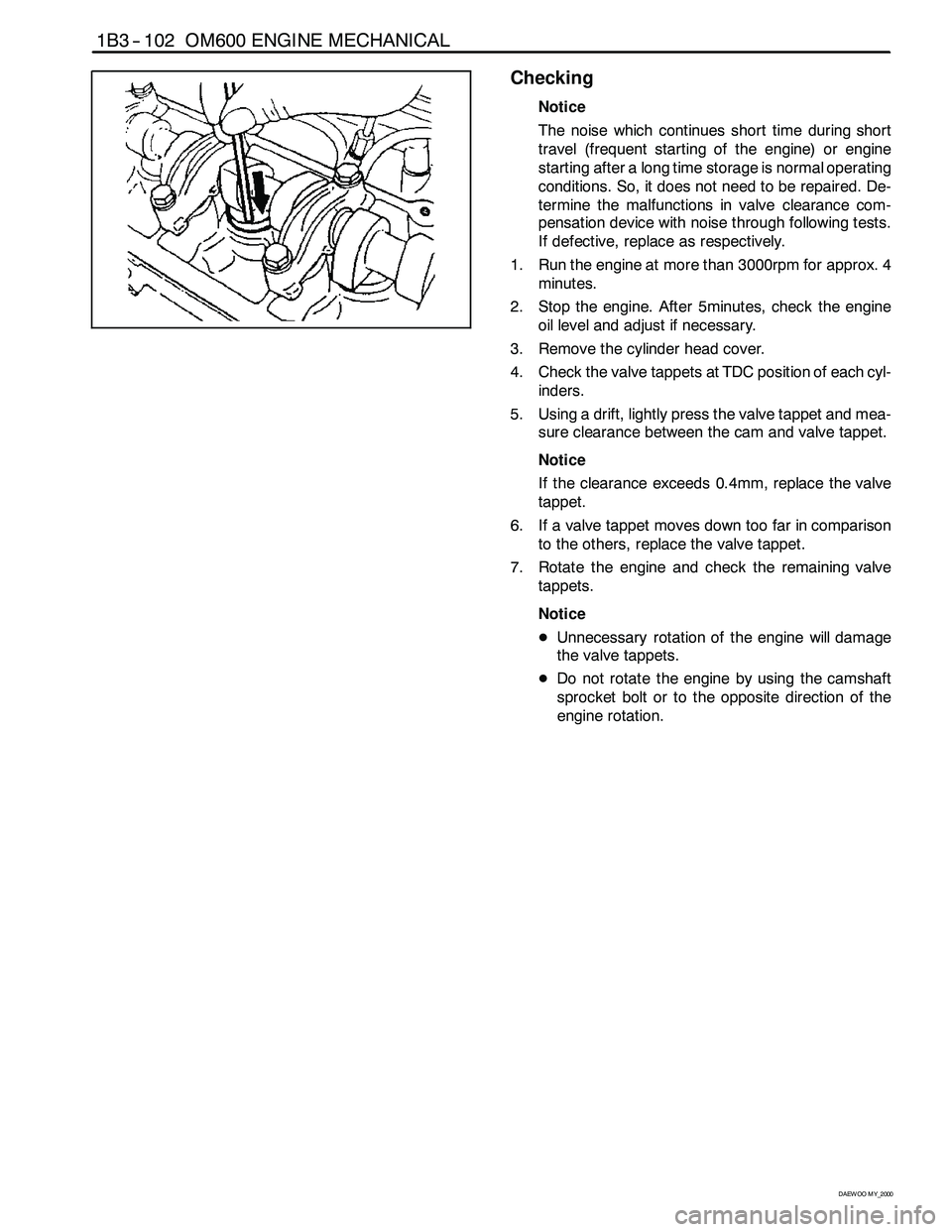
5. Using a drift, lightly press the valve tappet and mea-
sure clearance between the cam and valve tappet.
Notice
If the clearance exceeds 0.4mm, replace the valve
tappet.
6. If a valve tappet moves down too far in comparison
to the others, replace the valve tappet.
7. Rotate the engine and check the remaining valve
tappets.
Notice
DUnnecessary rotation of the engine will damage
the valve tappets.
DDo not rotate the engine by using the camshaft
sprocket bolt or to the opposite direction of the
engine rotation.
Page 1132 of 2053
5A-38 AUTOMATIC TRANSMISSION
SSANGYONG MY2002
DIAGNOSIS
BASIC KNOWLEDGE REQUIRED
You must be familliar with some basic electronics to
use this section of the Service Manual. They will help
you to follow diagnostic procedures.
Notice: Lack of the basic knowledge of this transmis-
sion when performing diagnostic procedures could re-
sult in incorrect diagnostic performance or damage to
transmission components. Do not, under any circum-
stances, attempt to diagnose a transmission problem
without this basic knowledge.
Notice: If a wire is probed with a sharp instrument
and not properly sealed afterward, the wire will corrode
and an open circuit will result.
Diagnostic test probes are now available that allow
you to probe individual wires without leaving the wire
open to the environment. These probe devices are
inexpensive and easy to install, and they permanently
seal the wire from corrosion.
Special Tools
You should be able to use a Digital Volt Meter (DVM),
a circuit tester, jumper wires or leads and a line
pressure gauge set. The functional check procedure
is designed to verify the correct operation of electronic
components in the transmission. This will eliminate the
unnecessary removal of transmission components.
FUNCTIONAL CHECK
PROCEDURE
Begin with the Functional Check Procedure which pro-
vides a general outline of how to diagnose automatic
transmission. The following functional check procedure
will indicate the proper path of diagnosing the transmis-
sion by describing the basic checks and then referenc-
ing the locations of the specific checks.
Check the fluid level according to the Fluid Level
Service Procedure.
Check the transmission fluid leak.
Check if the transmission fluid is not burnt by smell.
Notice: The specific fluid used in this transmission
turns brown during normal operation. Brown fluid
does not indicate a transmission fault.
Ensure that the transmission is not in Limp Home
Mode (LHM).
Check the battery terminals and the earth connec-
tions for corrosion or looseness.
Check that the cooler flow is not restricted.
Check all electrical plug connections for tightness.
Use on-board diagnostic tool or a scan tool to see
if any transmission trouble codes have been set.
DIAGNOSTIC INFORMATION AND PROCEDURES
Refer to the appropriate “Diagnostic Trouble Code
(DTC)” information and repair the vehicle as
directed. After repairing the vehicle, perform the
road test and verify that the code has not set again.
Perform the Electrical/Garage Shift Tests.
Perform the Road Test Procedure in this section.
Inspect the oil and check for metal or other contami-
nants in the oil pan.
TRANSMISSION FLUID LEVEL
SERVICE PROCEDURE
This procedure is to be used when checking a concern
with the fluid level in a vehicle. A low fluid level will
result in slipping and loss of drive/ reverse or delay on
engagement of drive/ reverse when the vehicle is cold.
The vehicle is first checked for transmission diagnostic
messages on the scan tool. If the oil level is low, it is
possible to register a vehicle speed signal fault.
The vehicle is to be test driven to determine if there is
an abnormal delay when selecting drive or reverse, or
loss of drive. One symptom of low fluid level is a
momentary loss of drive when driving the vehicle around
a corner. Also when the transmission fluid level is low,
a loss of drive may occur when the transmission fluid
temperature is low.
If there is no loss of drive when the vehicle is driven
warm and a vehicle speed signal fault is registered,
then fluid should be added to the transmission.
When adding or changing transmission fluid use only
Castrol TQ 95 automatic transmission fluid. The use of
incorrect fluid will cause the performance and durability
of the transmission to be severely degraded.
Fluid Level Diagnosis procedure
1. If the vehicle is at operating temperature allow the
vehicle to cool down for two hours, but no greater
than four hours. Or if the vehicle is at cool status,
start the engine and allow the engine to idle for
approximately 5 minutes or, if possible, drive the
vehicle for a few kilometers. This will allow the
transmission to be within the correct temperature
range. Transmission fluid level should be checked
at temperature 50 - 60 °C (82 - 140 °F).
Caution: Removal of the fluid filler plug when
the transmission fluid is hot may cause injury if
fluid drains from the filler hole.
2. With the brake pedal pressed, move the gear shift
control lever through the gear ranges, pausing a
few seconds in each range. Return the gear shift
control lever to P (Park). Turn the engine OFF.
3. Park the vehicle on a hoist, inspection pit or similar
raised level surface. The vehicle must be control
level to obtain a correct fluid level measurement.
Page 1446 of 2053
SSANGYONG MY2002
6A-4 POWER STEERING SYSTEM
KAA6A020
DIAGNOSTIC INFORMATION AND PROCEDURES
POWER STEERING SYSTEM
PRESSURE TEST
Tools Required
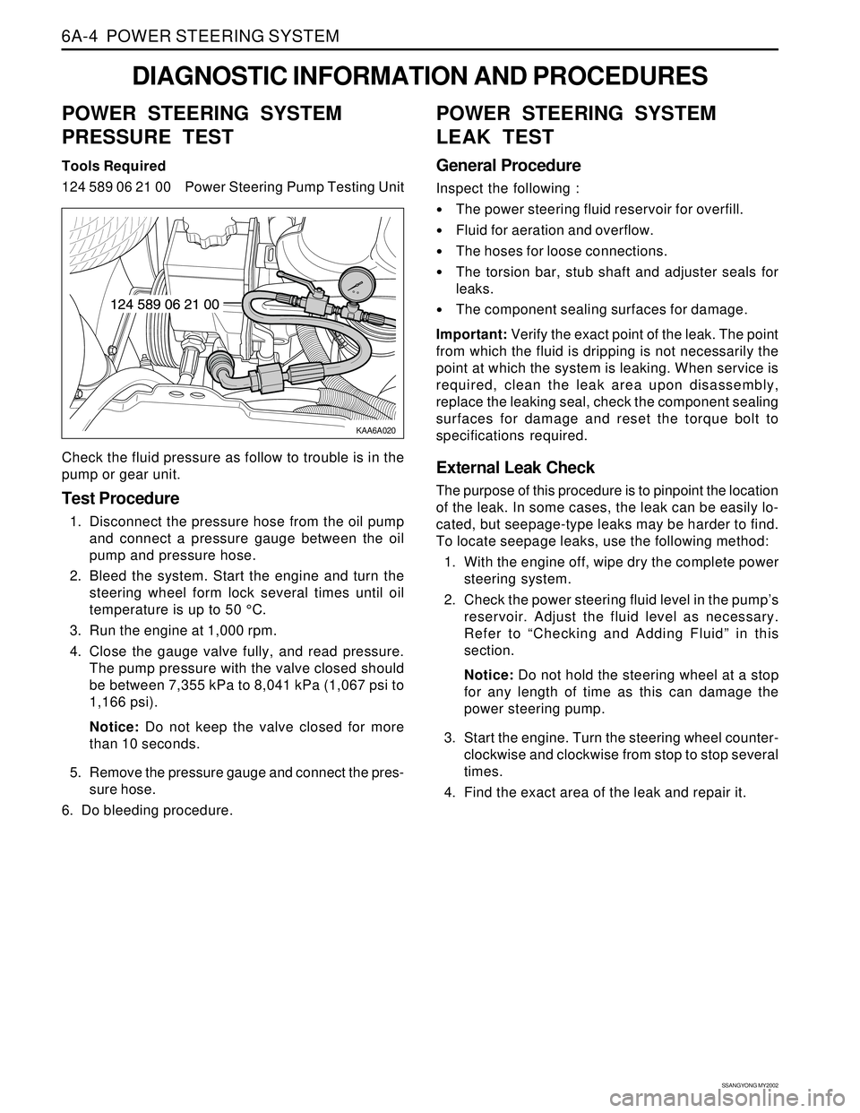
124 589 06 21 00 Power Steering Pump Testing Unit
Check the fluid pressure as follow to trouble is in the
pump or gear unit.
Test Procedure
1. Disconnect the pressure hose from the oil pump
and connect a pressure gauge between the oil
pump and pressure hose.
2. Bleed the system. Start the engine and turn the
steering wheel form lock several times until oil
temperature is up to 50 °C.
3. Run the engine at 1,000 rpm.
4. Close the gauge valve fully, and read pressure.
The pump pressure with the valve closed should
be between 7,355 kPa to 8,041 kPa (1,067 psi to
1,166 psi).
Notice: Do not keep the valve closed for more
than 10 seconds.
5. Remove the pressure gauge and connect the pres-
sure hose.
6. Do bleeding procedure.
POWER STEERING SYSTEM
LEAK TEST
General Procedure
Inspect the following :
The power steering fluid reservoir for overfill.
Fluid for aeration and overflow.
The hoses for loose connections.
The torsion bar, stub shaft and adjuster seals for
leaks.
The component sealing surfaces for damage.
Important: Verify the exact point of the leak. The point
from which the fluid is dripping is not necessarily the
point at which the system is leaking. When service is
required, clean the leak area upon disassembly,
replace the leaking seal, check the component sealing
surfaces for damage and reset the torque bolt to
specifications required.
External Leak Check
The purpose of this procedure is to pinpoint the location
of the leak. In some cases, the leak can be easily lo-
cated, but seepage-type leaks may be harder to find.
To locate seepage leaks, use the following method:
1. With the engine off, wipe dry the complete power
steering system.
2. Check the power steering fluid level in the pump’s
reservoir. Adjust the fluid level as necessary.
Refer to “Checking and Adding Fluid” in this
section.
Notice: Do not hold the steering wheel at a stop
for any length of time as this can damage the
power steering pump.
3. Start the engine. Turn the steering wheel counter-
clockwise and clockwise from stop to stop several
times.
4. Find the exact area of the leak and repair it.
Page 1447 of 2053
POWER STEERING SYSTEM 6A-5
SSANGYONG MY2002
BLEEDING THE POWER
STEERING SYSTEM
1. Disconnect the fuel line. Using a starter motor,
crank the engine and turn the steering wheel from
lock to start 5 or 6 times.
Notice: Do bleeding with engine cranking. If bleed
with idling, there can be a air contact with oil.
2. Connect the fuel feed line and start the engine at
idle speed.
3. Turn the steering wheel from lock to lock until there
is no more air in oil reservoir.
4. Connect the oil level is within specification.
5. By turning the steering wheel left to right, check
the oil level change.
Notice: If oil is not changes more than 5 mm, do
bleeding again. If oil level rises suddenly when
stopped engine, again.
MAINTENANCE
CHECKING AND ADDING FLUID
Notice: When adding fluid or making a complete fluid
change, always use DEXRON. - II power steering fluid.
Failure to use the proper fluid will cause hose and seal
damage and fluid leaks.
1. The power steering fluid level is indicated by marks
on a fluid level indicator on the fluid reservoir cap.
2. If the fluid is warmed up to 66 °C (150 °F), the fluid
level should be between the MAX and MIN marks.
Add fluid as needed.
3. If the fluid is cool, 21 °C (70 °F), the fluid level should
be at the MIN mark. Add fluid as needed.
Page 1455 of 2053
SSANGYONG MY2002
6A-4 POWER STEERING SYSTEM
KAA6A020
DIAGNOSTIC INFORMATION AND PROCEDURES
POWER STEERING SYSTEM
PRESSURE TEST
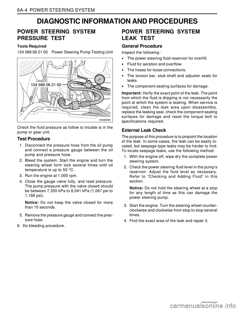
Tools Required
124 589 06 21 00 Power Steering Pump Testing Unit
Check the fluid pressure as follow to trouble is in the
pump or gear unit.
Test Procedure
1. Disconnect the pressure hose from the oil pump
and connect a pressure gauge between the oil
pump and pressure hose.
2. Bleed the system. Start the engine and turn the
steering wheel form lock several times until oil
temperature is up to 50 °C.
3. Run the engine at 1,000 rpm.
4. Close the gauge valve fully, and read pressure.
The pump pressure with the valve closed should
be between 7,355 kPa to 8,041 kPa (1,067 psi to
1,166 psi).
Notice: Do not keep the valve closed for more
than 10 seconds.
5. Remove the pressure gauge and connect the pres-
sure hose.
6. Do bleeding procedure.
POWER STEERING SYSTEM
LEAK TEST
General Procedure
Inspect the following :
The power steering fluid reservoir for overfill.
Fluid for aeration and overflow.
The hoses for loose connections.
The torsion bar, stub shaft and adjuster seals for
leaks.
The component sealing surfaces for damage.
Important: Verify the exact point of the leak. The point
from which the fluid is dripping is not necessarily the
point at which the system is leaking. When service is
required, clean the leak area upon disassembly,
replace the leaking seal, check the component sealing
surfaces for damage and reset the torque bolt to
specifications required.
External Leak Check
The purpose of this procedure is to pinpoint the location
of the leak. In some cases, the leak can be easily lo-
cated, but seepage-type leaks may be harder to find.
To locate seepage leaks, use the following method:
1. With the engine off, wipe dry the complete power
steering system.
2. Check the power steering fluid level in the pump’s
reservoir. Adjust the fluid level as necessary.
Refer to “Checking and Adding Fluid” in this
section.
Notice: Do not hold the steering wheel at a stop
for any length of time as this can damage the
power steering pump.
3. Start the engine. Turn the steering wheel counter-
clockwise and clockwise from stop to stop several
times.
4. Find the exact area of the leak and repair it.
Page 1456 of 2053
POWER STEERING SYSTEM 6A-5
SSANGYONG MY2002
BLEEDING THE POWER
STEERING SYSTEM
1. Disconnect the fuel line. Using a starter motor,
crank the engine and turn the steering wheel from
lock to start 5 or 6 times.
Notice: Do bleeding with engine cranking. If bleed
with idling, there can be a air contact with oil.
2. Connect the fuel feed line and start the engine at
idle speed.
3. Turn the steering wheel from lock to lock until there
is no more air in oil reservoir.
4. Connect the oil level is within specification.
5. By turning the steering wheel left to right, check
the oil level change.
Notice: If oil is not changes more than 5 mm, do
bleeding again. If oil level rises suddenly when
stopped engine, again.
MAINTENANCE
CHECKING AND ADDING FLUID
Notice: When adding fluid or making a complete fluid
change, always use DEXRON. - II power steering fluid.
Failure to use the proper fluid will cause hose and seal
damage and fluid leaks.
1. The power steering fluid level is indicated by marks
on a fluid level indicator on the fluid reservoir cap.
2. If the fluid is warmed up to 66 °C (150 °F), the fluid
level should be between the MAX and MIN marks.
Add fluid as needed.
3. If the fluid is cool, 21 °C (70 °F), the fluid level should
be at the MIN mark. Add fluid as needed.
Page 1547 of 2053

SSANGYONG MY2002
7C-18 MANUAL & SEMIAUTO-HVAC
Total Oil Capacity 265 cc
COMPRESSOR OIL
REPLACEMENT
Before Oil Replacement
When any part is replaced or there are a lot of gas
leaks in the A/C system, you should add the specified
amount of the oil to keep the approval oil capacity
because the oil for lubricating the compressor
circulates through the A/C system during operating
the compressor.
Handling Oil
Be careful that moistures, dusts etc. must not flow
into the oil.
Do not mix with any other material.
If the oil leaves outside for long time, it’s possible
to mix it with the moistures and so keep the oil
sealed with a container.
Circulating Oil
For checking or adjusting the oil level, set the control
unit to full cold and max blower speed with keeping
the engine run at idle for 20 - 30 minutes in order to
circulate the oil through the compressor.