STARTING SSANGYONG KORANDO 1997 Service Owner's Manual
[x] Cancel search | Manufacturer: SSANGYONG, Model Year: 1997, Model line: KORANDO, Model: SSANGYONG KORANDO 1997Pages: 2053, PDF Size: 88.33 MB
Page 890 of 2053

PROPELLER SHAFT 3C-3
SSANGYONG MY2002
PROPELLER SHAFT
Inspection Procedure
1. Visually check the propeller shaft.
2. Using a dial indicator, measure propeller shaft
runout by turning the shaft. If runout exceeds limit,
replace the propeller shaft or correct it.
Adjustment Notice
DIAGNOSTIC INFORMATION AND PROCEDURES
KAA3C020
Specification 0.4 mm (0.016 inch)
3. Measure the universal joint starting torque.
Adjustment Notice
Specification 0.54 N•m (4.78 lb-in)
KAA3C030
4. Measure the spider outer diameter.
Adjustment Notice
Specification 16.668 mm (0.656 inch)
KAA3C040
4. Measure the spider outer diameter.
Adjustment Notice
Specification 0.064 mm (0.0025 inch)
KAA3C050
Page 998 of 2053
ABS AND TCS 4F-15
SSANGYONG MY2002
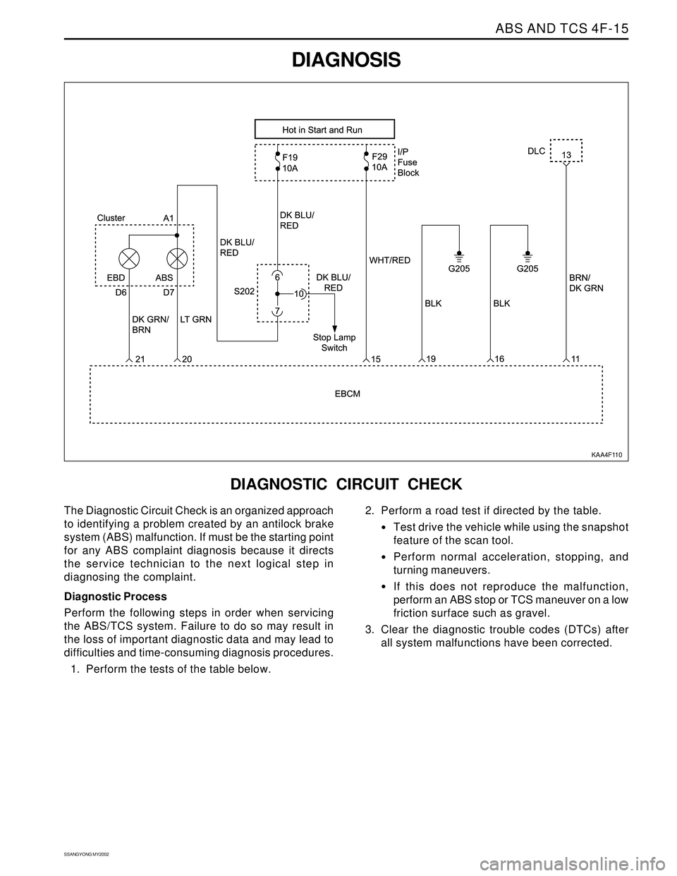
DIAGNOSIS
KAA4F110
DIAGNOSTIC CIRCUIT CHECK
The Diagnostic Circuit Check is an organized approach
to identifying a problem created by an antilock brake
system (ABS) malfunction. If must be the starting point
for any ABS complaint diagnosis because it directs
the service technician to the next logical step in
diagnosing the complaint.
Diagnostic Process
Perform the following steps in order when servicing
the ABS/TCS system. Failure to do so may result in
the loss of important diagnostic data and may lead to
difficulties and time-consuming diagnosis procedures.
1. Perform the tests of the table below.2. Perform a road test if directed by the table.
Test drive the vehicle while using the snapshot
feature of the scan tool.
Perform normal acceleration, stopping, and
turning maneuvers.
If this does not reproduce the malfunction,
perform an ABS stop or TCS maneuver on a low
friction surface such as gravel.
3. Clear the diagnostic trouble codes (DTCs) after
all system malfunctions have been corrected.
Page 1096 of 2053
5A-2 AUTOMATIC TRANSMISSION
SSANGYONG MY2002
OPERATORS INTERFACES
There are three operator interfaces as the following;
•Gear Shift Control Lever
Driving Mode Selector
Indicator Light
Gear Shift Control lever
The transmission uses a conventional shift control lever.
The gear shift control lever can be moved from one
position to another within the staggered configuration
of the shift control lever gate to positively indicate the
gear selection.
DESCRIPTION AND OPERATION
BTRA M74 4WD AUTOMATIC
TRANSMISSION
The BTR Automotive Model 74 Four Speed Automatic
Transmission is an electronically controlled overdrive
four speed unit with a lock-up torque converter. The
lock-up torque converter results in lower engine speeds
at cruise and eliminates unnecessary slippage. These
features benefit the customer through improved fuel
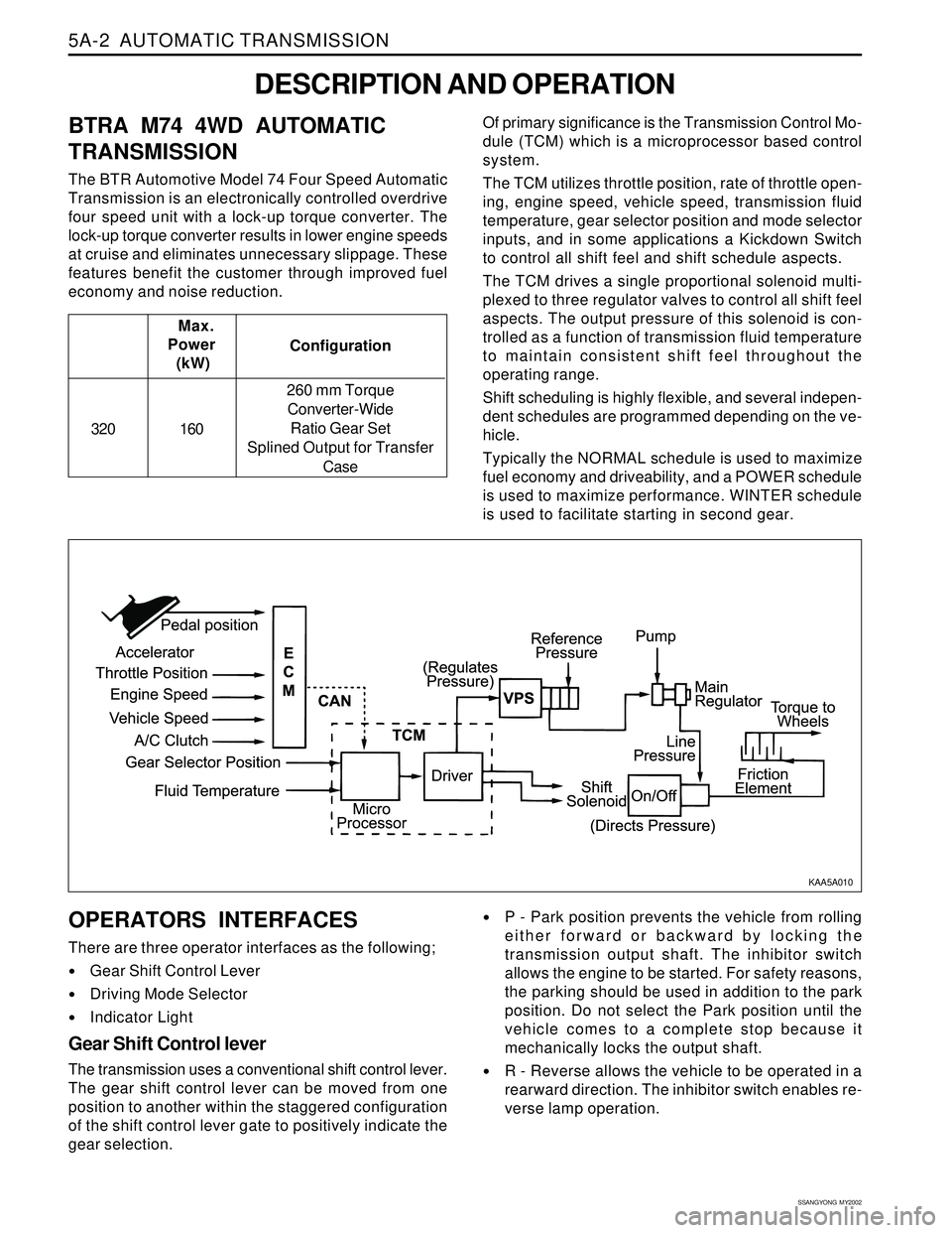
economy and noise reduction.Of primary significance is the Transmission Control Mo-
dule (TCM) which is a microprocessor based control
system.
The TCM utilizes throttle position, rate of throttle open-
ing, engine speed, vehicle speed, transmission fluid
temperature, gear selector position and mode selector
inputs, and in some applications a Kickdown Switch
to control all shift feel and shift schedule aspects.
The TCM drives a single proportional solenoid multi-
plexed to three regulator valves to control all shift feel
aspects. The output pressure of this solenoid is con-
trolled as a function of transmission fluid temperature
to maintain consistent shift feel throughout the
operating range.
Shift scheduling is highly flexible, and several indepen-
dent schedules are programmed depending on the ve-
hicle.
Typically the NORMAL schedule is used to maximize
fuel economy and driveability, and a POWER schedule
is used to maximize performance. WINTER schedule
is used to facilitate starting in second gear. Configuration Max.
Power
(kW)
320 160260 mm Torque
Converter-Wide
Ratio Gear Set
Splined Output for Transfer
Case
P - Park position prevents the vehicle from rolling
either forward or backward by locking the
transmission output shaft. The inhibitor switch
allows the engine to be started. For safety reasons,
the parking should be used in addition to the park
position. Do not select the Park position until the
vehicle comes to a complete stop because it
mechanically locks the output shaft.
R - Reverse allows the vehicle to be operated in a
rearward direction. The inhibitor switch enables re-
verse lamp operation.
KAA5A010
Page 1097 of 2053

AUTOMATIC TRANSMISSION 5A-3
SSANGYONG MY2002
N - Neutral allows the engine to be started and oper-
ated while driving the vehicle. The inhibitor switch
allows the engine to be started. There is no power
transferred through the transmission in Neutral. But
the final drive is not locked by the parking pawl, so
thewheels are free to rotate.
D - Overdrive range is used for all normal driving
conditions. 4th gear (overdrive gear) reduces the
fuel consumption and the engine noise. Engine
braking is applied with reduced throttle.
First to second (1 → 2), first to third (1 → 3), second
to third (2 → 3), second to fourth (2 → 4), third to
fourth (3 → 4), fourth to third (4 → 3), fourth to
second (4 → 2), third to second (3 → 2), third to
first (3 → 1) and second to first (2 → 1) shifts are
all available as a function of vehicle speed, throttle
position and the time change rate of the throttle
position.
Downshifts are available for safe passing by
depress-ing the accelerator. Lockup clutch may be
enabled in 3rd and 4th gears depending on vehicle
type.
3 - Manual 3 provides three gear ratios (first through
third) and prevents the transmission from operating
in 4th gear. 3rd gear is used when driving on long
hill roads or in heavy city traffic. Downshifts are
available by depressing the accelerator.
2 - Manual 2 provides two gear ratios (first and
second). It is used to provide more power when
climbing hills or engine braking when driving down
a steep hill or starting off on slippery roads.
1 - Manual 1 is used to provide the maximum engine
braking when driving down the severe gradients.When NORMAL mode is selected upshifts will occur
to maximize fuel economy. When POWER mode is se-
lected, upshifts will occur to give maximum
performance and the POWER mode indicator light is
switched ON.
When WINTER mode is selected, starting in second
gear is facilitated, the WINTER mode indicator light is
switched ON and the POWER mode indicator light is
switched OFF.
Indicator Light
The indicator light is located on the instrument panel.
Auto shift indicator light comes ON when the ignition
switch ON and shows the gear shift control lever
position.
POWER mode indicator light comes ON when the
POWER mode is selected and when the kickdown
switch is depressed.
WINTER mode indicator light comes ON when the
WINTER mode is selected.
CONTROL SYSTEMS
BTRA M74 4WD automatic transmission consists of
two control systems. One is the electronic control
system that monitors vehicle parameters and adjusts
the transmission performance. Another is the hydraulic
control system that implements the commands of the
electronic control system commands.
ELECTRONIC CONTROL SYSTEM
The electronic control system comprises of sensors, a
TCM and seven solenoids. The TCM reads the inputs
and activates the outputs according to values stored
in Read Only Memory (ROM).
The TCM controls the hydraulic control system. This
control is via the hydraulic valve body, which contains
seven electromagnetic solenoids. Six of the seven
solenoids are used to control the line pressure, operate
the shift valves and the torque converter lock-up clutch,
and to turn ON and OFF the two regulator valves that
control the shift feel.
The seventh solenoid is the proportional or Variable
Pressure Solenoid (VPS) which works with the two regu-
lator valves to control shift feel.
Transmission Control Module (TCM)
The TCM is an in-vehicle micro-processor based trans-
mission management system. It is mounted under the
driver’s side front seat in the vehicle cabin.
The TCM contains:
Processing logic circuits which include a central mi-
croprocessor controller and a back-up memory
system.
Input circuits.
Driving Mode Selector
The driving mode selector consists of a driving mode
selector switch and indicator light. The driving mode
selector is located on the center console and allows
the driver to select the driving mode.
The driving modes available to be selected vary with
vehicle types. Typically the driver should have the
option to select among NORMAL, POWER and
WINTER modes.
KAA5A020
Page 1098 of 2053
5A-4 AUTOMATIC TRANSMISSION
SSANGYONG MY2002
Output circuits which control external devices such
as the Variable Pressure Solenoid (VPS) driver, On/
Off solenoid drivers, a diagnostics output and the
driving mode indicator light.
Processing Logic
Shift schedule and calibration information is stored in
an Erasable Programmable Read Only Memory (EPROM).
Throttle input calibration constants and the diagnostics
information are stored in Electrically Erasable Program-
mable Read Only Memory (EEPROM) that retains the
memory even when power to the TCM is disconnected.
TCM continuously monitors the input values and uses
these, via the shift schedule, to determine the required
gear state. At the same time it monitors, via the solenoid
outputs, the current gear state, whenever the input
conditions change such that the required gear state is
different to the current gear state, the TCM initiates a
gear shift to bring the two states back into line.
Once the TCM has determined the type of gearshift
required the TCM accesses the shift logic, estimates
the engine torque output, adjusts the variable pressure
solenoid ramp pressure then executes the shift.The TCM continuously monitors every input and output
circuit for short or open circuits and operating range.
When a failure or abnormal operation is detected the
TCM records the condition code in the diagnostics
memory and implements a Limp Home Mode (LHM).
The actual limp home mode used depends upon the
failure detected with the object to maintain maximum
drive-ability without damaging the transmission. In
general input failures are handled by providing a default
value. Output failures, which are capable of damaging
the transmission, result in full limp mode giving only
third or fourth gear and reverse. For further details of
limp modes and memory retention refer to the
Diagnostic Trouble Code Diagnosis Section.
The TCM is designed to operate at ambient
temperatures between - 40 and 85 °C (- 40 and 185 °F).
It is also protected against electrical noise and voltage
spikes, however all the usual precautions should be
observed, for example when arc welding or jump
starting.
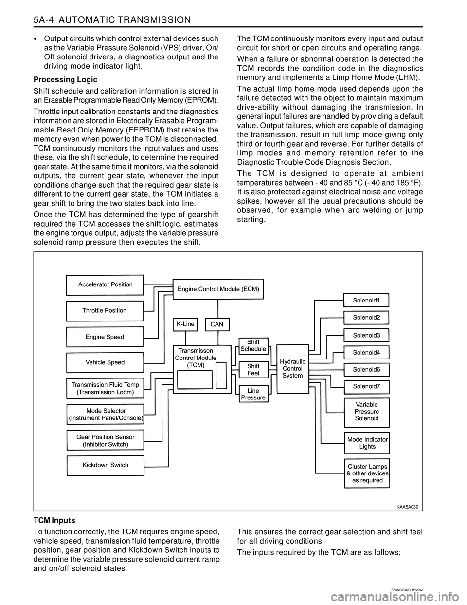
TCM Inputs
To function correctly, the TCM requires engine speed,
vehicle speed, transmission fluid temperature, throttle
position, gear position and Kickdown Switch inputs to
determine the variable pressure solenoid current ramp
and on/off solenoid states.
KAA5A030
This ensures the correct gear selection and shift feel
for all driving conditions.
The inputs required by the TCM are as follows;
Page 1099 of 2053
AUTOMATIC TRANSMISSION 5A-5
SSANGYONG MY2002
Engine Speed
The engine speed signal is derived from the Control-
ler Area Network (CAN) via Engine Control Module
(ECM).
Vehicle Speed
The vehicle speed sensor, which is located in the
transfer case, sends the output shaft speed signal
to the Engine Control Module (ECM). The information
is then transferred to the TCM via the CAN.
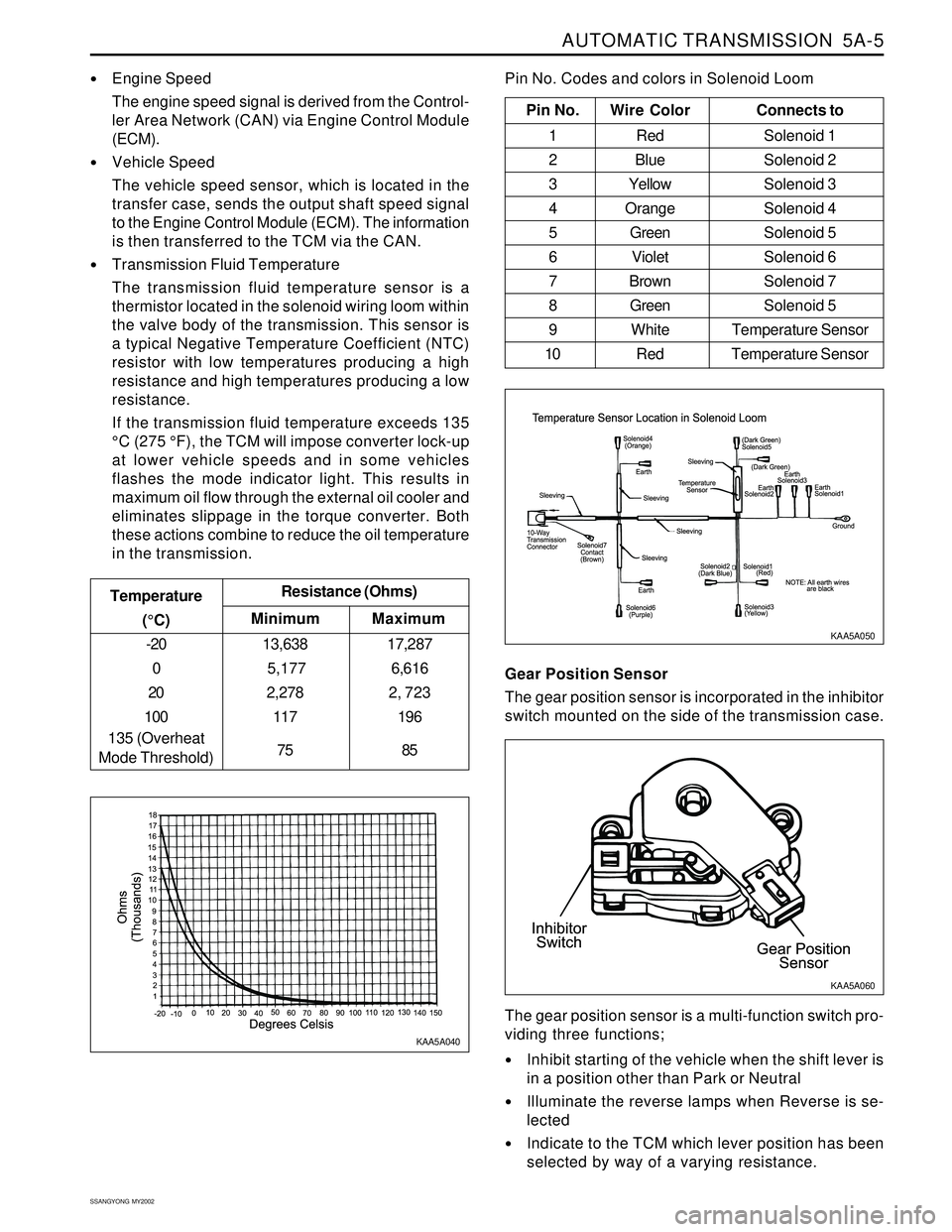
Transmission Fluid Temperature
The transmission fluid temperature sensor is a
thermistor located in the solenoid wiring loom within
the valve body of the transmission. This sensor is
a typical Negative Temperature Coefficient (NTC)
resistor with low temperatures producing a high
resistance and high temperatures producing a low
resistance.
If the transmission fluid temperature exceeds 135
°C (275 °F), the TCM will impose converter lock-up
at lower vehicle speeds and in some vehicles
flashes the mode indicator light. This results in
maximum oil flow through the external oil cooler and
eliminates slippage in the torque converter. Both
these actions combine to reduce the oil temperature
in the transmission.
Minimum Temperature
(°C)Resistance (Ohms)
-20
0
20
100
135 (Overheat
Mode Threshold)13,638
5,177
2,278
117
75
Maximum
17,287
6,616
2, 723
196
85
Pin No. Wire ColorConnects to
1 Red Solenoid 1
2 BlueSolenoid 2
3 YellowSolenoid 3
4 OrangeSolenoid 4
5 GreenSolenoid 5
6 VioletSolenoid 6
7 BrownSolenoid 7
8 GreenSolenoid 5
9 White Temperature Sensor
10 Red Temperature Sensor
Pin No. Codes and colors in Solenoid Loom
KAA5A040KAA5A050
Gear Position Sensor
The gear position sensor is incorporated in the inhibitor
switch mounted on the side of the transmission case.
Inhibit starting of the vehicle when the shift lever is
in a position other than Park or Neutral
Illuminate the reverse lamps when Reverse is se-
lected
Indicate to the TCM which lever position has been
selected by way of a varying resistance. The gear position sensor is a multi-function switch pro-
viding three functions;
KAA5A060
Page 1147 of 2053

5A-52 AUTOMATIC TRANSMISSION
SSANGYONG MY2002
Circuit Description
The Transmission Control Module (TCM) Diagnistic
System Check is the starting point for any driveability
complaint diagnosis. Before using this procedure,
perform a careful visual/physical check of the
Transmission Control Module (TCM) and the
transmission grounds for cleanliness and tightness.
The TCM Diagnostic System Check is an organized
approach to identifying a problem created by an
electronic transmission control system malfunction.
TCM DIAGNOSTIC SYSTEM CHECK
Diagnostic Aids
An intermittent fault may be caused by a poor connec-
tion, rubbed-through wire insulation or a wire broken
inside the insulation. Check for poor connections or a
damaged harness. Inspect the TCM harness and con-
nections for improper mating, broken locks, improperly
formed or damaged terminals, poor terminal-to-wire
connection, and damaged harness.
TCM Diagnostic System Check
1
StepAction Value(s) Yes No
21 Turn the ignition OFF.
2. Install the scan tool.
3. Turn the ignition ON, with the engine OFF.
4. Attempt to display the Transmission Control
Module (TCM) Data List with the scan tool.
Does the scan tool display the TCM data?
Select the Trouble Code with the scan tool.
Are any Diagnostic Trouble Codes (DTCs) stored?
- Go to Step 2 Go to Step 3
Go to
applicable
DTC table -System OK,
Check
Complete
KAA5A5KA
Page 1161 of 2053

5A-66 AUTOMATIC TRANSMISSION
SSANGYONG MY2002
Circuit Description
The driving mode selector switch is located on the
center console and allows the driver to select the
driving mode.
When NORMAL mode is selected upshifts will occur
to maximize fuel economy. When POWER mode is se-
lected, upshifts will occur to give maximum
performance and the POWER mode indicator light is
switched ON.
When WINTER mode is selected, starting in second
gear is facilitated, the WINTER mode indicator light is
switched ON and the POWER mode indicator light is
switched OFF.
The DTC P0790 sets when an intermittent connection
in the mode selector switch (mode switch) circuit has
been detected. The mode switch input is rapidly
changing states. The switching frequency is greater
than 8.3 Hz.
Conditions for Setting the DTC
The mode switching frequency is greater than 8.3
Hz.
The above condition must be continuously present
for 4 state changes.
Action Taken When the DTC Sets
All shifts will occur as if the mode is set to NORMAL.
The mode indicator will always be OFF indicating
that NORMAL mode is selected.
The mode indicator will not respond to the changes
in switch setting.
DIAGNOSTIC TROUBLE CODE (DTC) P0790
NORMAL/PERFORMANCE SWITCH CIRCUIT MALFUNCTION
Conditions for Clearing the DTC
The DTC will clear after 3 seconds without the fault.
A history DTC will clear after 40 TCM power-up
cycles with a warm transmission (>50 °C) and
without a fault.
History DTCs can be cleared by using a scan tool.
Diagnostic Aids
This fault is caused by too many changes in the
mode input signal over a period of time.
Typical causes would be an intermittent connection
in the switch or wiring or an intermittent short to
ground in the wiring.
Test Description
The number(s) below refer to the step number(s) on
the Diagnostic Table.
3. Check mode switch signal circuit for an
intermittent open / short
5. Check mode switch ground circuit for an
intermittent open / short
8. Check mode switch feed circuit for an intermittent
open / short
KAA5A5NA
Page 1357 of 2053
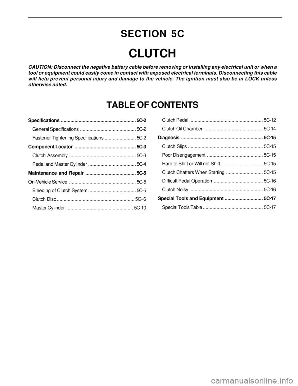
Specifications.......................................................5C-2
General Specifications.........................................5C-2
Fastener Tightening Specifications.......................5C-2
Component Locator.............................................5C-3
Clutch Assembly.................................................5C-3
Pedal and Master Cylinder...................................5C-4
Maintenance and Repair.....................................5C-5
On-Vehicle Service.................................................5C-5
Bleeding of Clutch System...................................5C-5
Clutch Disc......................................................... 5C- 6
Master Cylinder.................................................5C-10Clutch Pedal...................................................... 5C-12
Clutch Oil Chamber........................................... 5C-14
Diagnosis............................................................ 5C-15
Clutch Slips....................................................... 5C-15
Poor Disengagement ......................................... 5C-15
Hard to Shift or Will not Shift............................... 5C-15
Clutch Chatters When Starting........................... 5C-15
Difficult Pedal Operation.................................... 5C-16
Clutch Noisy...................................................... 5C-16
Special Tools and Equipment............................ 5C-17
Special Tools Table............................................ 5C-17
SECTION 5C
CLUTCH
CAUTION: Disconnect the negative battery cable before removing or installing any electrical unit or when a
tool or equipment could easily come in contact with exposed electrical terminals. Disconnecting this cable
will help prevent personal injury and damage to the vehicle. The ignition must also be in LOCK unless
otherwise noted.
TABLE OF CONTENTS
Page 1369 of 2053

CLUTCH 5C-15
SSANGYONG MY2002
Replace
Repair or Replace
Replace
Replace
Adjust
Repair or Replace
Replace Excessive Wear of Facing
Hard or Oily Facing
Damaged Pressure Plate or Flywheel
Damaged or Burnt Diaphragm Spring
Clutch Pedal Free play Insufficient
Faulty Operation of Clutch Pedal
Worn or Damaged Clutch DiscAction Checks
DIAGNOSIS
CLUTCH SLIPS
Replace
Repair or Replace
Repair or Replace
Replace
Adjust Vibration or Excessive Run-out of Disc
Rust or Wear of Disc Spline
Oily Facing
Damaged Diaphragm Spring
Excessive Clutch Pedal Free playAction Checks
POOR DISENGAGEMENT
Adjust Pedal Freeplay
Repair Release Cylinder
Repair or Replace
Repair as Necessary
Replace Excessive Clutch Pedal Free play
Faulty Clutch Release Cylinder
Worn Disc, Excessive Run-out, Damaged Lining
Dirty or Burred Splines on Input Shaft or Clutch Disc
Damaged Clutch Pressure PlateAction Checks
HARD TO SHIFT OR WILL NOT SHIFT
Repair or Replace
Replace
Replace
Replace
Replace
Repair or Replace
Tighten or Replace Oily Facing
Hard or Faulty Facing
Burnt Torsion Spring
Faulty Pressure Plate
Bent Clutch Diaphragm Spring
Hard or Bent Flywheel
Engine Mounts Loose or Burnt LeverAction Checks
CLUTCH CHATTERS WHEN STARTING