STARTING SSANGYONG KORANDO 1997 Service Owner's Guide
[x] Cancel search | Manufacturer: SSANGYONG, Model Year: 1997, Model line: KORANDO, Model: SSANGYONG KORANDO 1997Pages: 2053, PDF Size: 88.33 MB
Page 1592 of 2053

SUPPLEMENTAL RESTRAINTS SYSTEM 8B-7
SSANGYONG MY2002
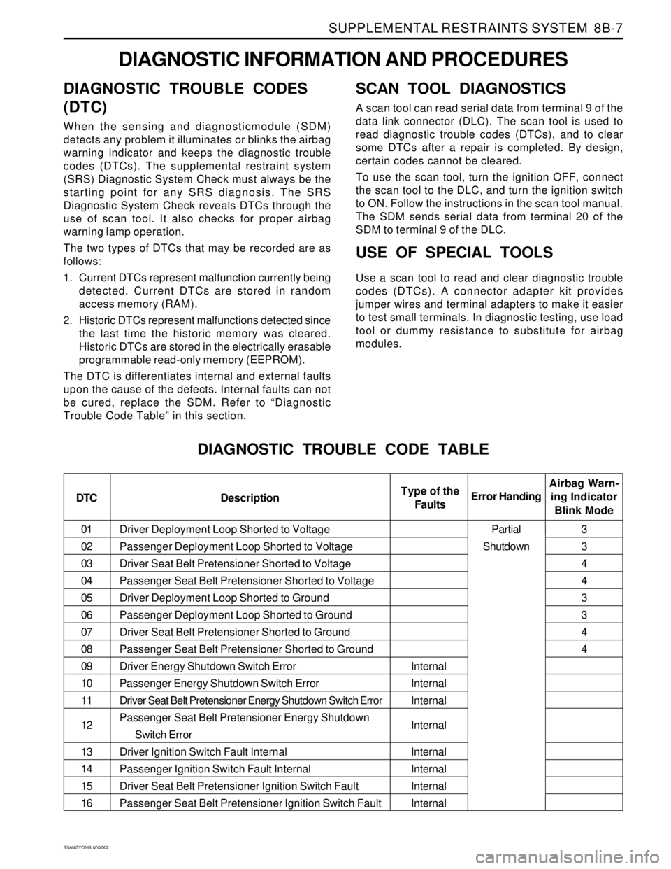
Driver Deployment Loop Shorted to Voltage
Passenger Deployment Loop Shorted to Voltage
Driver Seat Belt Pretensioner Shorted to Voltage
Passenger Seat Belt Pretensioner Shorted to Voltage
Driver Deployment Loop Shorted to Ground
Passenger Deployment Loop Shorted to Ground
Driver Seat Belt Pretensioner Shorted to Ground
Passenger Seat Belt Pretensioner Shorted to Ground
Driver Energy Shutdown Switch Error
Passenger Energy Shutdown Switch Error
Driver Seat Belt Pretensioner Energy Shutdown Switch Error
Passenger Seat Belt Pretensioner Energy Shutdown
Switch Error
Driver Ignition Switch Fault Internal
Passenger Ignition Switch Fault Internal
Driver Seat Belt Pretensioner Ignition Switch Fault
Passenger Seat Belt Pretensioner Ignition Switch Fault 01
02
03
04
05
06
07
08
09
10
11
12
13
14
15
16
DIAGNOSTIC INFORMATION AND PROCEDURES
DIAGNOSTIC TROUBLE CODES
(DTC)
When the sensing and diagnosticmodule (SDM)
detects any problem it illuminates or blinks the airbag
warning indicator and keeps the diagnostic trouble
codes (DTCs). The supplemental restraint system
(SRS) Diagnostic System Check must always be the
starting point for any SRS diagnosis. The SRS
Diagnostic System Check reveals DTCs through the
use of scan tool. It also checks for proper airbag
warning lamp operation.
The two types of DTCs that may be recorded are as
follows:
1. Current DTCs represent malfunction currently being
detected. Current DTCs are stored in random
access memory (RAM).
2. Historic DTCs represent malfunctions detected since
the last time the historic memory was cleared.
Historic DTCs are stored in the electrically erasable
programmable read-only memory (EEPROM).
The DTC is differentiates internal and external faults
upon the cause of the defects. Internal faults can not
be cured, replace the SDM. Refer to “Diagnostic
Trouble Code Table” in this section.
SCAN TOOL DIAGNOSTICS
A scan tool can read serial data from terminal 9 of the
data link connector (DLC). The scan tool is used to
read diagnostic trouble codes (DTCs), and to clear
some DTCs after a repair is completed. By design,
certain codes cannot be cleared.
To use the scan tool, turn the ignition OFF, connect
the scan tool to the DLC, and turn the ignition switch
to ON. Follow the instructions in the scan tool manual.
The SDM sends serial data from terminal 20 of the
SDM to terminal 9 of the DLC.
USE OF SPECIAL TOOLS
Use a scan tool to read and clear diagnostic trouble
codes (DTCs). A connector adapter kit provides
jumper wires and terminal adapters to make it easier
to test small terminals. In diagnostic testing, use load
tool or dummy resistance to substitute for airbag
modules.
DIAGNOSTIC TROUBLE CODE TABLE
DTC DescriptionAirbag Warn-
ing Indicator
Blink Mode Error HandingType of the
Faults
Internal
Internal
Internal
Internal
Internal
Internal
Internal
Internal3
3
4
4
3
3
4
4
Partial
Shutdown
Page 1595 of 2053

SSANGYONG MY2002
8B-10 SUPPLEMENTAL RESTRAINTS SYSTEM
SRS DIAGNOSTIC SYSTEM CHECK
Notice: If the vehicle interior has been exposed to
extensive water intrusion such as water leaks, driving
through high water, flooding, or other caucuses, the
sensing and diagnostic module (SDM) and SDM
connector may be need to be replaced. With ignition
OFF, inspect the area around the SDM, including the
carpet. If any significant soaking or evidence of previous
soaking is detected, the water must be removed, water
damage repaired, and the SDM and SDM connector must
be replaced. Before attempting any of these repairs, the
supplemental restraint system (SRS) must be disabled.
Refer to “Disabling the SRS” and “Sensing and
Diagnostic Module (SDM)” in this section.
The SRS Diagnostic System Check must always be
the starting point for any SRS system diagnosis. The
SRS Diagnostic System Check reveals diagnostic
trouble codes (DTCs) through the use of scan tool.
The diagnostic procedures used in this section are
designed to find and repair SRS conditions. To get
the best results, it is important to use the diagnostic
charts and follow the sequence listed below.
1. Perform the SRS Diagnostic System Check, which
reveals diagnostic trouble codes (DTCs) through
the use of scan tool. It also checks for proper airbag
indicator operation.
2. Refer to the proper diagnostic chart as directed by
SRS Diagnostic System Check. Bypassing these
procedures may result in extended diagnostic time,
incorrect diagnosis, and incorrect parts
replacement.3. Repeat the SRS Diagnostic System Check after any
repair or diagnostic procedures have been
performed to ensure that the repair has beenmade
correctly and that no other malfunction exists.
Circuit Description
When the ignitions witch is first turned to ON, ignition
voltage is supplied from airbag fuse to the SDM at
input terminal 5. The SDM responds by turning on the
airbag indicator for 4.5 seconds and then turning it off
while the SDM performs tests on the SRS system.
Diagnostic Aids
The order in which DTCs are diagnosed is very
important. Failure to diagnose the DTCs in the order
specified may result in extended diagnostic time,
incorrect diagnosis, and incorrect parts replacement.
Test Description
The numbers below refer to steps on the diagnostic
table.
2. This test differentiates between an indicator that
will not come on and an indicator that stays on when
it should be off.
3. Refer to the first caution below
5. This test, along with step 6, differentiates internal
or external faults of SDM.
9. Refer to the cautions below.
Page 1640 of 2053

SSANGYONG MY2002
8B-58 SUPPLEMENTAL RESTRAINTS SYSTEM
REPAIR INSTRUCTION
ON-VEHICLE SERVICE
SERVICE PRECAUTION
Caution: The sensing and diagnosis module (SDM)
can maintain sufficient voltage to deploy the airbags
and pretensioner for 0.15 seconds after the ignition
is OFF and the airbag fuse has been removed. If the
airbags or pretensioners are not disconnected, do
not begin service until one minute has passed after
disconnecting power to the SDM. If the airbag are
disconnected, service can begin immediately without
waiting for one-minute time period to expire. Failure
to temporarily disable the SRS during service can
result in unexpected deployment, personal injury,
and otherwise unneeded SRS repairs.
DISABLING THE SUPPLEMENTAL
RESTRAINT SYSTEM (SRS)
1. Turn the steering wheel to the straight-ahead
position.
2. Turn the ignition switch to LOCK and remove the key.
3. Remove the airbag fuse F31 in the I/P fuse block
and wait more than one minute for SRS capacitor to
discharge.
ENABLING THE SUPPLEMENTAL
RESTRAINT SYSTEM (SRS)
Enabling the supplemental restraint system (SRS) is
reverse order of “Disabling the Supplemental Restraint
System (SRS)”.
Caution: Staying well away from the inflator
modules, turn the ignition key switch to ON, and
verify that the airbag indicator illuminates for 4.5
seconds and turns OFF. If it does not operate as
described, perform the “SRS Diagnostic System
Check” referring in this section.
HANDLING, INSTALLATION AND
DIAGNOSIS
Airbag modules should not be subjected to
temperature above 65°C (149°F)
An airbag module or sensing and diagnostic module
(SDM) should not be used if it has been dropped
from height of 0.9 meters (3 feet) or greater.
It is very important for the SDM to be installed flat
on the mounting surface, parallel to the vehicle’s
longitudinal axis.
To avoid setting diagnostic trouble codes (DTCs),
do not apply power to the SRS unless all components
are connected or a diagnostic chart request it.
The SRS Diagnostic System Check must be the
starting point of any SRS diagnostics. The SRS
Diagnostic System Check will verify proper airbag
indicator operation and will lead you to correct chart
to diagnose any SRS malfunctions. Bypassing
these procedures may result in extended diagnostic
time and incorrect parts replacements.
REPAIRS AND INSPECTIONS
REQUIRED AFTER AN ACCIDENT
Caution: any repairs to the vehicle’s structure must
return it to the original production configuration.
Deployment requires replacement of SDM, the
inflator modules, and a dimensional inspection of
the steering column.
If any SRS components are damaged, they must
be replaced. If SRS components mounting points
are damaged, they must be repaired or replaced.
Never use SRS parts from another vehicle. This does
not include remanufactured parts purchased from
an authorized source.
Do not attempt to service the SDM, the clock spring,
or other airbag modules, these items must be
replaced if they are defective.
Verify the part number of replacement airbag
modules. Some inflator modules look identical but
contain different internal components.
ACCIDENT WITH DEPLOYMENT -
COMPONENTS REPLACEMENT
All SRS components must be replaced after frontal crash
involving airbag deployment. After deployment, a
powdery residue may be on the surface of the airbag.
The powder consists primarily of cornstarch (used to
lubricate the bag as it inflates) and by-products of the
chemical reaction. Sodium hydroxide dust (similar to
lye soap) is produced as a by-product of the deployment
reaction. The sodium hydroxide then quickly reacts with
atmospheric moisture and is converted to sodium
carbonate and sodium bicarbonate (also known as
baking soda). Therefore, it is unlikely that sodium
hydroxide will be present after deployment. Replace
the following SRS components.
Caution: Wear gloves and safety glasses during the
disposal procedure. Refer to “Deployed Airbag
Module Disposal Procedure” in this section.
The SDM.
Airbag modules and pretensioners
SRS wiring
Clock spring
Page 1658 of 2053

BODY WIRING SYSTEM 9A-7
SSANGYONG MY2002
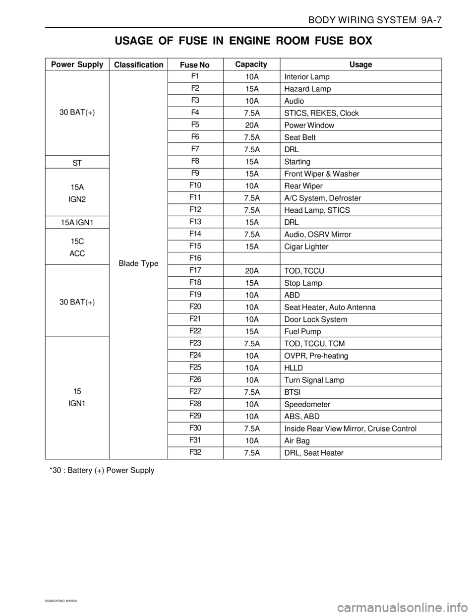
USAGE OF FUSE IN ENGINE ROOM FUSE BOX
Interior Lamp
Hazard Lamp
Audio
STICS, REKES, Clock
Power Window
Seat Belt
DRL
Starting
Front Wiper & Washer
Rear Wiper
A/C System, Defroster
Head Lamp, STICS
DRL
Audio, OSRV Mirror
Cigar Lighter
TOD, TCCU
Stop Lamp
ABD
Seat Heater, Auto Antenna
Door Lock System
Fuel Pump
TOD, TCCU, TCM
OVPR, Pre-heating
HLLD
Turn Signal Lamp
BTSI
Speedometer
ABS, ABD
Inside Rear View Mirror, Cruise Control
Air Bag
DRL, Seat Heater Power SupplyUsage
Classification
Fuse NoCapacity
30 BAT(+)
ST
15A
IGN2
15A IGN1
15C
ACC
30 BAT(+)
15
IGN1
Blade TypeF1
F2
F3
F4
F5
F6
F7
F8
F9
F10
F11
F12
F13
F14
F15
F16
F17
F18
F19
F20
F21
F22
F23
F24
F25
F26
F27
F28
F29
F30
F31
F3210A
15A
10A
7.5A
20A
7.5A
7.5A
15A
15A
10A
7.5A
7.5A
15A
7.5A
15A
20A
15A
10A
10A
10A
15A
7.5A
10A
10A
10A
7.5A
10A
10A
7.5A
10A
7.5A
*30 : Battery (+) Power Supply
Page 1662 of 2053

BODY WIRING SYSTEM 9A-11
SSANGYONG MY2002
WIRING HARNESS & CONNECTOR & GROUND LOCATION
W/H ENGINE ROOM
KAA9A070
1 Starting motor
2 G102
3 Damper solenoid (FRT LH)
4 Compressor
5 Wheel speed sensor (FRT LH)
6 Starting motor “ST” terminal connector
7 Canister purge valve (Gasoline E/G)
8 Pre-heating time control unit (Diesel E/G)
9 C109 (Diesel E/G)
10 J102
11 J101
12 G101
13 Turn signal & position lamp (FRT LH)
14 Fog lamp (FRT LH)
15 Head lamp (FRT LH)
16 HLLD (FRT LH)
17 Hood switch
18 Thermo switch (Diesel E/G)
19 LH horn
20 Condenser fan motor-Non A/conditioner
21 Condenser fan motor (LH)22 Resistor
23 RH horn
24 Fog lamp (FRT RH)
25 Condenser fan motor (RH)
26 Head lamp (FRT RH)
27 HLLD (FRT RH)
28 Turn signal & position lamp (FRT RH)
29 G103
30 C110 (Diesel E/G)
31 Alternator B+ (Diesel E/G)
32 J104
33 J103
34 C110 (Gasoline E/G)
35 Alternator B+ (Gasoline E/G)
36 Damper Solenoid (FRT RH)
37 C111
38 Wheel speed sensor (FRT RH)
39 Dual pressure switch
40 Washer motor
41 ADD (FRT RH)
42 C112
43 C113
Page 1719 of 2053

SSANGYONG MY2002
9E-2 INSTRUMENTATION, DRIVER INFORMATION
DESCRIPTION AND OPERATION
CIGAR LIGHTER
The cigar lighter is located in the front portion of the
floor console. To use the lighter, push it in completely.
When the lighter is hot, it will release itsef from contact
with the heating element. The lighter and the heating
element can be damaged if the lighter does not fully
release itsef from the heating element.
ASHTRAY
The ashtray is located in the console. To access the
ashtray, pullit out of the ashtray housing. The ashtray
lamp will go on when the parking lamps or headlamps
are turned on.
INSTRUMENT PANEL VENTS
The center and the side vents in the instrument panel
can be adjusted up and down and from side to side.
The side vents can also be aimed toward the side
windows to defog them.
GLOVE BOX
The glove box can be opened by pulling upon the latch
handle.
DIGITAL CLOCK
The digital clock is located in the instrument cluster.
INSTRUMENT CLUSTER
The instrument cluster is located above the steering
column and in the instrument cluster trim panel. The
instrument cluster contains the instruments that
provide the driver with vehicle performance information.
The instrument cluster contains a speedometer, a
tachometer, an odometer, a trip odometer, a
temperature gauge, a fuel gauge, and several indicator
lamps. For replacement of the indicator lamp bulbs
contained in the instrument cluster, refer to “Instrument
Cluster Indicator Lamps Specifications” in the section.
SPEEDOMETER AND
TACHOMETER
The speedometer measures the speed of the vehicle
in km/h (with mph) or mph (with km/h). It consists of
an instrument cluster gauge connected to the vehicle
speed sensor on the transaxle output shaft. The
tachometer measures the engine’s speed in terms of
thousands of revolutions per minute. It consists of an
instrument cluster gauge connected to a sending unit
in the engine con-trol module. Do not operate the
engine in the red zone. Engine damage may occur.
TRIP ODOMETER
The trip odometer measures the distance the vehicle
has traveled since it was last reset. It consists of an
instrument cluster gauge connected to the sending unit
on the tasnsaxle output shaft. The trip oddometer can
be record the distance traveled from any starting point.
FUEL GAUGE
The fuel gauge consists of an instrument cluster gauge
connected to a sending unit in the fuel tank. The fuel
gauge indicates the quantity of fuel in the tank only
when the ignition is turned to ON or ACC. When the
ignition is turned to LOCK or START, the pointer may
come to rest at any position.
TEMPERATURE GAUGE
The temperature gauge consists of an instrument
cluster gauge connected to a temperature sensor that
is in con-tact with the circulating engine coolant. The
temperature gauge indicates the temperature of the
coolant. Prolonged driving or idling in very hot weather
may cause the pointer to move beyond the center of
the gauge. The engine is overheating if the pointer
moves into the red zone at the upper limit of the gauge.
INSTRUMENT CLUSTER
INDICATOR LAMPS
The instrument cluster contains indicator lamps that
indicatethe functioning of certain systems or the
existenceof potential problems with the operation of
the vehicle. The indicator lamps are replaceable. For
replacement of the indicator lamps contained in the
instrument cluster, refer to “instrument cluster indicator
lamps specifications” in this section.
CHIME MODULE
The chime module will sound to bring attention to one
or more of the following conditions:
The lights are on and the ignition not in ACC, ON,
or START.
The ignition key is in the ignition switch when the
driver’s side door is open.
The seat belt is unbuckled when the ignition is in
ACC, ON, or START.
Voltage is supplied at all times through the fuse block
to power the chime module.
Page 1852 of 2053

REMOTE KEYLESS ENTRY AND ANTI-THEFT SYSTEM 9T1-5
SSANGYONG MY2002
KAA9T020
KAA9T030
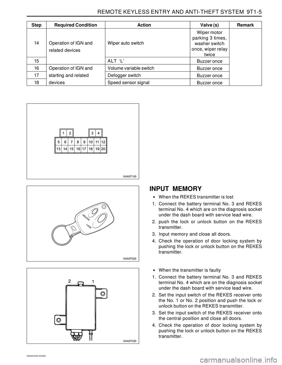
INPUT MEMORY
When the REKES transmitter is lost
1. Connect the battery terminal No. 3 and REKES
terminal No. 4 which are on the diagnosis socket
under the dash board with service lead wire.
2. push the lock or unlock button on the REKES
transmitter.
3. Input memory and close all doors.
4. Check the operation of door locking system by
pushing the lock or unlock button on the REKES
transmitter.
When the transmitter is faulty
1. Connect the battery terminal No. 3 and REKES
terminal No. 4 which are on the diagnosis socket
under the dash board with service lead wire.
2. Set the input switch of the REKES receiver onto
the No. 1 or No. 2 position and push the lock or
unlock button on the REKES transmitter.
3. Set the input switch of the REKES receiver onto
the central position and close all doors.
4. Check the operation of door locking system by
pushing the lock or unlock button on the REKES
transmitter.
Step Required ConditionActionRemark Valve (s)
Wiper motor
parking 3 times,
washer switch
once, wiper relay
twice
Buzzer once
Buzzer once
Buzzer once
Buzzer once Wiper auto switch
ALT ‘L’
Volume variable switch
Defogger switch
Speed sensor signal
Operation of IGN and
related devices
Operation of IGN and
starting and related
devices14
15
16
17
18
KAA9T100
Page 1858 of 2053

SSANGYONG MY2002
9T2-2 IMMOBILIZER SYSTEM
DESCRIPTION AND OPERATION
Immobilizer is a device disabling vehicle ignition unless
a speific key is used and designed to help prevent
vehicle theft.
Immobilizer is comprised of two devices, a key with
encoded transponder and engine control unit (ECU)
with the same encoding of the transponder. When a
key is inserted into the key hole to start vehicle and
turned to ‘ON’, the ECU reads and decodes the
transponder code and, if the same, starts the engine,
it is called immobilizer. It means immobilizer system
disables starting by stopping fuel supply if the code
in the transponder does not match the code stored in
ECU each other.
Notice:
If vehicle is equipped with immobilizer system and
the engine cranks normally but not start, check
immobilizer system first rather than ignition and
other electrical systems because it can be
disabled fuel supply of injectors by ECU due to
defective immobilizer system.
Programming of the immobilizer system will be
performed by authorized personnel only. If
following defective codes for immobilizer system
appear during diagnosis of vehicle with SCANNER,
ask immobilizer programming to authorized
personnel and actual programming should be
performed by authorized per-sonnel only.
Display of defectives relevant to immobilizer
system : SCANNER
1. No communication with transponder
2. No immobilizer programming
The transponder in the key can be damaged by
shocks of dropping or hitting other objectives, so
handle it with care.
Each supplied key has programming of code on
its own. Accordingly if ECU needs to be replaced,
replace the transponder in the key.
The vehicle equipped with immobilizer system will
never be started with remote ignition device, so
do not attempt to install it.
The immobilizer system will never be removed from
the vehicle. So never attempt to remove it to install
a remote ignition device or others.
If engine does not start during service, use every
key to start the engine and then check immobilizer
sys-tem finally.
Cases that requires immobilizer
programming
1. Replacement ECU
In this case, replace the every transponder of the
key at once.
2. Replacement of the transponder
3. Additional key for lost 1 or 2 keys
1) Clear all codes for current keys from the ECU
2) When using current key : clear code of the trans-
ponder and re-program it
3) Additional (purchased) key : perform programming
4. When lost all keys
1) Clear all memorized key codes from the ECU
2) Replace the key and key set
3) Immobilizer programming
Page 1870 of 2053

2-6 2-6 2-6 2-6
2-6
ELECTRICAL WIRING DIAGRAMS ELECTRICAL WIRING DIAGRAMSELECTRICAL WIRING DIAGRAMS ELECTRICAL WIRING DIAGRAMS
ELECTRICAL WIRING DIAGRAMS3. 3.3. 3.
3.
WIRING HARNESS & CONNECT WIRING HARNESS & CONNECTWIRING HARNESS & CONNECT WIRING HARNESS & CONNECT
WIRING HARNESS & CONNECT
OR & GR OR & GROR & GR OR & GR
OR & GR
OUND LOCA OUND LOCAOUND LOCA OUND LOCA
OUND LOCA
TION TIONTION TION
TION1) 1)1) 1)
1)
W/H ENGINE ROOM W/H ENGINE ROOMW/H ENGINE ROOM W/H ENGINE ROOM
W/H ENGINE ROOM
1. Starting motor
2. G102
3. -
4. Compressor
5. Wheel speed sensor(FRT LH)
6. Starting motor "ST" terminal connector
7. Canister purge valve (Gasoline E/G)
8. Pre-heating time control unit (Diesel E/G)
9. C109 (Diesel E/G)
10. J102
11. J101
12. G101
13. Turn signal & position lamp(FRT LH)
14. Fog lamp(FRT LH)
15. Head lamp(FRT LH)
16. HLLD (FRT LH)
17. Hood switch
18. Thermo switch (Diesel E/G)
19. LH horn
20. Condenser fan motor-Non A/conditioner
21. Condenser fan motor(LH)
22. Resistor
23. RH horn
24. Fog lamp(FRT RH)
25. Condenser fan motor(RH)
26. Head lamp(FRT RH)
27. HLLD (FRT RH)
28. Turn signal & position lamp(FRT RH)
29. G103
30. C110 (Diesel E/G)
31. Alternator B+ (Diesel E/G)
32. J104
33. J103
34. C110 (Gasoline E/G)
35. Alternator B+ (Gasoline E/G)
36. -
37. C111
38. Wheel speed sensor(FRT RH)
39. Dual pressure switch
40. Washer motor
41. ADD (FRT RH)
42. C112
43. C113
FUSE &RELAY BOX
42
43
41
40
393435
37303138
2928
25
26
24
23
2221201918
17
1516
13
12111089
7
6
5
4321
14
27
3233
Page 1893 of 2053

USAGE AND CAPACITY OF FUSES IN FUSE BOX USAGE AND CAPACITY OF FUSES IN FUSE BOX USAGE AND CAPACITY OF FUSES IN FUSE BOX USAGE AND CAPACITY OF FUSES IN FUSE BOX
USAGE AND CAPACITY OF FUSES IN FUSE BOX
4-3 4-34-3 4-3
4-3
2. 2.2. 2.
2.
PASSENGER ROOM FUSE BOX PASSENGER ROOM FUSE BOXPASSENGER ROOM FUSE BOX PASSENGER ROOM FUSE BOX
PASSENGER ROOM FUSE BOX1) 1)1) 1)
1)
POSITION OF FUSE POSITION OF FUSEPOSITION OF FUSE POSITION OF FUSE
POSITION OF FUSE
2) 2)2) 2)
2)
USAGE OF FUSE IN PASSENGER ROOM FUSE BOX USAGE OF FUSE IN PASSENGER ROOM FUSE BOXUSAGE OF FUSE IN PASSENGER ROOM FUSE BOX USAGE OF FUSE IN PASSENGER ROOM FUSE BOX
USAGE OF FUSE IN PASSENGER ROOM FUSE BOX
10A
15A
15A
7.5A
30A
7.5A
-
15A
15A
10A
7.5A
7.5A
-
7.5A
15A
20A
15A
10A
10A
10A
15A
7.5A
10A
7.5A
10A
7.5A
10A
15A
7.5A
10A
7.5A F1
F2
F3
F4
F5
F6
F7
F8
F9
F10
F11
F12
F13
F14
F15
F16
F17
F18
F19
F20
F21
F22
F23
F24
F25
F26
F27
F28
F29
F30
F31
F32
Power Supply Power SupplyPower Supply Power Supply
Power Supply
Classification ClassificationClassification Classification
Classification
Fuse No Fuse NoFuse No Fuse No
Fuse No
Capacity CapacityCapacity Capacity
Capacity
Usage UsageUsage Usage
Usage* 30 : BAT(+) Power Supply Through Ef1.
Blade TypeInterior Lamp, Rr Fog Lp, Cluster
Hazard Lamp
Audio
STICS,REKES,Clock
Power Window
Seat Belt, Diagnosis(DLC)
-
Starting
Front Wiper & Washer
Rear Wiper
A/C System,Defroster
Head Lamp,STICS
-
Audio,OSRV Mirror
Cigar Lighter
TOD,TCCU
Stop Lamp
ABD
Seat Heater,Auto Antenna
Door Lock System
Fuel Pump
TOD,TCCU,TCM
OVPR,EGR
HLLD, B/UP Lamp
Turn Signal Lamp
BTSI, Pre-heating, Shift Lock
Speedometer
ABS,ABD
Inside Rear View Mirror, Cruise Control,
Immobilizer, Cluster
Air Bag
Seat Heater
30 BAT(+)
ST
15A
IGN2
30 BAT(+)15C
ACC 15A IGN1
15
IGN1