power steering fluid SSANGYONG KORANDO 1997 Service Owner's Manual
[x] Cancel search | Manufacturer: SSANGYONG, Model Year: 1997, Model line: KORANDO, Model: SSANGYONG KORANDO 1997Pages: 2053, PDF Size: 88.33 MB
Page 1456 of 2053
POWER STEERING SYSTEM 6A-5
SSANGYONG MY2002
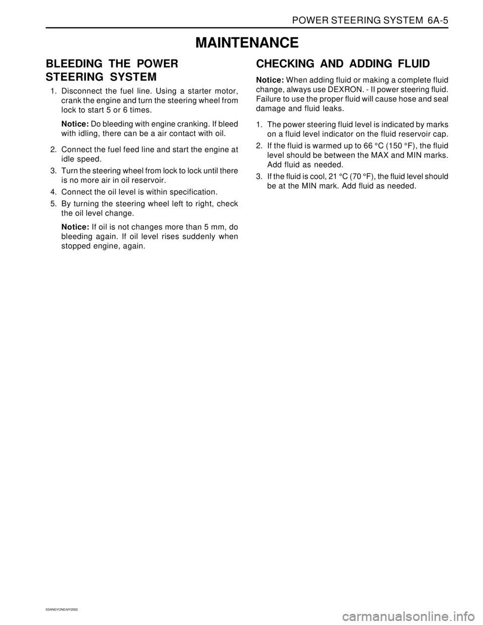
BLEEDING THE POWER
STEERING SYSTEM
1. Disconnect the fuel line. Using a starter motor,
crank the engine and turn the steering wheel from
lock to start 5 or 6 times.
Notice: Do bleeding with engine cranking. If bleed
with idling, there can be a air contact with oil.
2. Connect the fuel feed line and start the engine at
idle speed.
3. Turn the steering wheel from lock to lock until there
is no more air in oil reservoir.
4. Connect the oil level is within specification.
5. By turning the steering wheel left to right, check
the oil level change.
Notice: If oil is not changes more than 5 mm, do
bleeding again. If oil level rises suddenly when
stopped engine, again.
MAINTENANCE
CHECKING AND ADDING FLUID
Notice: When adding fluid or making a complete fluid
change, always use DEXRON. - II power steering fluid.
Failure to use the proper fluid will cause hose and seal
damage and fluid leaks.
1. The power steering fluid level is indicated by marks
on a fluid level indicator on the fluid reservoir cap.
2. If the fluid is warmed up to 66 °C (150 °F), the fluid
level should be between the MAX and MIN marks.
Add fluid as needed.
3. If the fluid is cool, 21 °C (70 °F), the fluid level should
be at the MIN mark. Add fluid as needed.
Page 1457 of 2053

SSANGYONG MY2002
6A-6 POWER STEERING SYSTEM
KAA6A040
3. Remove the power steering fluid reservoir
mounting bolts (1).
Removal Notice:
One power steering fluid reservoir mounting bolt
(2) is located in the fluid reservoir.
Installation Notice
KAA6A030
ON-VEHICLE SERVICE
POWER STEERING FLUID
RESERVOIR
Tools Required
DW310-021Power Steering Pump Pulley Remover/
Installer
Removal and Installation Procedure
1. Remove the power steering pump. Refer to
Section 6B, Power Steering Pump.
2. Remove the power steering pump pulley nut, using
the power steering pump pulley remover/installer
DW310-021.
Installation Notice
REPAIR INSTRUCTIONS
Tightening Torque 61 Nm (44 lb-ft)
15 Nm (11 lb-ft)
18 Nm (13 lb-ft)
Tightening
TorqueBolts (1)
Bolt (2)
4. Remove the power steering fluid reservoir upward.
After installing the power steering fluid reservoir,
bleed the power steering system. Refer to
“Bleeding the Power Steering System” in this
section.
5. Installation should follow the removal procedure
in the reverse order.
Page 1458 of 2053

POWER STEERING SYSTEM 6A-7
SSANGYONG MY2002
KAA6A050
KAA6A060
4. Disconnect the return line pipe from the power
steering gear outlet.
Installation Notice
KAA6A070
5. Disconnect the pressure line pipe from the power
steering gear inlet.
Installation Notice
POWER STEERING PUMP HOSES
AND PIPES
Removal and Installation Procedure
1. Remove the battery. Refer to Section 1E, Engine
Electrical.
2. Siphon the power steering fluid from the fluid reser-
voir.
3. Disconnect the pressure line pipe from the outlet
connection on the power steering pump and return
hose from the inlet connection on the power
steering fluid reservoir.
Installation Notice
Tightening Torque 44 Nm (33 lb-ft)
Tightening Torque 17 Nm (13 lb-ft)
Tightening Torque 17 Nm (13 lb-ft)
Page 1459 of 2053

SSANGYONG MY2002
6A-8 POWER STEERING SYSTEM
KAA6A080
6. Remove the return line support clip from the front
frame.
Installation Notice
Tightening Torque 9 Nm (80 lb-in)
After installing the power steering fluid reservoir,
bleed the power steering system. Refer to
“Bleeding the Power Steering System” in this
section.
7. Installation should follow the removal procedure
in the reverse order.
Page 1460 of 2053
POWER STEERING SYSTEM 6A-9
SSANGYONG MY2002
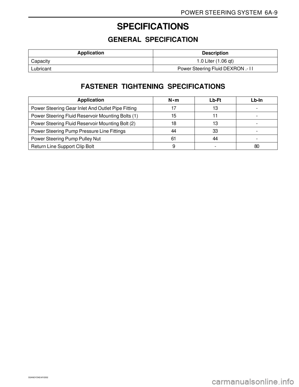
SPECIFICATIONS
GENERAL SPECIFICATION
N•m
17
15
18
44
61
9Lb-Ft
13
11
13
33
44
- Power Steering Gear Inlet And Outlet Pipe Fitting
Power Steering Fluid Reservoir Mounting Bolts (1)
Power Steering Fluid Reservoir Mounting Bolt (2)
Power Steering Pump Pressure Line Fittings
Power Steering Pump Pulley Nut
Return Line Support Clip BoltLb-In
-
-
-
-
-
80Application
Description
1.0 Liter (1.06 qt)
Power Steering Fluid DEXRON .- I I Capacity
LubricantApplication
FASTENER TIGHTENING SPECIFICATIONS
Page 1464 of 2053
POWER STEERING PUMP 6B-3
SSANGYONG MY2002
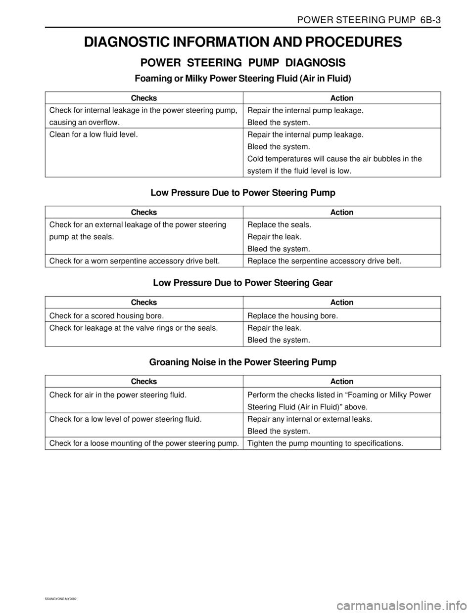
DIAGNOSTIC INFORMATION AND PROCEDURES
POWER STEERING PUMP DIAGNOSIS
Foaming or Milky Power Steering Fluid (Air in Fluid)
Low Pressure Due to Power Steering Pump
Check for a scored housing bore.
Check for leakage at the valve rings or the seals.ChecksActionReplace the housing bore.
Repair the leak.
Bleed the system.
Low Pressure Due to Power Steering Gear
Check for internal leakage in the power steering pump,
causing an overflow.
Clean for a low fluid level.ChecksActionRepair the internal pump leakage.
Bleed the system.
Repair the internal pump leakage.
Bleed the system.
Cold temperatures will cause the air bubbles in the
system if the fluid level is low.
Check for an external leakage of the power steering
pump at the seals.
Check for a worn serpentine accessory drive belt.ChecksActionReplace the seals.
Repair the leak.
Bleed the system.
Replace the serpentine accessory drive belt.
Check for air in the power steering fluid.
Check for a low level of power steering fluid.
Check for a loose mounting of the power steering pump.ChecksActionPerform the checks listed in “Foaming or Milky Power
Steering Fluid (Air in Fluid)” above.
Repair any internal or external leaks.
Bleed the system.
Tighten the pump mounting to specifications.
Groaning Noise in the Power Steering Pump
Page 1466 of 2053

POWER STEERING PUMP 6B-5
SSANGYONG MY2002
KAA6B050
5. Remove the power steering pump assembly
mounting bolts.
Installation Notice
KAA6B040
3. Siphon the power steering fluid from the fluid reser-
voir.
4. Disconnect the pressure line pipe from the outlet
connectionon the power steering pump and return
hose from the inlet connection on the power
steering fluid reservoir.
Installation Notice
Tightening Torque 44 Nm (33 lb-ft)
KAA6B010
POWER STEERING PUMP
ASSEMBLY
Removal and Installation Procedure
1. Remove the battery. Refer to Section 1E, Engine
Electrical.
2. Use a wrench to turn the tensioner bolt clockwise,
compressing the tensioner, and releasing the
tension on the serpentine accessory drive belt.
Loosen the serpentine accessory drive belt.
Tightening Torque 25 Nm (17 lb-ft)
6. Remove the power steering pump assembly.
Page 1467 of 2053

SSANGYONG MY2002
6B-6 POWER STEERING PUMP
KAA6B060
KAA6B070
3. Remove the power steering fluid reservoir
mounting bolts (1).
Remove Notice:
One power steering fluid reservoir mounting bolt
(2) is located in the fluid reservoir.
Installation Notice
KAA6B080
5. Remove the power steering pump mounting
bracket bolts.
Installation Notice
UNIT REPAIR
PUMP
Tools Required
DW310-021Power Steering Pump Pulley Remover/
Installer
Disassembly and Assembly Procedure
Important: The power steering pump in this vehicle is
not serviceable. Replace, do not repair, a faulty power
steering pump. Refer to “Power Steering Pump
Diagnosis” in this section.
1. Remove the power steering pump assembly. Refer
to “Power Steering Pump Assembly” in this
section.
2. Remove the power steering pump pulley nut, using
the power steering pump pulley remover/installer
DW 310-021.
Tightening Torque 16 Nm (12 lb-ft)15 Nm (11 lb-ft)
18 Nm (13 lb-ft)
Tightening
TorqueBolts (1)
Bolt (2)
4. Remover the power steering fluid reservoir
upward.
6. Installation should follow the removal procedure
in the reverse order.
Page 1468 of 2053
POWER STEERING PUMP 6B-7
SSANGYONG MY2002
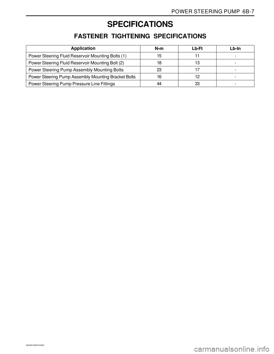
SPECIFICATIONS
FASTENER TIGHTENING SPECIFICATIONS
N•m
15
18
23
16
44Lb-Ft
11
13
17
12
33 Power Steering Fluid Reservoir Mounting Bolts (1)
Power Steering Fluid Reservoir Mounting Bolt (2)
Power Steering Pump Assembly Mounting Bolts
Power Steering Pump Assembly Mounting Bracket Bolts
Power Steering Pump Pressure Line FittingsLb-In
-
-
-
-
-Application
Page 1470 of 2053
SSANGYONG MY2002
6C-2 POWER STEERING GEAR
POWER RACK AND PINION
The power steering rack and pinion system has a rotary
control valve that directs hydraulic fluid coming from
the hydraulic pump to one side or the other side of the
rack piston. The integral rack piston is attached to the
rack. The rack piston converts hydraulic pressure to a
linear force that moves the rack left or right. That force
is then transmitted through the tie rods to the steering
knuckles, which turn the wheels.
DESCRIPTION AND OPERATION
If power rack and pinion steering is not available, manu-
al rack and pinion control is used; however, with this
system, more steering effort is required. The movement
of the steering wheel is transferred to the pinion. The
rotary movement of the pinion is then transferred
through the pinion threads, which mesh with teeth on
the rack, thereby causing the rack to move in a linear
direction.
A vane-type of hydraulic pump provides hydraulic pres-
sure for both steering systems.