torque SSANGYONG KORANDO 1997 Service Repair Manual
[x] Cancel search | Manufacturer: SSANGYONG, Model Year: 1997, Model line: KORANDO, Model: SSANGYONG KORANDO 1997Pages: 2053, PDF Size: 88.33 MB
Page 2 of 2053
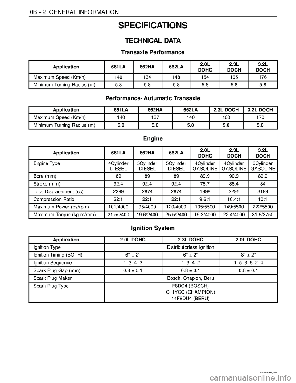
0B -- 2 GENERAL INFORMATION
D AEW OO M Y_2000
SPECIFICATIONS
TECHNICAL DATA
Transaxle Performance
Application661LA662NA662LA2.0L
DOHC2.3L
DOCH3.2L
DOCH
Maximum Speed (Km/h)140134148154165176
Minimum Turning Radius (m)5.85.85.85.85.85.8
Performance- Autumatic Transaxle
Application661LA662NA662LA2.3L DOCH3.2L DOCH
Maximum Speed (Km/h)140137140160170
Minimum Turning Radius (m)5.85.85.85.85.8
Engine
Application661LA662NA662LA2.0L
DOHC2.3L
DOCH3.2L
DOCH
Engine Type4Cylinder
DIESEL5Cylinder
DIESEL5Cylinder
DIESEL4Cylinder
GASOLINE4Cylinder
GASOLINE6Cylinder
GASOLINE
Bore (mm)89898989.990.989.9
Stroke (mm)92.492.492.478.788.484
Total Displacement (cc)229928742874199822953199
Compression Ratio22:122:122:19.6:110.4:110:1
Maximum Power (ps/rpm)101/400095/4000120/4000135/5500149/5500222/5500
Maximum Torque (kg.m/rpm)21.5/240019.6/240025.5/240019.3/400022.4/400031.6/3750
Ignition System
Application2.0L DOHC2.3L DOHC2.0L DOHC
Ignition TypeDistributorless Ignition
Ignition Timing (BOTH)6°±2°6°±2°8°±2°
Ignition Sequence1--3--4--21--3--4--21--5--3--6--2--4
Spark Plug Gap (mm)0.8±0.10.8±0.10.8±0.1
Spark Plug MakerBosch, Chapion, Beru
Spark Plug TypeF8DC4 (BOSCH)
C11YCC (CHAMPION)
14F8DU4 (BERU)
Page 7 of 2053
GENERAL INFORMATION 0B -- 7
D AEW OO M Y_2000
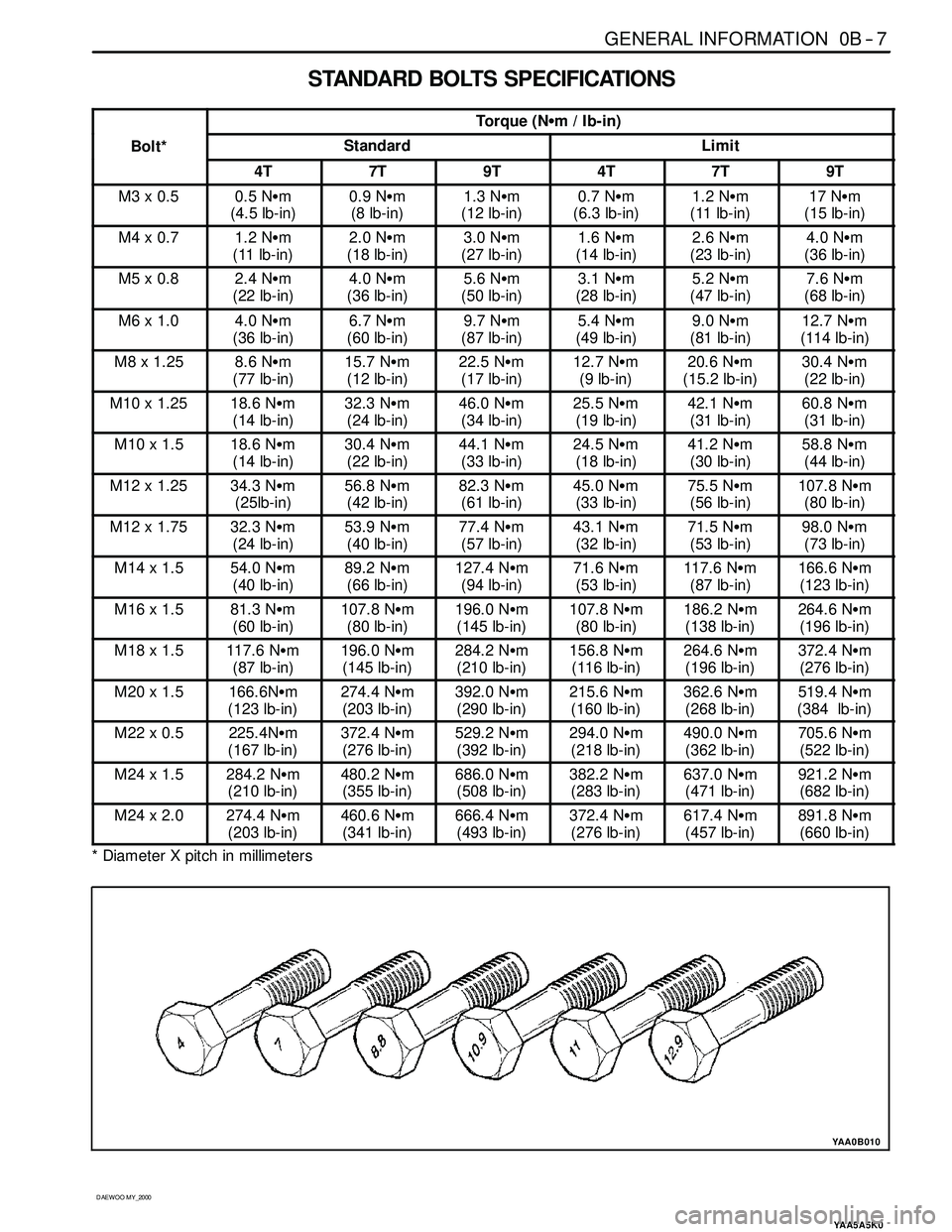
STANDARD BOLTSSPECIFICATIONS
Torque (NSm/Ib-in)
Bolt*StandardLimit
4T7T9T4T7T9T
M3 x 0.50.5 NSm
(4.5 lb-in)0.9 NSm
(8 lb-in)1.3 NSm
(12 lb-in)0.7 NSm
(6.3 lb-in)1.2 NSm
(11 lb-in)17 NSm
(15 lb-in)
M4 x 0.71.2 NSm
(11 lb-in)2.0 NSm
(18 lb-in)3.0 NSm
(27 lb-in)1.6 NSm
(14 lb-in)2.6 NSm
(23 lb-in)4.0 NSm
(36 lb-in)
M5 x 0.82.4 NSm
(22 lb-in)4.0 NSm
(36 lb-in)5.6 NSm
(50 lb-in)3.1 NSm
(28 lb-in)5.2 NSm
(47 lb-in)7.6 NSm
(68 lb-in)
M6 x 1.04.0 NSm
(36 lb-in)6.7 NSm
(60 lb-in)9.7 NSm
(87 lb-in)5.4 NSm
(49 lb-in)9.0 NSm
(81 lb-in)12.7 NSm
(114 lb-in)
M8 x 1.258.6 NSm
(77 lb-in)15.7 NSm
(12 lb-in)22.5 NSm
(17 lb-in)12.7 NSm
(9 lb-in)20.6 NSm
(15.2 lb-in)30.4 NSm
(22 lb-in)
M10 x 1.2518.6 NSm
(14 lb-in)32.3 NSm
(24 lb-in)46.0 NSm
(34 lb-in)25.5 NSm
(19 lb-in)42.1 NSm
(31 lb-in)60.8 NSm
(31 lb-in)
M10 x 1.518.6 NSm
(14 lb-in)30.4 NSm
(22 lb-in)44.1 NSm
(33 lb-in)24.5 NSm
(18 lb-in)41.2 NSm
(30 lb-in)58.8 NSm
(44 lb-in)
M12 x 1.2534.3 NSm
(25lb-in)56.8 NSm
(42 lb-in)82.3 NSm
(61 lb-in)45.0 NSm
(33 lb-in)75.5 NSm
(56 lb-in)107.8 NSm
(80 lb-in)
M12 x 1.7532.3 NSm
(24 lb-in)53.9 NSm
(40 lb-in)77.4 NSm
(57 lb-in)43.1 NSm
(32 lb-in)71.5 NSm
(53 lb-in)98.0 NSm
(73 lb-in)
M14 x 1.554.0 NSm
(40 lb-in)89.2 NSm
(66 lb-in)127.4 NSm
(94 lb-in)71.6 NSm
(53 lb-in)117.6 NSm
(87 lb-in)166.6 NSm
(123 lb-in)
M16 x 1.581.3 NSm
(60 lb-in)107.8 NSm
(80 lb-in)196.0 NSm
(145 lb-in)107.8 NSm
(80 lb-in)186.2 NSm
(138 lb-in)264.6 NSm
(196 lb-in)
M18 x 1.5117.6 NSm
(87 lb-in)196.0 NSm
(145 lb-in)284.2 NSm
(210 lb-in)156.8 NSm
(116 lb-in)264.6 NSm
(196 lb-in)372.4 NSm
(276 lb-in)
M20 x 1.5166.6NSm
(123 lb-in)274.4 NSm
(203 lb-in)392.0 NSm
(290 lb-in)215.6 NSm
(160 lb-in)362.6 NSm
(268 lb-in)519.4 NSm
(384 lb-in)
M22 x 0.5225.4NSm
(167 lb-in)372.4 NSm
(276 lb-in)529.2 NSm
(392 lb-in)294.0 NSm
(218 lb-in)490.0 NSm
(362 lb-in)705.6 NSm
(522 lb-in)
M24 x 1.5284.2 NSm
(210 lb-in)480.2 NSm
(355 lb-in)686.0 NSm
(508 lb-in)382.2 NSm
(283 lb-in)637.0 NSm
(471 lb-in)921.2 NSm
(682 lb-in)
M24 x 2.0274.4 NSm
(203 lb-in)460.6 NSm
(341 lb-in)666.4 NSm
(493 lb-in)372.4 NSm
(276 lb-in)617.4 NSm
(457 lb-in)891.8 NSm
(660 lb-in)
* Diameter X pitch in millimeters
YAA5A5K0
YAA0B010
Page 16 of 2053
0B -- 16 GENERAL INFORMATION
D AEW OO M Y_2000
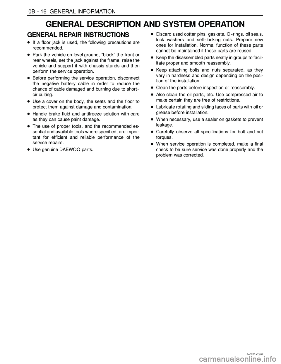
GENERAL DESCRIPTION AND SYSTEM OPERATION
GENERAL REPAIR INSTRUCTIONS
DIf a floor jack is used, the following precautions are
recommended.
DPark the vehicle on level ground, “block” the front or
rear wheels, set the jack against the frame, raise the
vehicle and support it with chassis stands and then
perform the service operation.
DBefore performing the service operation, disconnect
the negative battery cable in order to reduce the
chance of cable damaged and burning due to short --
cir cuiting.
DUse a cover on the body, the seats and the floor to
protect them against damage and contamination.
DHandle brake fluid and antifreeze solution with care
as they can cause paint damage.
DThe use of proper tools, and the recommended es-
sential and available tools where specified, are impor-
tant for efficient and reliable performance of the
service repairs.
DUse genuine DAEWOO parts.DDiscard used cotter pins, gaskets, O -- rings, oil seals,
lock washers and self -- locking nuts. Prepare new
ones for installation. Normal function of these parts
cannot be maintained if these parts are reused.
DKeep the disassembled parts neatly in groups to facil-
itate proper and smooth reassembly.
DKeep attaching bolts and nuts separated, as they
vary in hardness and design depending on the posi-
tion of the installation.
DClean the parts before inspection or reassembly.
DAlso clean the oil parts, etc. Use compressed air to
make certain they are free of restrictions.
DLubricate rotating and sliding faces of parts with oil or
grease before installation.
DWhen necessary, use a sealer on gaskets to prevent
leakage.
DCarefully observe all specifications for bolt and nut
torques.
DWhen service operation is completed, make a final
check to be sure service was done properly and the
problem was corrected.
Page 22 of 2053
1A1 -- 2 GENERAL ENGINE INFORMATION
D AEW OO M Y_2000
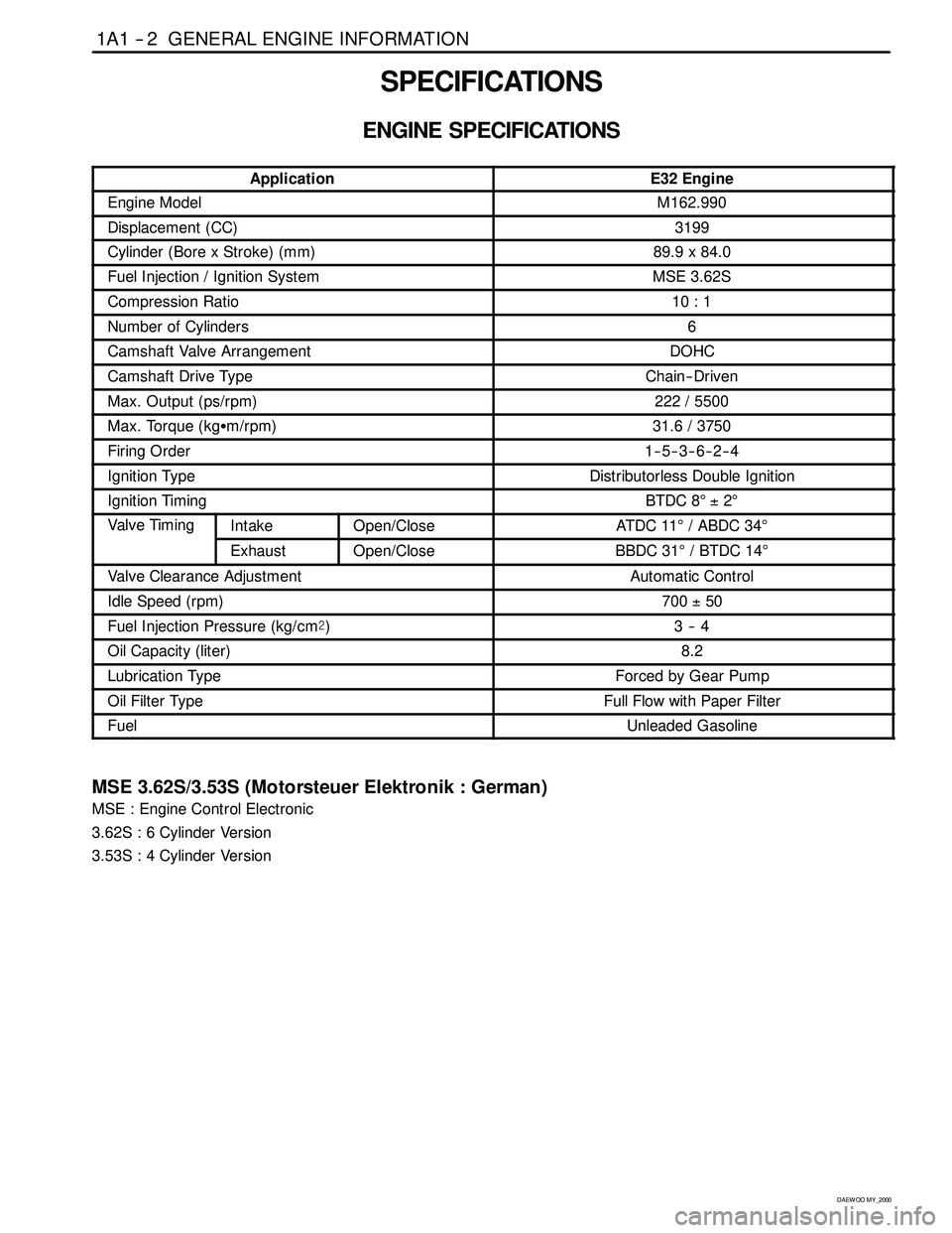
SPECIFICATIONS
ENGINE SPECIFICATIONS
ApplicationE32 Engine
Engine ModelM162.990
Displacement (CC)3199
Cylinder (Bore x Stroke)(mm)89.9 x 84.0
Fuel Injection / Ignition SystemMSE 3.62S
Compression Ratio10 : 1
Number of Cylinders6
Camshaft Valve ArrangementDOHC
Camshaft Drive TypeChain-- Driven
Max. Output (ps/rpm)222 / 5500
Max. Torque (kgSm/rpm)31.6 / 3750
Firing Order1--5--3--6--2--4
Ignition TypeDistributorless Double Ignition
Ignition TimingBTDC 8°±2°
Valve TimingIntakeOpen/CloseAT DC 11°/ ABDC 34°g
ExhaustOpen/CloseBBDC 31°/BTDC14°
Valve Clearance AdjustmentAutomatic Control
Idle Speed (rpm)700±50
Fuel Injection Pressure (kg/cm@)3--4
Oil Capacity (liter)8.2
Lubrication TypeForced by Gear Pump
Oil Filter TypeFull Flow with Paper Filter
FuelUnleaded Gasoline
MSE 3.62S/3.53S (Motorsteuer Elektronik : German)
MSE : Engine Control Electronic
3.62S : 6 Cylinder Version
3.53S : 4 Cylinder Version
Page 35 of 2053
M162 ENGINE MECHANICAL 1B1 -- 3
D AEW OO M Y_2000
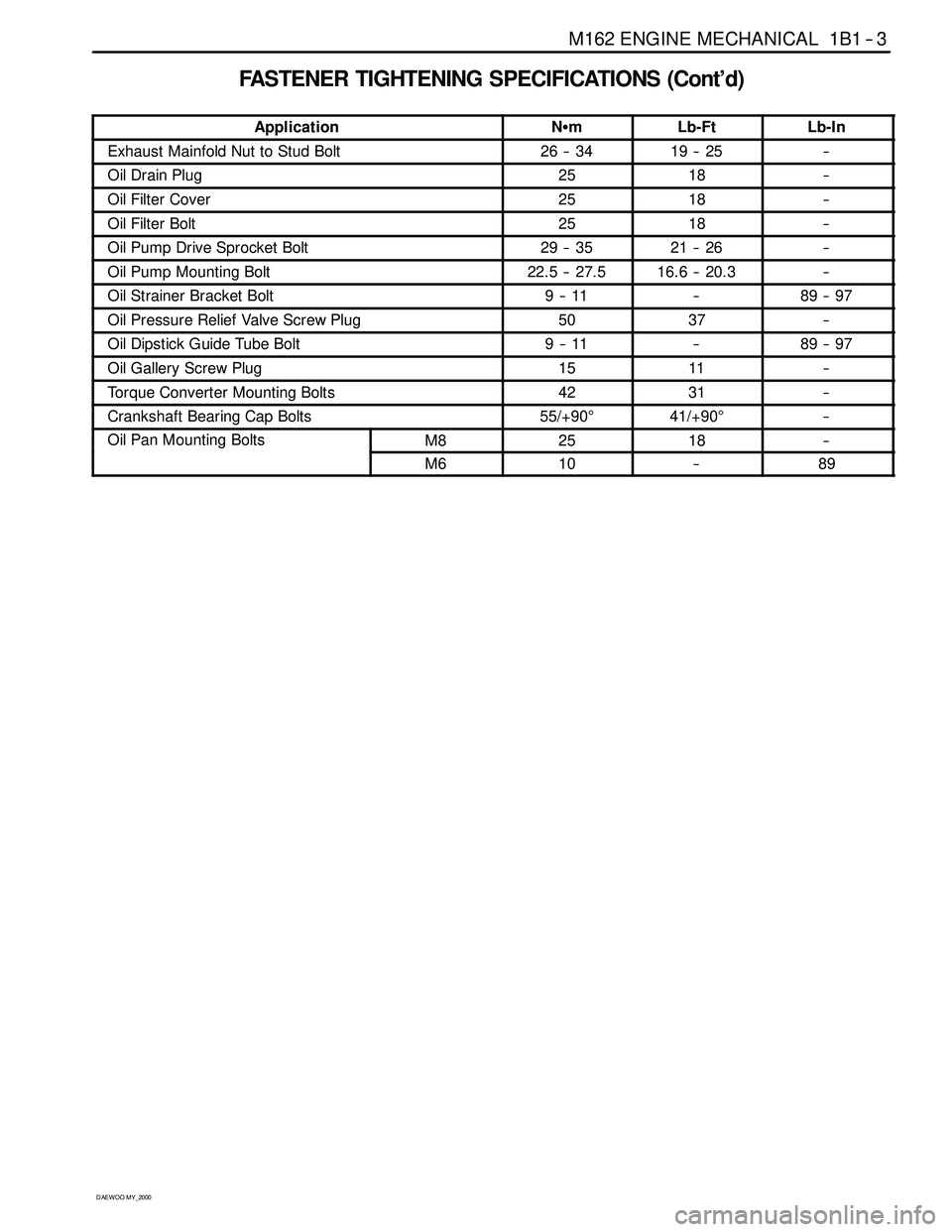
FASTENER TIGHTENING SPECIFICATIONS (Cont’d)
ApplicationNSmLb-FtLb-In
Exhaust Mainfold Nut to Stud Bolt26 -- 3419 -- 25--
Oil Drain Plug2518--
Oil Filter Cover2518--
Oil Filter Bolt2518--
Oil Pump Drive Sprocket Bolt29 -- 3521 -- 26--
Oil Pump Mounting Bolt22.5 -- 27.516.6 -- 20.3--
Oil Strainer Bracket Bolt9--11--89 -- 97
Oil Pressure Relief Valve Screw Plug5037--
Oil Dipstick Guide Tube Bolt9--11--89 -- 97
Oil Gallery Screw Plug1511--
Torque Converter Mounting Bolts4231--
Crankshaft Bearing Cap Bolts55/+90°41/+90°--
Oil Pan Mounting BoltsM82518--g
M610--89
Page 40 of 2053
1B1 -- 8 M162 ENGINE MECHANICAL
D AEW OO M Y_2000
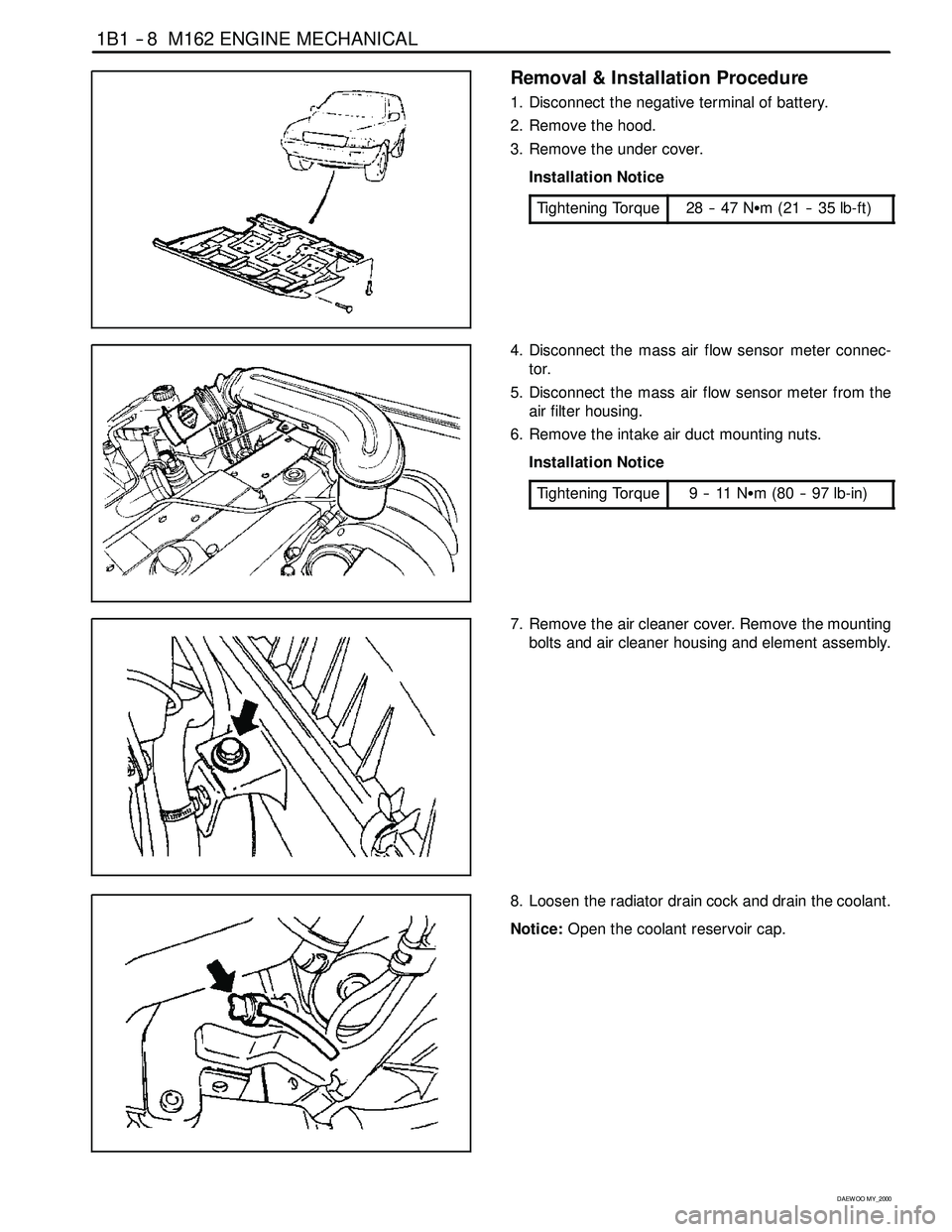
Removal & Installation Procedure
1. Disconnect the negative terminal of battery.
2. Remove the hood.
3. Remove the under cover.
Installation Notice
Tightening Torque
28 -- 47 NSm (21 -- 35 lb-ft)
4. Disconnect the mass air flow sensor meter connec-
tor.
5. Disconnect the mass air flow sensor meter from the
air filter housing.
6. Remove the intake air duct mounting nuts.
Installation Notice
Tightening Torque
9--11NSm (80 -- 97 lb-in)
7. Remove the air cleaner cover. Remove the mounting
bolts and air cleaner housing and element assembly.
8. Loosen the radiator drain cock and drain the coolant.
Notice:Open the coolant reservoir cap.
Page 41 of 2053
M162 ENGINE MECHANICAL 1B1 -- 9
D AEW OO M Y_2000
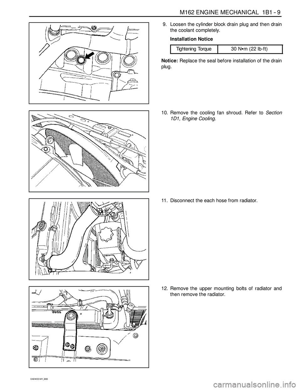
9. Loosen the cylinder block drain plug and then drain
the coolant completely.
Installation Notice
Tightening Torque
30 NSm (22 lb-ft)
Notice:Replace the seal before installation of the drain
plug.
10. Remove the cooling fan shroud. Refer toSection
1D1, Engine Cooling.
11. Disconnect the each hose from radiator.
12. Remove the upper mounting bolts of radiator and
then remove the radiator.
Page 42 of 2053

1B1 -- 10 M162 ENGINE MECHANICAL
D AEW OO M Y_2000
13. Remove the hydraulic pipe of power steering.
Notice:Completely drain the oil.
14. Discharge the refrigerant from A/C system, and dis-
connect the discharge pipe and suction pipe from
the compressor. Refer toSection 7B, Manual Con-
trol Heating, Ventilation, and Air Conditioning Sys -
tem.
15. Remove the fuel feed and return line.
Notice:Before removing the fuel lines, release the pres-
sure in the fuel system.
Installation Notice
Tightening Torque
21 -- 25 NSm (15 -- 18 lb-ft)
16. Disconnect the terminals from the generator.
Page 44 of 2053
1B1 -- 12 M162 ENGINE MECHANICAL
D AEW OO M Y_2000
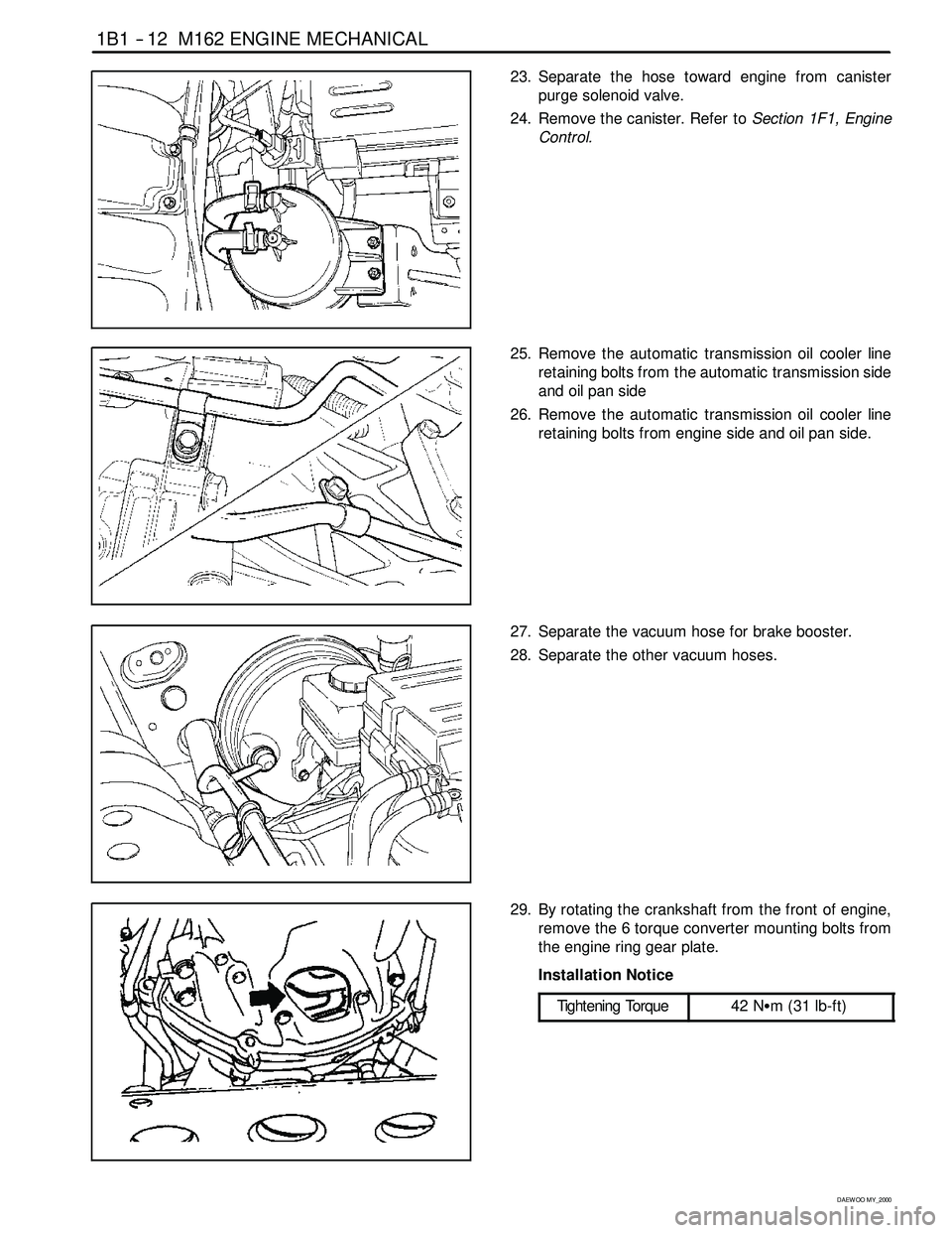
23. Separate the hose toward engine from canister
purge solenoid valve.
24. Remove the canister. Refer toSection 1F1, Engine
Control.
25. Remove the automatic transmission oil cooler line
retaining bolts from the automatic transmission side
and oil pan side
26. Remove the automatic transmission oil cooler line
retaining bolts from engine side and oil pan side.
27. Separate the vacuum hose for brake booster.
28. Separate the other vacuum hoses.
29. By rotating the crankshaft from the front of engine,
remove the 6 torque converter mounting bolts from
the engine ring gear plate.
Installation Notice
Tightening Torque
42 NSm (31 lb-ft)
Page 45 of 2053

M162 ENGINE MECHANICAL 1B1 -- 13
D AEW OO M Y_2000
30. Remove the exhaust manifold and exhaust pipe.
Installation Notice
Tightening Torque
30 NSm (22 lb-ft)
31. Remove the transmission.Refer to Section 5A, Au-
tomatic Transmission.
32. Install a chain to the bracket of engine, by using a
hoist or crane.
33. Remove the engine mount nuts.
Installation Notice
Tightening Torque
70 NSm (52 lb-ft)
34. Carefully separate the engine assembly from the ve-
hicle.
35. Installation should follow the removal procedure in
the reverse order.