torque SSANGYONG KORANDO 1997 Service Owner's Manual
[x] Cancel search | Manufacturer: SSANGYONG, Model Year: 1997, Model line: KORANDO, Model: SSANGYONG KORANDO 1997Pages: 2053, PDF Size: 88.33 MB
Page 71 of 2053

M162 ENGINE MECHANICAL 1B1 -- 39
D AEW OO M Y_2000
Tools Required
601 589 03 14 00 Crankshaft Front Seal Installer
Replacement Procedure
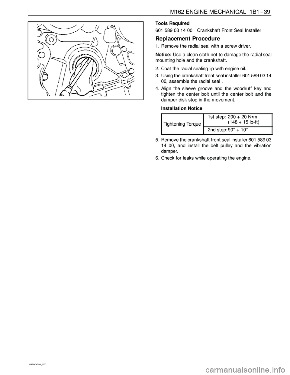
1. Remove the radial seal with a screw driver.
Notice:Use a clean cloth not to damage the radial seal
mounting hole and the crankshaft.
2. Coat the radial sealing lip with engine oil.
3. Using the crankshaft front seal installer 601 589 03 14
00, assemble the radial seal .
4. Align the sleeve groove and the woodruff key and
tighten the center bolt until the center bolt and the
damper disk stop in the movement.
Installation Notice
Ti
ghteningTo rque
1st step: 200 + 20 NSm
(148 + 15 lb-ft)
TighteningTorque
2nd step: 90°+10°
5. Remove the crankshaft front seal installer 601 589 03
14 00, and install the belt pulley and the vibration
damper.
6. Check for leaks while operating the engine.
Page 76 of 2053

1B1 -- 44 M162 ENGINE MECHANICAL
D AEW OO M Y_2000
Removal & Installation Procedure
1. Unscrew the connecting rod bearing cap bolt and re-
move the bearing cap.
Installation Notice
Tightening Torque
40 NSm (30 lb-ft) + 90°
DMake sure that the upper and lower bearing shells
do not change each other.
DCoat the bearing shell with engine oil.
DInstall the bearing cap according to the consecu-
tive number.
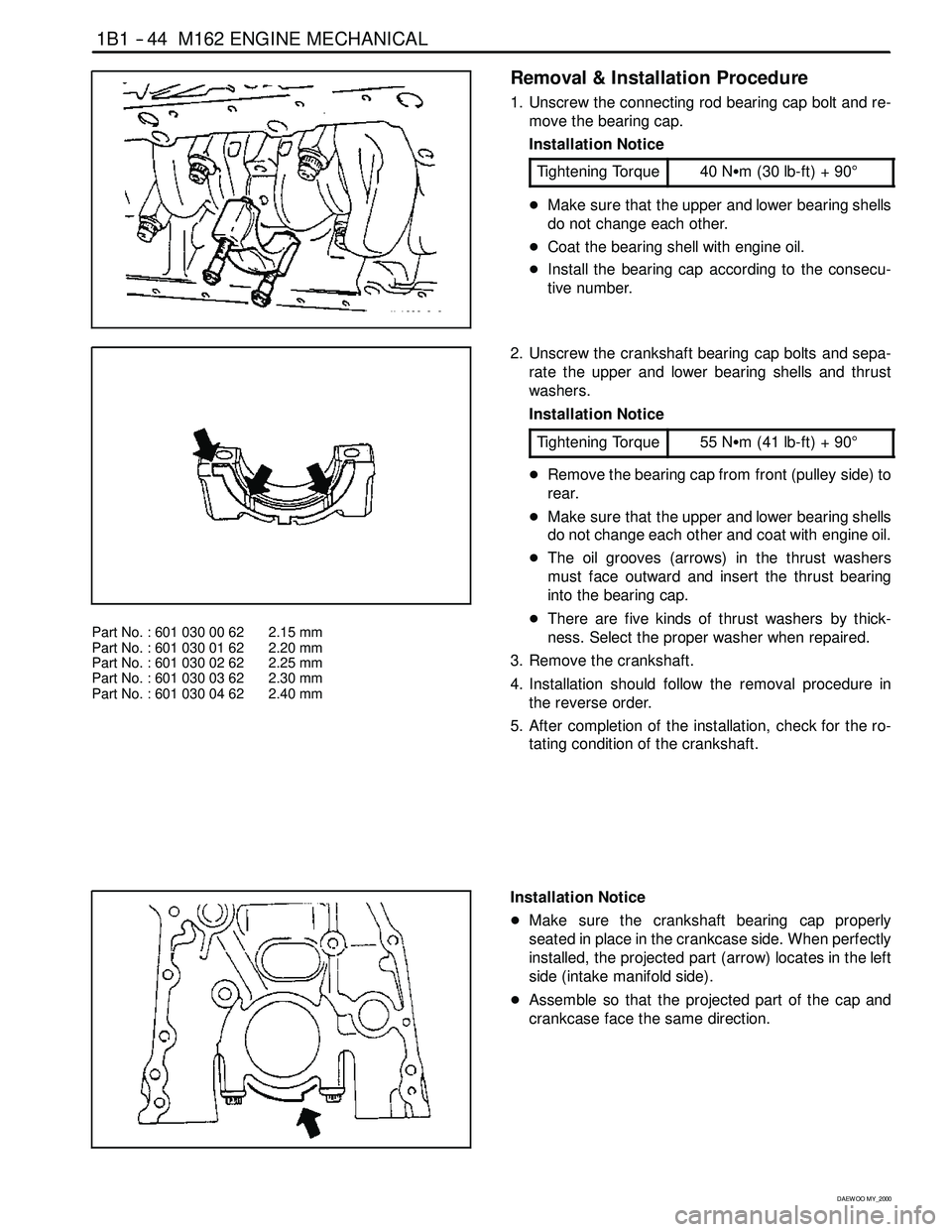
Part No. : 601 030 00 62 2.15 mm
Part No. : 601 030 01 62 2.20 mm
Part No. : 601 030 02 62 2.25 mm
Part No. : 601 030 03 62 2.30 mm
Part No. : 601 030 04 62 2.40 mm
2. Unscrew the crankshaft bearing cap bolts and sepa-
rate the upper and lower bearing shells and thrust
washers.
Installation Notice
Tightening Torque
55 NSm (41 lb-ft) + 90°
DRemove the bearing cap from front (pulley side) to
rear.
DMake sure that the upper and lower bearing shells
do not change each other and coat with engine oil.
DThe oil grooves (arrows) in the thrust washers
must face outward and insert the thrust bearing
into the bearing cap.
DThere are five kinds of thrust washers by thick-
ness. Select the proper washer when repaired.
3. Remove the crankshaft.
4. Installation should follow the removal procedure in
the reverse order.
5. After completion of the installation, check for the ro-
tating condition of the crankshaft.
Installation Notice
DMake sure the crankshaft bearing cap properly
seated in place in the crankcase side. When perfectly
installed, the projected part (arrow) locates in the left
side (intake manifold side).
DAssemble so that the projected part of the cap and
crankcase face the same direction.
Page 79 of 2053

M162 ENGINE MECHANICAL 1B1 -- 47
D AEW OO M Y_2000
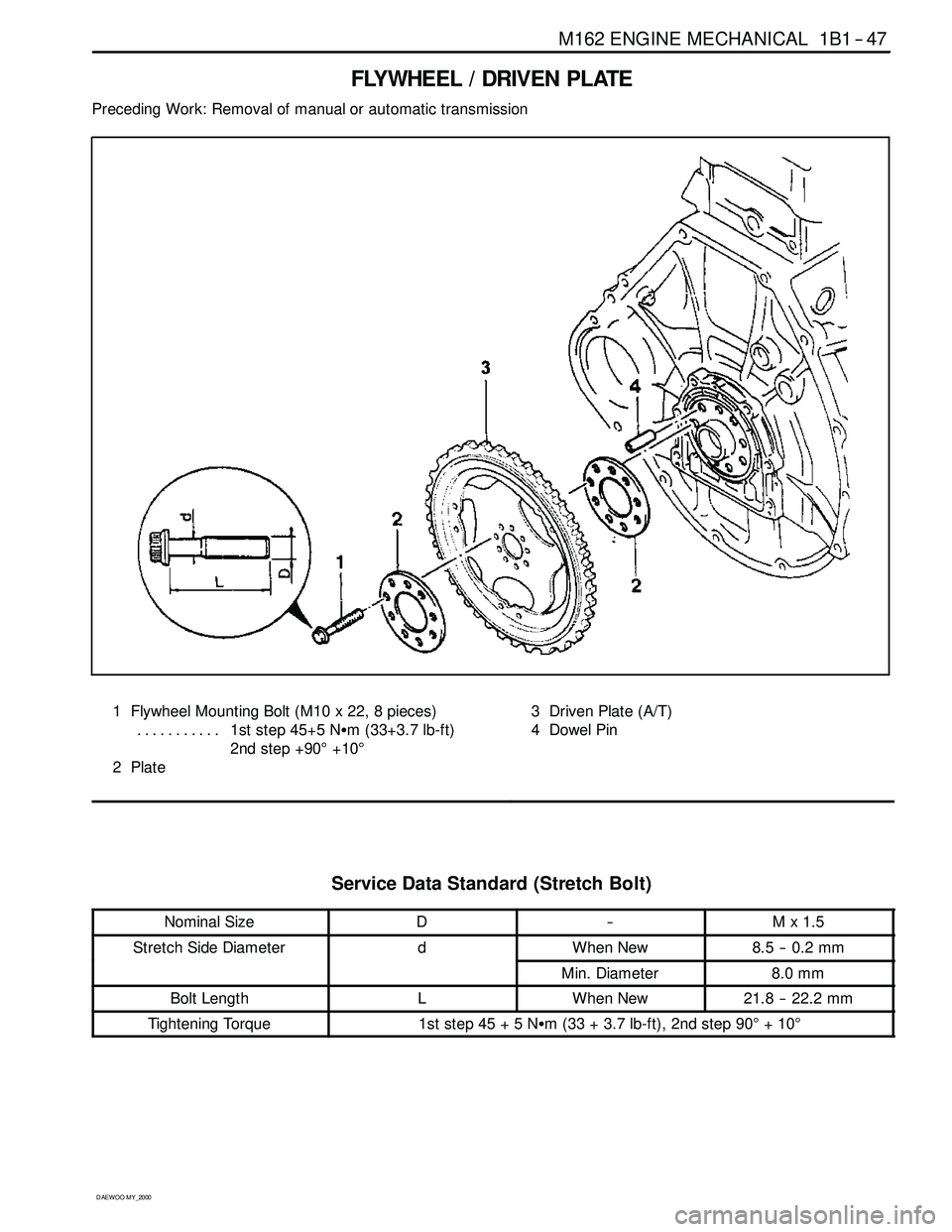
FLYWHEEL / DRIVEN PLATE
Preceding Work: Removal of manual or automatic transmission
1 Flywheel Mounting Bolt (M10 x 22, 8 pieces)
1st step 45+5 NSm (33+3.7 lb-ft) ...........
2nd step +90°+10°
2Plate3 Driven Plate (A/T)
4 Dowel Pin
Service Data Standard (Stretch Bolt)
Nominal SizeD--Mx1.5
Stretch Side DiameterdWhen New8.5 -- 0.2 mm
Min. Diameter8.0 mm
Bolt LengthLWhen New21.8 -- 22.2 mm
Tightening Torque1ststep45+5NSm (33 + 3.7 lb-ft), 2nd step 90°+10°
Page 80 of 2053

1B1 -- 48 M162 ENGINE MECHANICAL
D AEW OO M Y_2000
Removal & Installation Procedure
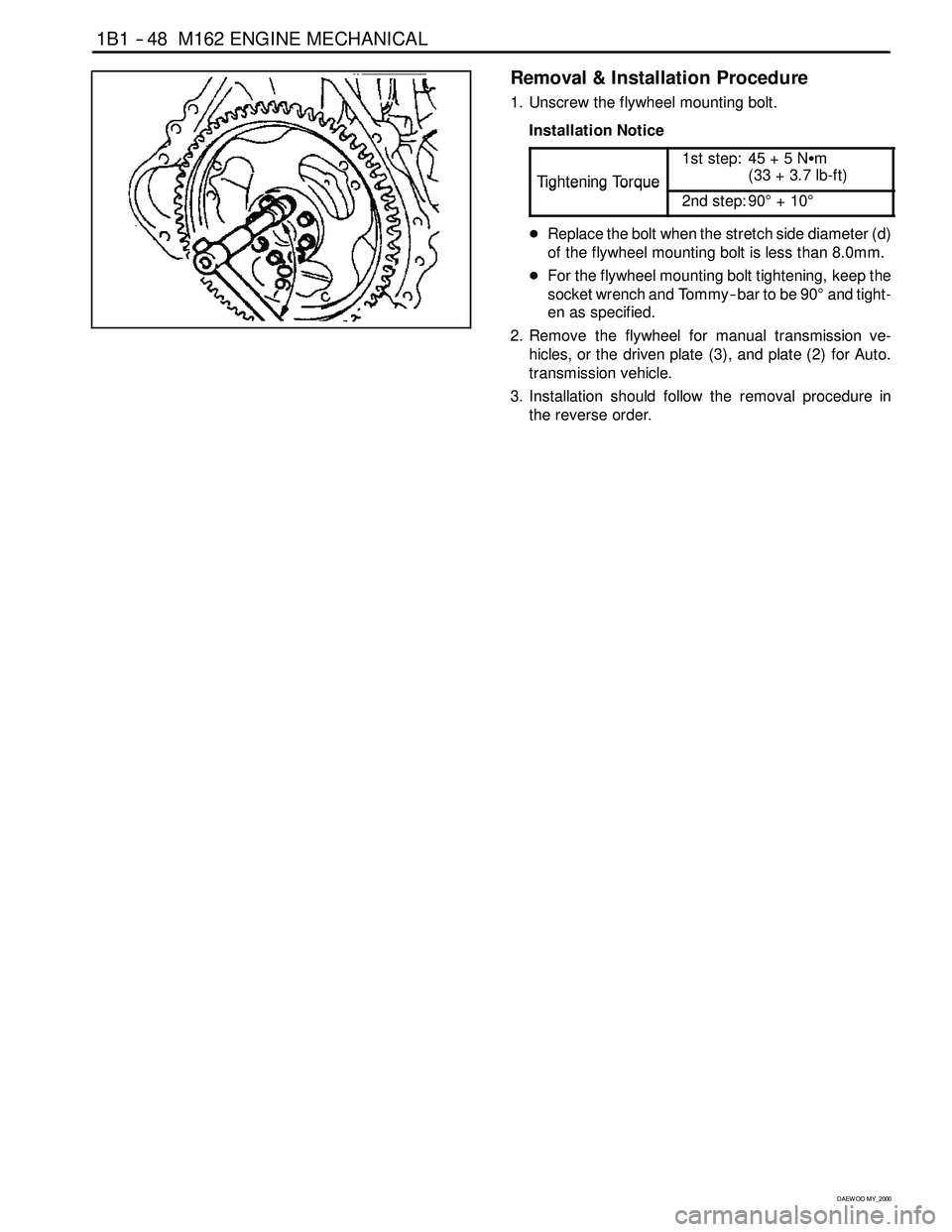
1. Unscrew the flywheel mounting bolt.
Installation Notice
Ti
ghteningTo rque
1st step: 45 + 5 NSm
(33+3.7lb-ft)
TighteningTorque
2nd step: 90°+10°
DReplace the bolt when the stretch side diameter (d)
of the flywheel mounting bolt is less than 8.0mm.
DFor the flywheel mounting bolt tightening, keep the
socket wrench and Tommy -- bar to be 90°and tight-
en as specified.
2. Remove the flywheel for manual transmission ve-
hicles, or the driven plate (3), and plate (2) for Auto.
transmission vehicle.
3. Installation should follow the removal procedure in
the reverse order.
Page 83 of 2053

M162 ENGINE MECHANICAL 1B1 -- 51
D AEW OO M Y_2000
Removal & Installation Procedure
1. Turn the crankshaft to the direction of engine rotation
and position the no.1 cylinder piston at TDC which the
camshaft is positioned at OT.
2. Remove the cylinder head front cover.
3. Paint the alignment marks (arrows) on the intake and
exhaust camshaft sprocket and the timing chain.
3 Bolt 13 Camshaft Sprocket
4 Amarture 18 Control Piston
6 Nut (M20 x 1.5) 22 Intake Camshaft
12 Seal Cover
4. Unscrew the bolt (3) from the armature (4) and re-
move the armature.
Installation Notice
Tightening Torque
35 NSm (26 lb-ft)
5. Unscrew the nut (6) and remove the ring and seal
cover (11).
Installation Notice
Tightening Torque
60 -- 70 NSm (44 -- 52 lb-ft)
6. Unscrew the sprocket bolt from the exhaust camshaft
and remove the sprocket.
Installation Notice
Ti
ghteningTo rque
1st step: 18 -- 22 NSm
(13 -- 16 lb-ft)
TighteningTorque
2nd step: 60°±5°
The sprocket bolt is designed to be used only once,
so always replace with new one.
Page 84 of 2053

1B1 -- 52 M162 ENGINE MECHANICAL
D AEW OO M Y_2000
7. Remove the camshaft sprocket (13) and adjust piston
(14), and remove the flange shaft (16) from the intake
camshaft (22) after removing the bolt (15).
Installation Notice
Ti
ghteningTo rque
1st step: 18 -- 22 NSm
(13 -- 16 lb-ft)
TighteningTorque
2nd step: 60°±5°
The sprocket bolt is designed to be used only once,
so always replace with new one.
8. Installation should follow the removal procedure in
the reverse order.
9. Adjust the camshaft timing.
CAMSHAFT SPROCKET BOLT
Intake Flange Shaft Bolt
TighteningTo rque
1st step: 18 -- 22 NSm
(13 -- 16 lb-ft)
TighteningTorque
2nd step: 60°±5°
Notice:The sprocket bolts are designed to be used only
once, so always replace with new one.
C. M7 x 13 Collar Bolt Torx -- T30
e. 6.8 mm
16. Flange Shaft
18. Control Piston
22. Intake Camshaft
Page 85 of 2053

M162 ENGINE MECHANICAL 1B1 -- 53
D AEW OO M Y_2000
Exhaust Camshaft Sprocket Bolt
TighteningTo rque
1st step: 18 -- 22 NSm
(13 -- 16 lb-ft)
TighteningTorque
2nd step: 60°±5°
Notice:The sprocket bolts are designed to be used only
once, so always replace with new one.
E. M7 x 13 Collar Bolt Torx -- T30
e. 6.8 mm
13a. Camshaft Sprocket
22a. Exhaust Camshaft
Page 88 of 2053

M162 ENGINE MECHANICAL 1B1 -- 61
D AEW OO M Y_2000
10. Install the chain to the exhaust camshaft sprocket
and install it to the camshaft.
Installation Notice (Sprocket Bolt)
Ti
ghteningTo rque
1st step: 18 -- 22 NSm
(13 -- 16 lb-ft)
TighteningTorque
2nd step: 60°±5°
The sprocket bolt is designed to be used only once,
so replace with new one.
11. Install the chain tensioner.
Installation Notice
Ti
ghteningScrew Plug40 NSm
(30 lb-ft)
Tightening
TorqueTensioner
Assembly72 -- 88 NSm
(53 -- 65 lb-ft)
12. Check the camshaft timing.
Page 90 of 2053

M162 ENGINE MECHANICAL 1B1 -- 63
D AEW OO M Y_2000
Tools Required
111 589 01 59 00 Supporting Bar
111 589 18 61 00 Lever Pusher
111 589 25 63 00 Thrust Piece
602589004000 EngineLock
DW110-- 090 Connecting Hose
DW110-- 100 Valve Tappet Remover
Removal & Installation Procedure
1. Place the supporting bar 111 589 01 59 00 (a) at the
camshaft bearing cap and tighten them with the bear-
ing cap bolt.
Installation Notice
Tightening Torque
22.5 -- 27.5 NSm
(16.6 -- 20.3 lb-ft)
2. Turn the crankshaft to position the each cylinder pis-
ton at TDC.
Mark on The Vibration Damper
Cylinder
OT1, 6
120°2, 5
240°3, 4
Notice
DRemove the valve spring only at TDC.
DAlways rotate the crankshaft by holding the chain to
prevent from timing chain damage and tangling, and
for smooth rotation.
Page 95 of 2053

1B1 -- 68 M162 ENGINE MECHANICAL
D AEW OO M Y_2000
4. Carefully unscrew the screw plug (1), and remove the
seal (2).
Notice
DFor the removal of screw plug, be careful that it can
be jumped out due to the force of compression
spring.
DRemove the screw plug only when the seal and com-
pression spring are damaged.
5. Carefully remove the filler pin (3), compression spring
(4), snap ring (5), and the thrust pin (6).
6. Remove the chain tensioner housing (7) and the seal
(8).
Installation Procedure
1. Connect the thrust pin (6) and the snap ring (5) to the
chain tensioner housing (7).
Notice:When connecting the thrust pin, push in the
thrust pin far enough so that it doesn’t protrude at the
chain tensioner housing.
2. Install the chain tensioner housing (7), thrust pin (6),
snap ring (5), and the seal (8).
Installation Notice
Tightening Torque
72 -- 88 NSm (53 -- 65 lb-ft)
3. Insert the compression spring (4) with the filler pin (3)
into chain tensioner housing.