Idle control SSANGYONG KORANDO 1997 Service Workshop Manual
[x] Cancel search | Manufacturer: SSANGYONG, Model Year: 1997, Model line: KORANDO, Model: SSANGYONG KORANDO 1997Pages: 2053, PDF Size: 88.33 MB
Page 810 of 2053
OM600 ENGINE CONTROLS 1F3 -- 7
D AEW OO M Y_2000
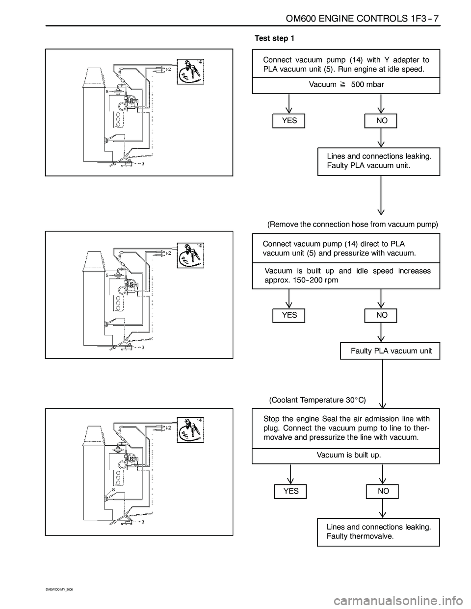
Test step 1
Connect vacuum pump (14) with Y adapter to
PLA vacuum unit (5). Run engine at idle speed.
Vacuum≧500 mbar
YES
NO
Faulty PLA vacuum unit
(Coolant Temperature 30_C)
Connect vacuum pump (14) direct to PLA
vacuum unit (5) and pressurize with vacuum.
YES
NO
Lines and connections leaking.
Faulty PLA vacuum unit.
(Remove the connection hose from vacuum pump)
Vacuum is built up and idle speed increases
approx. 150-- 200 rpm
YESNO
Lines and connections leaking.
Faulty thermovalve.
Stop the engine Seal the air admission line with
plug. Connect the vacuum pump to line to ther-
movalve and pressurize the line with vacuum.
Vacuum is built up.
Page 812 of 2053
OM600 ENGINE CONTROLS 1F3 -- 9
D AEW OO M Y_2000
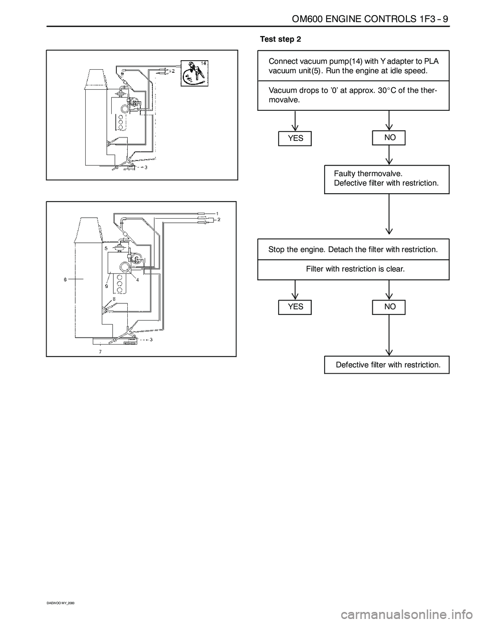
Test step 2
Connect vacuum pump(14) with Y adapter to PLA
vacuum unit(5). Run the engine at idle speed.
Vacuum drops to ’0’ at approx. 30_C of the ther-
movalve.
YES
NO
Defective filter with restriction.
Stop the engine. Detach the filter with restriction.
YES
NO
Faulty thermovalve.
Defective filter with restriction.
Filter with restriction is clear.
Page 1132 of 2053
5A-38 AUTOMATIC TRANSMISSION
SSANGYONG MY2002
DIAGNOSIS
BASIC KNOWLEDGE REQUIRED
You must be familliar with some basic electronics to
use this section of the Service Manual. They will help
you to follow diagnostic procedures.
Notice: Lack of the basic knowledge of this transmis-
sion when performing diagnostic procedures could re-
sult in incorrect diagnostic performance or damage to
transmission components. Do not, under any circum-
stances, attempt to diagnose a transmission problem
without this basic knowledge.
Notice: If a wire is probed with a sharp instrument
and not properly sealed afterward, the wire will corrode
and an open circuit will result.
Diagnostic test probes are now available that allow
you to probe individual wires without leaving the wire
open to the environment. These probe devices are
inexpensive and easy to install, and they permanently
seal the wire from corrosion.
Special Tools
You should be able to use a Digital Volt Meter (DVM),
a circuit tester, jumper wires or leads and a line
pressure gauge set. The functional check procedure
is designed to verify the correct operation of electronic
components in the transmission. This will eliminate the
unnecessary removal of transmission components.
FUNCTIONAL CHECK
PROCEDURE
Begin with the Functional Check Procedure which pro-
vides a general outline of how to diagnose automatic
transmission. The following functional check procedure
will indicate the proper path of diagnosing the transmis-
sion by describing the basic checks and then referenc-
ing the locations of the specific checks.
Check the fluid level according to the Fluid Level
Service Procedure.
Check the transmission fluid leak.
Check if the transmission fluid is not burnt by smell.
Notice: The specific fluid used in this transmission
turns brown during normal operation. Brown fluid
does not indicate a transmission fault.
Ensure that the transmission is not in Limp Home
Mode (LHM).
Check the battery terminals and the earth connec-
tions for corrosion or looseness.
Check that the cooler flow is not restricted.
Check all electrical plug connections for tightness.
Use on-board diagnostic tool or a scan tool to see
if any transmission trouble codes have been set.
DIAGNOSTIC INFORMATION AND PROCEDURES
Refer to the appropriate “Diagnostic Trouble Code
(DTC)” information and repair the vehicle as
directed. After repairing the vehicle, perform the
road test and verify that the code has not set again.
Perform the Electrical/Garage Shift Tests.
Perform the Road Test Procedure in this section.
Inspect the oil and check for metal or other contami-
nants in the oil pan.
TRANSMISSION FLUID LEVEL
SERVICE PROCEDURE
This procedure is to be used when checking a concern
with the fluid level in a vehicle. A low fluid level will
result in slipping and loss of drive/ reverse or delay on
engagement of drive/ reverse when the vehicle is cold.
The vehicle is first checked for transmission diagnostic
messages on the scan tool. If the oil level is low, it is
possible to register a vehicle speed signal fault.
The vehicle is to be test driven to determine if there is
an abnormal delay when selecting drive or reverse, or
loss of drive. One symptom of low fluid level is a
momentary loss of drive when driving the vehicle around
a corner. Also when the transmission fluid level is low,
a loss of drive may occur when the transmission fluid
temperature is low.
If there is no loss of drive when the vehicle is driven
warm and a vehicle speed signal fault is registered,
then fluid should be added to the transmission.
When adding or changing transmission fluid use only
Castrol TQ 95 automatic transmission fluid. The use of
incorrect fluid will cause the performance and durability
of the transmission to be severely degraded.
Fluid Level Diagnosis procedure
1. If the vehicle is at operating temperature allow the
vehicle to cool down for two hours, but no greater
than four hours. Or if the vehicle is at cool status,
start the engine and allow the engine to idle for
approximately 5 minutes or, if possible, drive the
vehicle for a few kilometers. This will allow the
transmission to be within the correct temperature
range. Transmission fluid level should be checked
at temperature 50 - 60 °C (82 - 140 °F).
Caution: Removal of the fluid filler plug when
the transmission fluid is hot may cause injury if
fluid drains from the filler hole.
2. With the brake pedal pressed, move the gear shift
control lever through the gear ranges, pausing a
few seconds in each range. Return the gear shift
control lever to P (Park). Turn the engine OFF.
3. Park the vehicle on a hoist, inspection pit or similar
raised level surface. The vehicle must be control
level to obtain a correct fluid level measurement.
Page 1134 of 2053
5A-40 AUTOMATIC TRANSMISSION
SSANGYONG MY2002
Dye and Black Light Method
1. Add dye to the transmission through the transmission
fluid filler plug. Follow the manufacturer’s recommen-
dation for the amount of dye to be used.
2. Use the black light to find the fluid leak.
3. Make the necessary repairs.
Repairing the Fluid Leak
Once the leak point is found the source of the leak
must be determined. The following list describes the
potential causes for the leak:
Fasteners are not torqued to specification.
Fastener threads and fastener holes are dirty or
corroded.
Gaskets, seals or sleeves are misaligned, damaged
or worn.
Damaged, warped or scratched seal bore or gasket
surface.
Loose or worn bearing causing excess seal or sleeve
wear.
Case or component porosity.
Fluid level is too high.
Plugged vent or damaged vent tube.
Water or coolant in fluid.
Fluid drain back holes plugged.
ELECTRICAL / GARAGE SHIFT
TEST
This preliminary test should be performed before a hoist
or road test to make sure electronic control inputs are
connected and operating. If the inputs are not checked
before operating the transmission, a simple electrical
condition could be misdiagnosed as a major
transmission condition.
A scan tool provides valuable information and must
be used on the automatic transmission for accurate
diagnosis.
1. Move gear shift control lever to P (Park) and set
the parking brake.
2. Connect scan tool to Data Link Connector (DLC)
terminal.
3. Start engine.
4. Turn the scan tool ON.
5. Verify that the appropriate signals are present.
These signals may include:
ENGINE SPEED
VEHICLE SPEED
THROTTLE POSITION
ACCEL. PEDAL POSITION
TRANSMISSION GEAR STATE
GEAR SHIFT LEVER POSITION
TRANSMISSION FLUID TEMPERATURE
CLOSED THROTTLE POSITION LEARN
OPEN THROTTLE POSITION LEARNT
CLOSED ACCEL. PEDAL POSITION LEARNT
OPEN ACCEL. PEDAL POSITION LEARNT
A/C COMPRESSOR STATUS
KICKDOWN SWITCH STATUS
4WD STATUS
MODE SWITCH
THROTTLE POSITION VOLTAGE
GEAR SHIFT LEVER POSITION VOLTAGE
TRANS. FLUID TEMPERATURE VOLTAGE
A/C SWITCH
KICKDOWN SWITCH VOLTAGE
4WD LAMP LOW VOLTAGE
4WD LAMP HIGH VOLTAGE
MODE SWITCH VOLTAGE
BATTERY VOLTAGE
6. Monitor the A/C COMPRESSOR STATUS signal
while pushing the A/C switch.
The A/C COMPRESSOR STATUS should come
ON when the A/C switch is pressed, and turn
OFF when the A/C switch is repushed.
7. Monitor the GEAR SHIFT LEVER POSITION signal
and move the gear shift control lever through all
the ranges.
Verify that the GEAR SHIFT LEVER POSITION
value matches the gear range indicated on the
instrument panel or console.
Gear selections should be immediate and not
harsh.
8. Move gear shift control lever to neutral and monitor
the THROTTLE POSITION signal while increasing
and decreasing engine speed with the accelerator
pedal.
THROTTLE POSITION should increase with en-
gine speed.
ROAD TEST PROCEDURE
Perform the road test using a scan tool.
This test should be performed when traffic and road
conditions permit.
Observe all traffic regulations.
ELECTRONIC ADJUSTMENTS
Idle Speed Adjustments
Carry out the adjustments to the idle speed as detailed
in the workshop manual.
Vehicle Coding
The vehicle coding is integrated as part of the
diagnostic software. A scan tool has the function to
code the ve-hicle through the K-line.
Page 1135 of 2053
5A-40 AUTOMATIC TRANSMISSION
SSANGYONG MY2002
Dye and Black Light Method
1. Add dye to the transmission through the transmission
fluid filler plug. Follow the manufacturer’s recommen-
dation for the amount of dye to be used.
2. Use the black light to find the fluid leak.
3. Make the necessary repairs.
Repairing the Fluid Leak
Once the leak point is found the source of the leak
must be determined. The following list describes the
potential causes for the leak:
Fasteners are not torqued to specification.
Fastener threads and fastener holes are dirty or
corroded.
Gaskets, seals or sleeves are misaligned, damaged
or worn.
Damaged, warped or scratched seal bore or gasket
surface.
Loose or worn bearing causing excess seal or sleeve
wear.
Case or component porosity.
Fluid level is too high.
Plugged vent or damaged vent tube.
Water or coolant in fluid.
Fluid drain back holes plugged.
ELECTRICAL / GARAGE SHIFT
TEST
This preliminary test should be performed before a hoist
or road test to make sure electronic control inputs are
connected and operating. If the inputs are not checked
before operating the transmission, a simple electrical
condition could be misdiagnosed as a major
transmission condition.
A scan tool provides valuable information and must
be used on the automatic transmission for accurate
diagnosis.
1. Move gear shift control lever to P (Park) and set
the parking brake.
2. Connect scan tool to Data Link Connector (DLC)
terminal.
3. Start engine.
4. Turn the scan tool ON.
5. Verify that the appropriate signals are present.
These signals may include:
ENGINE SPEED
VEHICLE SPEED
THROTTLE POSITION
ACCEL. PEDAL POSITION
TRANSMISSION GEAR STATE
GEAR SHIFT LEVER POSITION
TRANSMISSION FLUID TEMPERATURE
CLOSED THROTTLE POSITION LEARN
OPEN THROTTLE POSITION LEARNT
CLOSED ACCEL. PEDAL POSITION LEARNT
OPEN ACCEL. PEDAL POSITION LEARNT
A/C COMPRESSOR STATUS
KICKDOWN SWITCH STATUS
4WD STATUS
MODE SWITCH
THROTTLE POSITION VOLTAGE
GEAR SHIFT LEVER POSITION VOLTAGE
TRANS. FLUID TEMPERATURE VOLTAGE
A/C SWITCH
KICKDOWN SWITCH VOLTAGE
4WD LAMP LOW VOLTAGE
4WD LAMP HIGH VOLTAGE
MODE SWITCH VOLTAGE
BATTERY VOLTAGE
6. Monitor the A/C COMPRESSOR STATUS signal
while pushing the A/C switch.
The A/C COMPRESSOR STATUS should come
ON when the A/C switch is pressed, and turn
OFF when the A/C switch is repushed.
7. Monitor the GEAR SHIFT LEVER POSITION signal
and move the gear shift control lever through all
the ranges.
Verify that the GEAR SHIFT LEVER POSITION
value matches the gear range indicated on the
instrument panel or console.
Gear selections should be immediate and not
harsh.
8. Move gear shift control lever to neutral and monitor
the THROTTLE POSITION signal while increasing
and decreasing engine speed with the accelerator
pedal.
THROTTLE POSITION should increase with en-
gine speed.
ROAD TEST PROCEDURE
Perform the road test using a scan tool.
This test should be performed when traffic and road
conditions permit.
Observe all traffic regulations.
ELECTRONIC ADJUSTMENTS
Idle Speed Adjustments
Carry out the adjustments to the idle speed as detailed
in the workshop manual.
Vehicle Coding
The vehicle coding is integrated as part of the
diagnostic software. A scan tool has the function to
code the ve-hicle through the K-line.
Page 1170 of 2053

AUTOMATIC TRANSMISSION 5A-75
SSANGYONG MY2002
DTC P1708 TCM Supply Voltage Low
1Perform a Transmission Control Module (TCM) Diag-
nostic System Check.
Is the check performed?
1. Install the scan tool.
2. Turn the ignition ON, with the engine OFF.
3. Record and then clear DTCs.
4. Operate the vehicle within the conditions for
setting this DTC as specified in the text.
Does the scan tool display P1708?
1. Isolate the driven wheels from the ground and
apply the hand brake.
2. Start the engine and allow it to idle.
3. Move the gear lever to Drive.
4. Select the Ignition Voltage on the scan tool Data
List.
Is the Ignition Voltage less than the specified value?
While running the engine at the specified value, mea-
sure the battery voltage at the battery using a DVM.
Is the battery voltage greater than the specified value?
Check the fuse F23 for a malfunction and replace as
necessary?
Is a repair necessary?
1. Turn the ignition OFF.
2. Disconnect the TCM connector B.
3. Start the engine and raise the engine speed to
specified value.
4. While running the engine at the specified value,
measure the ignition voltage at the ignition feed
circuit terminal B30 using a DVM.
Is the ignition voltage greater than the specified value?
Check for a malfunctioning connection at the TCM
harness terminals and repair as necessary.
Is a repair necessary?
Repair the poor connection (high resistance) at the
ignition feed circuit.
Is the action complete?
1. Turn the ignition OFF.
2. Replace the TCM.
Is the action complete?
1. Using the scan tool, clear the DTCs.
2. Road test the vehicle within the conditions for
setting this DTC as specified in the text.
Does the scan tool indicate that this diagnostic has
run and passed?
Check if any DTCs are set.
Are there any DTCs displayed or previously recorded
at Step 2 that have not been diagnosed?
StepAction Value(s) Yes No
2
3
5
- Go to Step 10 Go to Step 9 6 4
- Go to Step 10 - 7
- Go to Step 10 - 8
- Go to Step 11 Go to Step 2 9
10
- Go to Step 2Go to “TCM
Diagnostic
System Check”
10 V Go to Step 4 Go to Step 10
- Go to Step 3 Go to
“Diagnostic
Aids”
11
-Go to
applicable
DTC tableSystem OK,
Check
Complete
- Go to Step 10 Go to Step 6
Idle in Drive
10 V Go to Step 7 Go to Step 8
Idle in Drive
12 V Go to Step 5 Go to Section
1E, Engine
Electrical
Page 1312 of 2053

SSANGYONG MY2002
5B-4 MANUAL TRANSMISSION
DIAGNOSTIC INFORMATION AND PROCEDURES
Control lever assembly broken or dam-
aged.
Damaged offset lever, shift fork, selector
place or selector arm.
Clutch not releasing.
Improper or low transmission oil.
Shift or shift rail binding.
Binding of sliding synchronizers or gears.
If reverse only, faulty backup switch.
Worn or damaged flywheel pilot bushing.
Engine idle speed too high.
Damaged or faulty clutch.
Pilot bearing between input shaft and
output shaft binding.
Damaged synchronizer.
Bell housing misaligned.
Damaged gear(s).
Worn or damaged flywheel pilot bushing.
Loosened transmission or flywheel
housing bolts, improper alignment.
Synchronizer damaged or excessively
worn.
Blocking ring damaged, worn index slots
or friction surfaces worn or damaged.
Excessive countershaft end play.
Worn or damaged fork due to loosened
shaft, rail or shifting fork.
Fork or offset lever loose on shaft or rail.
Worn or damaged forks, offset lever,
shaft or rail.Replace control lever and housing assem-
bly.
Remove extension, adapter or case
cover. Check or replace damaged parts.
Adjust or replace clutch.
Add or replace with specified oil.
Remove extension, adapter or case
cover. Check or replace damaged parts.
Remove extension, adapter or case
cover. Check synchronizers and gears
and replace damaged parts.
Check or replace backup switch.
Replace pilot bushing.
Adjust idle speed to specified speed.
Adjust or replace clutch.
Replace or check roller bearings.
Check or replace synchronizer parts.
Align bell housing and bore.
Check or replace gear(s).
Replace pilot bushing.
Tighten bolts to specified value. Realign
if necessary.
Check or replace synchronizer parts.
Check or replace blocking ring.
Check worn or damaged parts. Adjust
shim thickness using roller bearings if
necessary.
Check for wear or damaged. Replace
worn or damaged parts.
Replace extension, adapter or case
cover. Check or replace loose parts on
shaft or rail. Replace roll pin(s).
Remove extension, adapter or case
cover. Check for wear or damaged.
Replace damaged parts. Check Applicatio
Will not shift
(control lever moves)
Hard shift or control
lever will not move into
gear
Gears crash when
shifting
Transmission jumps
out
Transmission locked in
one gear
Action
Page 1314 of 2053

SSANGYONG MY2002
5B-6 MANUAL TRANSMISSION
DIAGNOSIS TABLE
Transmission Case
Extension Housing
Shift Cover / Shift Shaft
Shift Control Lever
Input Bearing Retainer
Input Gear Set
3rd Speed Gear Set
2nd Speed Gear Set
Reverse Speed Gear Set
1st Speed Gear Set
5th Speed Gear Set
Clutch Housing and Release Derive
Crankshaft Pilot Bushing and Release Bearing
Input Bearing
Main Shaft Input Bearing
Main Shaft Thrust Bearing
3rd Speed Gear Bearing
2nd Speed Gear Bearing
1st Speed Gear Bearing
Reverse Idler Gear Bushing
Counter Shaft Front Bearing
Counter Shaft Rear Bearing
Counter Shaft Thrust Bearing
5th Speed Drive Gear Bearing
Slip Yoke Bushing
Slip Yoke Seal
Speedometer Drive / Driven Gears
Speedometer Driven Gear Housing
Input Shaft Seal
1 - 2 Synchronizer Assembly
3 - 4 Synchronizer Assembly
5th Synchronizer Assembly Applicatio
1 Shift Hop-out
2 Shift Gear Crash
3 Shift Block-out
4 Hard Shift
5 Noise in Reverse Gear
6 Noise in 5th Gear
7 Noise in 4th Gear
8 Noise in 3rd Gear
9 Noise in 2nd Gear
10 Noise in 1st Gear
11 Noise in All Speeds
12 Leak at Transmission Rear Part
13 Leak at Transmission Center Part
14 Leak at Transmission Front
Possible Faulty Part
Page 1320 of 2053

SSANGYONG MY2002
5B-12 MANUAL TRANSMISSION
1 Remote Shift
2 Shift Lever
3 Shift Inner Boot
4 Lining Shift Socket
5 Control Housing Arm Insulator
6 Control Housing Arm
7 Bushing
8 Shift Rod Link
9 Washer
10 Clip
11 Shift Rod Pin
12 Cover Assembly
13 Shift Tower Cover
14 Bolt
15 Bleeder Hose Barb
16 Control Shift Spring
17 Offset Control Lever
18 Retainer Ring
19 Pin
20 Shift Rail
21 Groove Pin
22 Pin and Clip
23 Joint Assembly
24 Joint Housing
25 Bushing
26 Bolt
27 Bolt
28 O-ring
29 Shaft Rail
30 Case Cover
31 Cap Plug
32 Insert
33 Selecter Plate
34 Selecter Arm
35 Inlockter Plate
36 Selecter Arm Pin
37 Selecter Plate
38 Insert
39 Shift Fork
40 Output Shaft
41 Retainer Ring
42 Washer
43 Inner Corn
44 Outer-Race
45 1-2nd Blocking-Ring
46 Output Shaft Assembly
47 Insert
48 Ball
49 Spring
50 Reverse Sliding Gear
51 1-2nd Blocking-Ring
52 Outer Corn Race
53 Inner Corn
54 Sleeve Bearing
55 Sleeve
56 Needle Bearing
57 1st Speed Driven Gear58 Bearing Corn
59 Bearing Cup
60 Thrust Bearing
61 Thrust Race
62 Blocking-Ring
63 Spring
64 Insert
65 Synchronizer Sleeve
66 Spring
67 Blocking-Ring
68 Synchronizer
69 3rd Speed Gear
70 Needle Bearing
71 Spacer
72 Snap Ring
73 Washer
74 2nd Speed Gear
75 Needle Bearing
76 Spacer
77 Synchronizer Sleeve
78 Bearing
79 O-Ring
80 Bearing
81 Corn Bearing
82 Shaft Gear
83 Counter Shaft Gear
84 Corn Bearing
85 Roll Pin
86 Shift 5th Fork
87 Insert
88 Shift Rail
89 Reverse Fork
90 Spring
91 Retainer Ring
92 Shift Lever
93 5th Speed Driven Gear
94 Snap Ring
95 Bearing Cap
96 Shim
97 Rear Retainer
98 Bolt
99 5th Speed Driven Gear
100 Blocking 5th-Ring
101 Hub Bearing
102 Insert
103 Sleeve
104 Spring
105 Spring
106 Synchronizer
107 5th Synchronizer Retainer
108 Snap Ring
109 Oil Ring Funnel
110 Roll Pin
111 Reverse Idler Shaft
112 Reverse Idler Gear
113 O-Ring
114 Cross member Mounting Hole
Page 1505 of 2053

SSANGYONG MY2002
7A-4 HEATING AND VENTILATION SYSTEM
DIAGNOSTIC INFORMATION AND PROCEDURES
HEATER SYSTEM
Insufficient Heating or Defrosting
CAUTION: The cooling system is pressurized when hot. Injury can result from removing the coolant reservoir
cap before the engine is sufficiently cool.
Step
1
2
3
4
5
6
7
8
9
10
11
12
Action
Verify the customer’s complaint.
Are the customer’s concerns verified?
Check the coolant level.
Is the coolant level correct?
Add coolant as needed
Is the repair complete?
Check the serpentine accessory drive belt for tension
or damage.
Is the ’serpentine accessory drive belt OK?
Correct any problem with serpentine accessory drive
belt.
Is the repair complete?
Check the coolant hoses for leaks or kinks.
Are the coolant hoses OK?
Repair any problem with the coolant hoses.
Is the repair complete?
Check the coolant reservoir cap. Refer to Section 1D,
Engine Cooling.
Is the coolant reservoir cap OK?
Repair or replace the coolant reservoir cap as needed.
Is the repair complete?
1. Set the A/C switch OFF on the vehicles equipped
with air conditioning.
2. Set the temperature control lever to full hot.
3. Set the blower motor switch on 4.
4. Turn the ignition ON.
5. Check for the airflow from the vent outlet.
Is there a heavy airflow from the vent outlet?
Check for change in the airflow at various blower
speeds.
Does the blower speed increase as the switch is turned
from 1 to 4?
1. With the engine sufficiently cool, remove the
coolant reservoir cap.
2. Set the blower motor switch on 4.
3. Set the temperature control lever to full hot.
4. Start the engine and idle the engine.
5. Watch for the flow of the coolant.
Is the coolant flow visible?Yes
Go to Step 2
Go to Step 4
System OK
Go to Step 5
System OK
Go to Step 8
System OK
Go to Step 10
System OK
Go to Step 11
Go to Step 12
Go to Step 16No
System OK
Go to Step 3
Go to Step 4
Go to Step 6
Go to Step 6
Go to Step 7
Go to Step 8
Go to Step 9
Go to Step 10
Go to Step 25
Go to “Blower
Electrical”
Go to Step 13 Value(s)
-