engine SSANGYONG KORANDO 1997 Service Repair Manual
[x] Cancel search | Manufacturer: SSANGYONG, Model Year: 1997, Model line: KORANDO, Model: SSANGYONG KORANDO 1997Pages: 2053, PDF Size: 88.33 MB
Page 804 of 2053

OM600 ENGINE CONTROLS 1F3 -- 47
D AEW OO M Y_2000
10. Install the assembly cage (29) and remove the bolt
(20) and pull off the washer (21).
Notice
Be careful that the bolt (20) is left hand thread.
Assembly Cage 601 589 05 14 00
11. Remove the chain tensioner (18) and seal (19).
12. Remove the bolt (12) and pull off the washer (11).
13. Remove the bolt (22) and pull off the square nut
(28).
14. Pull out the fuel injection pump (25) and seal (23).
Page 805 of 2053

1F3 -- 48 OM600 ENGINE CONTROLS
D AEW OO M Y_2000
Installation Procedure
1. Remove the screw plug (27) and seal (26) and col-
lect oil in a vessel.
2. Insert flange (31) onto the injection pump camshaft
and turn until the cam of the governor is visible in the
hole.
Flange 601 589 00 08 00
3. Tighten the locking screw.
Locking Screw 601 589 05 21 00
4. Ensure that the No.1 cylinder is positioned at ATDC
15_.
Page 806 of 2053

OM600 ENGINE CONTROLS 1F3 -- 49
D AEW OO M Y_2000
5. Coat the new seal (23) with engine oil and install it.
6. Insert the fuel injection pump (25) and tighten the
bolts (22).
Tightening Torque23 N∙m (17 lb-ft)
7. Remove the locking screw (32).
8. Tighten the bolt(12).
Tightening Torque23 N∙m (17 lb-ft)
9. Insert the washer (21) and tighten the bolts (20) and
then remove the assembly cage (29).
Tightening Torque46 N∙m (34 lb-ft)
10. Connect the fuel pipes.
Return Line46 N∙m (34 lb-ft)
Fuel Injection Line18 N∙m (13 lb-ft)
Fuel feed Line13 N∙m (10 lb-ft)
Suction and Pressure Line13 N∙m (10 lb-ft)
Notice
Replace the seal.
Box Wrench Insert 000 589 77 03 00
Page 807 of 2053

1F3 -- 50 OM600 ENGINE CONTROLS
D AEW OO M Y_2000
11. Assemble the plastic clip (8).
12. Connect the vacuum line (13, 14).
13. Connect the connecting rod (9).
14. Connect the accelerator control damper (10).
(Manual transmission vehicle)
15. Install the chain tensioner.
16. Install the vacuum pump.
17. Check the start of delivery.
18. Adjust the idle speed.
Page 808 of 2053
OM600 ENGINE CONTROLS 1F3 -- 5
D AEW OO M Y_2000
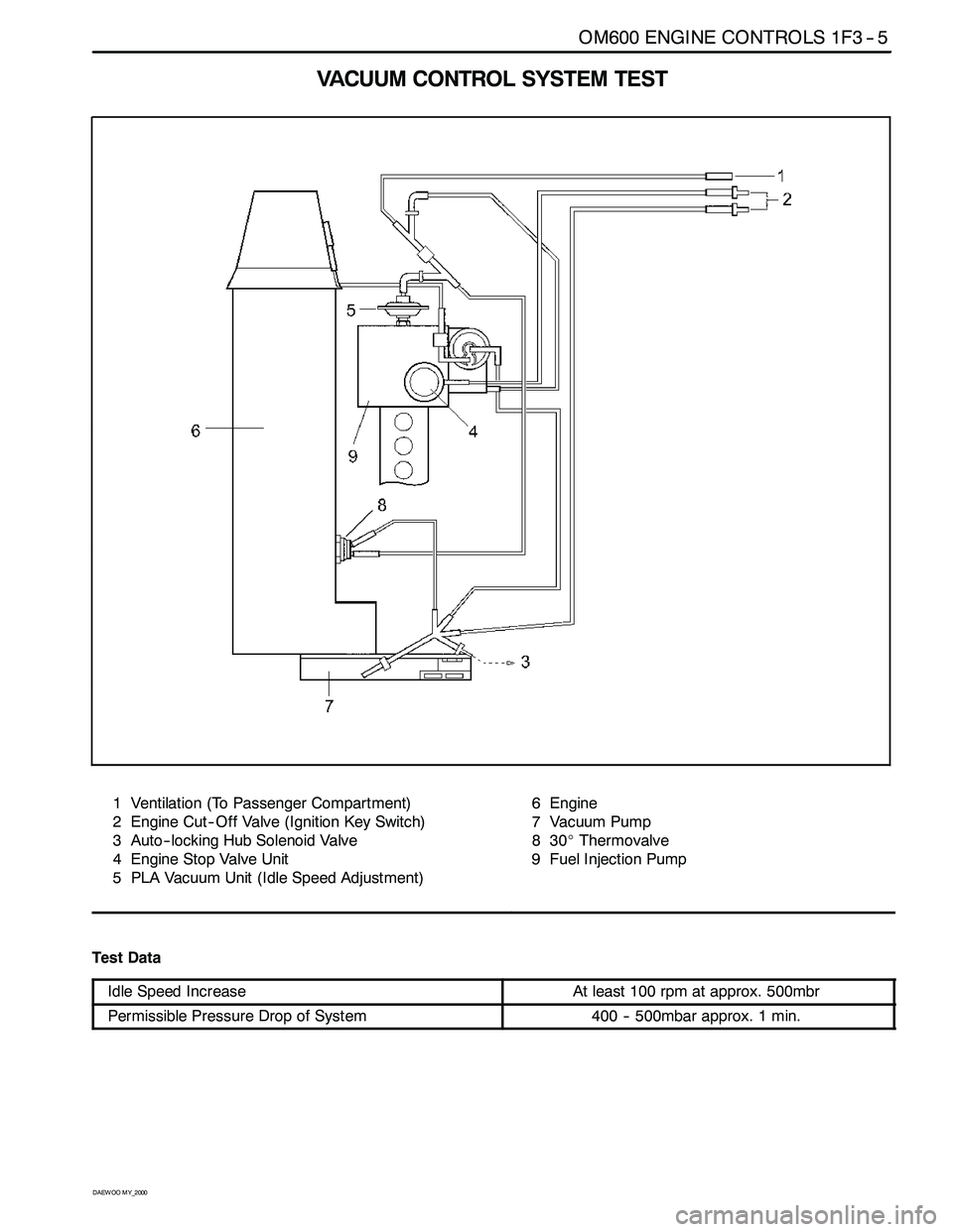
VACUUM CONTROLSYSTEM TEST
1 Ventilation (To Passenger Compartment)
2 Engine Cut -- Off Valve (Ignition Key Switch)
3 Auto-- locking Hub Solenoid Valve
4 Engine Stop Valve Unit
5 PLA Vacuum Unit (Idle Speed Adjustment)6Engine
7 Vacuum Pump
830_Thermovalve
9 Fuel Injection Pump
Test Data
Idle Speed IncreaseAt least 100 rpm at approx. 500mbr
Permissible Pressure Drop of System400 -- 500mbar approx. 1 min.
Page 809 of 2053
1F3 -- 6 OM600 ENGINE CONTROLS
D AEW OO M Y_2000
Tools Required
001 589 73 21 00 Vacuum Pump
201 589 13 21 00 Vacuum Tester
667 589 00 21 00 TDC pulse generator
Commercial Tools
Digital testere.g. Bosch MOT 001.03
Sun DIT 9000
Temperature measuring instrument with test probe
WB24e.g. Ahlborn, Therm 2263 -- 2
Eichenfeldstrabe 1 -- 3
D-- 8150 Holzkirchen
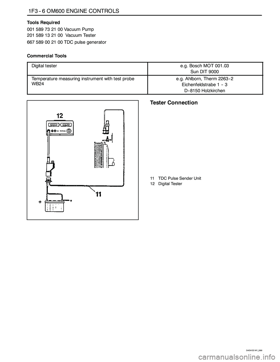
Tester Connection
11 TDC Pulse Sender Unit
12 Digital Tester
Page 810 of 2053
OM600 ENGINE CONTROLS 1F3 -- 7
D AEW OO M Y_2000
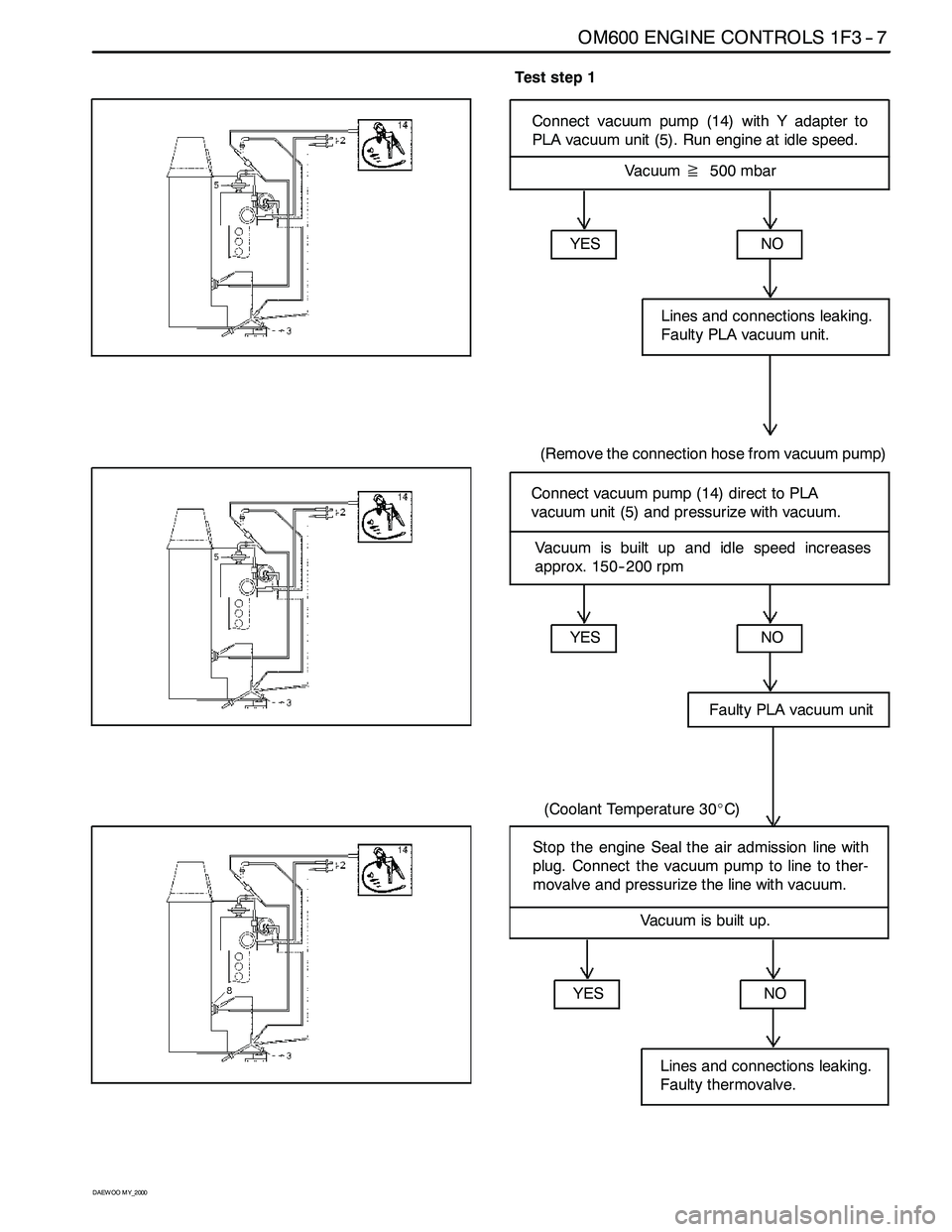
Test step 1
Connect vacuum pump (14) with Y adapter to
PLA vacuum unit (5). Run engine at idle speed.
Vacuum≧500 mbar
YES
NO
Faulty PLA vacuum unit
(Coolant Temperature 30_C)
Connect vacuum pump (14) direct to PLA
vacuum unit (5) and pressurize with vacuum.
YES
NO
Lines and connections leaking.
Faulty PLA vacuum unit.
(Remove the connection hose from vacuum pump)
Vacuum is built up and idle speed increases
approx. 150-- 200 rpm
YESNO
Lines and connections leaking.
Faulty thermovalve.
Stop the engine Seal the air admission line with
plug. Connect the vacuum pump to line to ther-
movalve and pressurize the line with vacuum.
Vacuum is built up.
Page 811 of 2053

1F3 -- 8 OM600 ENGINE CONTROLS
D AEW OO M Y_2000
Detach line downstream of air admission filter
(13).
Vacuum drops
YES
NO
Faulty filter with restriction.
Fit the line onto air admission filter. Built up vacu-
um with vacuum pump. Detach the plug from air
admission line.
YES
NO
Faulty thermovalve
Vacuum drops
Go to test step 2
Page 812 of 2053
OM600 ENGINE CONTROLS 1F3 -- 9
D AEW OO M Y_2000
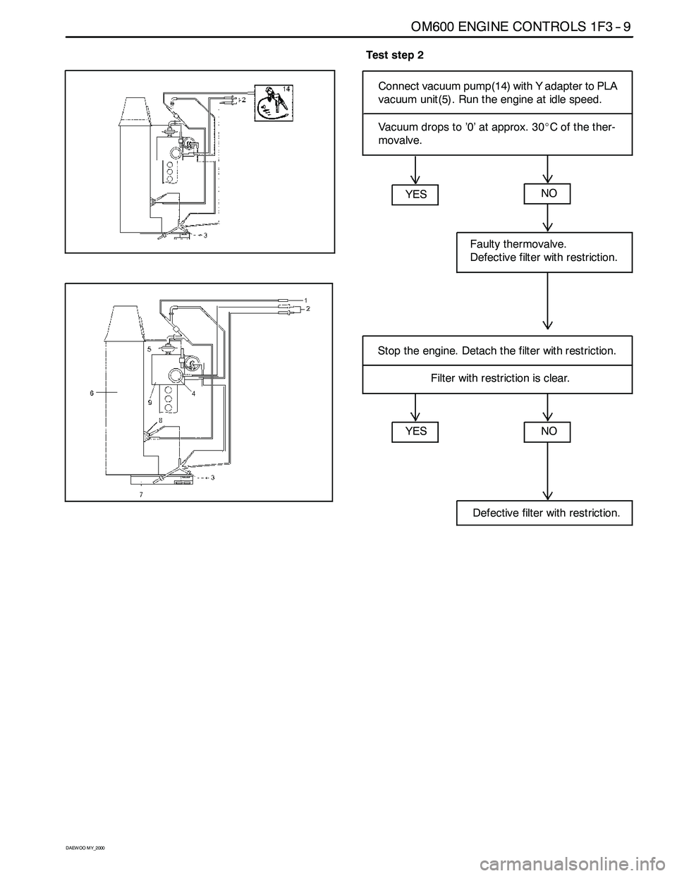
Test step 2
Connect vacuum pump(14) with Y adapter to PLA
vacuum unit(5). Run the engine at idle speed.
Vacuum drops to ’0’ at approx. 30_C of the ther-
movalve.
YES
NO
Defective filter with restriction.
Stop the engine. Detach the filter with restriction.
YES
NO
Faulty thermovalve.
Defective filter with restriction.
Filter with restriction is clear.
Page 821 of 2053
SSANGYONG MY2002
2B-2 WHEEL ALIGNMENT
FOUR WHEEL ALIGNMENT
The first responsibility of engineering is to design safe
steering and suspension systems. Each component
must be strong enough to withstand and absorb extreme
punishment. Both the steering system and the front
and the rear suspension must function geometrically
with the body mass.
The steering and the suspension systems require that
the front wheels self-return and that the tire rolling effor t
and the road friction be held to a negligible force in
order to allow the customer to direct the vehicle with
the least effort and the most comfort.
A complete wheel alignment check should include mea-
surements of the rear toe and camber.
Four-wheel alignment assures that all four wheels will
be running in precisely the same direction.
When the vehicle is geometrically aligned, fuel economy
and tire life are at their peak, and steering and perfor
mance are maximized.
TOE-IN
Toe-in is the turning in of the tires, while toe-out is the
turning out of the tires from the geometric centerline or
thrust line. The toe ensures parallel rolling of the wheels.
The toe serves to offset the small deflections of the
wheel support system which occur when the vehicle is
rolling forward. The specified toe angle is the setting
which achieves 0 degrees of toe when the vehicle is
moving.
Incorrect toe-in or toe-out will cause tire wear and re
duced fuel economy. As the individual steering and
sus-pension components wear from vehicle mileage,
additional toe will be needed to compensate for the
wear.
Always correct the toe dimension last.
CASTER
Caster is the tilting of the uppermost point of the steering
axis either forward or backward from the vertical when
viewed from the side of the vehicle. A backward tilt is
positive, and a forward tilt is negative. Caster influences
directional control of the steering but does not affect
tire wear. Weak springs or overloading a vehicle will
affect caster. One wheel with more positive caster will
pull toward the center of the car. This condition will
cause the car to move or lean toward the side with the
least amount of positive caster. Caster is measured in
degrees.
CAMBER
Camber is the tilting of the top of the tire from the
vertical when viewed from the front of the vehicle. When
the tires tilt outward, the camber is positive. When the
tires tilt inward, the camber is negative. The camber
angle is measured in degrees from the vertical. Camber
in-fluences both directional control and tire wear.
If the vehicle has too much positive camber, the outside
shoulder of the tire will wear. If the vehicle has too
much negative camber, the inside shoulder of the tire
will wear.
DESCRIPTION AND OPERATION