roof SSANGYONG KORANDO 1997 Service Repair Manual
[x] Cancel search | Manufacturer: SSANGYONG, Model Year: 1997, Model line: KORANDO, Model: SSANGYONG KORANDO 1997Pages: 2053, PDF Size: 88.33 MB
Page 962 of 2053

SSANGYONG MY2002
4E-2 REAR BRAKES
DESCRIPTION AND OPERATION
DRUM BRAKE
This drum brake assembly is a leading/trailing shoe
design.
Both brake shoes are held against the wheel cylinder
pistons by the lower return spring and the fixed anchor
plate near the lower return spring. When the brakes
are applied, the wheel cylinder pistons move both
shoes out to contact the drum. With forward wheel
rotation, the forward brake shoe will wrap into the drum
and become selt-energized. With reverse wheel
rotation, brake shoes is transferred to the anchor plate
through the braking plate to the axle flange.
Adjustment is automatic and occurs on any service
brake application. Do not switch the position of shoes
that have been in service, as this may render the self-
adjustment feature inoperative and result in increased
pedal travel.
The brake drum must have high abrasion resistance,
heatproof, high stiffness, fatigue stiffness and strength
enough not to make any deformation. The temperature
of the drum surface comes up to 500 - 700 °C on brake
operation by the friction with the lining. When the
temperature of the drum surface continues to keep
high, the friction coefficient goes down and the ‘fade
development’ occurs. When the brake is applied often
on the hill, any accident may be occur.
YAD4C010
Wheel Cylinder
Both wheel cylinder diameters are same in order to
balance the friction forces of both shoes.
The hydraulic pressure from the master cylinder is
provided to the wheel cylinder and the piston in the
wheel cylinder allows to push both shoes toward the
drum resulted in generating the braking force.
Brake Lining
The brake lining is installed with the brake shoe and
pushed toward the drum for applying the brake pedal.
Thus, lining must have high-heat tolerance, abrasion
resistance and high friction coefficient.
Brake Lining and Drum Clearance Automatic
Control System
If the lining’s wear is excessive, the piston moves to
long distance and the pedal travel increases. The
clearance between the drum and the brake lining
should be adjusted.
Generally the drum brake must be adjusted regularly
and thus the clearance automatic control system
enables to adjust the clearance between the brake
lining and the drum resulting from brake lining wear.
YAD4C020
1 Cylinder Housing
2 Boot
3 Spring
4 Piston Cup
5 Piston
6 Air Bleeder1 Cylinder Housing
2 Boot
3 Spring
4 Piston Cup
5 Piston
6 Air Bleeder
Page 1652 of 2053

SECTION 9A
BODY WIRING SYSTEM
CAUTION: Disconnect the negative battery cable before removing or installing any electrical unit or when a
tool or equipment could easily come in contact with exposed electrical terminals. Disconnecting this cable
will help prevent personal injury and damage to the vehicle. The ignition must also be in LOCK unless
otherwise noted.
TABLE OF CONTENTS
General Description.............................................9A-2
Wire Color Chart..................................................9A-2
Engine Room Fuse & Relay Box......................... 9A-3
Usage of Fuse in Engine Room Fuse Box.............9A-5
Passenger Room Fuse Box..................................9A-6
Usage of Fuse in Engine Room Fuse Box.............9A-7
Schematic and Routing Diagrams.......................9A-8
Engine Room Fuse & Relay Circuit.......................9A-8
Wiring Harness & Connector &
Ground Location................................................. 9A-11
W/H Engine Room.............................................9A-11W/H Main..........................................................9A-12
W/H Main (Floor)............................................... 9A-14
W/H Roof..........................................................9A-15
W/H Seat Heater................................................9A-16
W/H Door..........................................................9A-17
W/H Tail Gate....................................................9A-18
W/H Air-Conditioner...........................................9A-19
W/H Engine Control (Gasoline)...........................9A-20
W/H Pre-Heating (Diesel)...................................9A-21
W/H Transmission..............................................9A-22
Page 1666 of 2053

BODY WIRING SYSTEM 9A-15
SSANGYONG MY2002
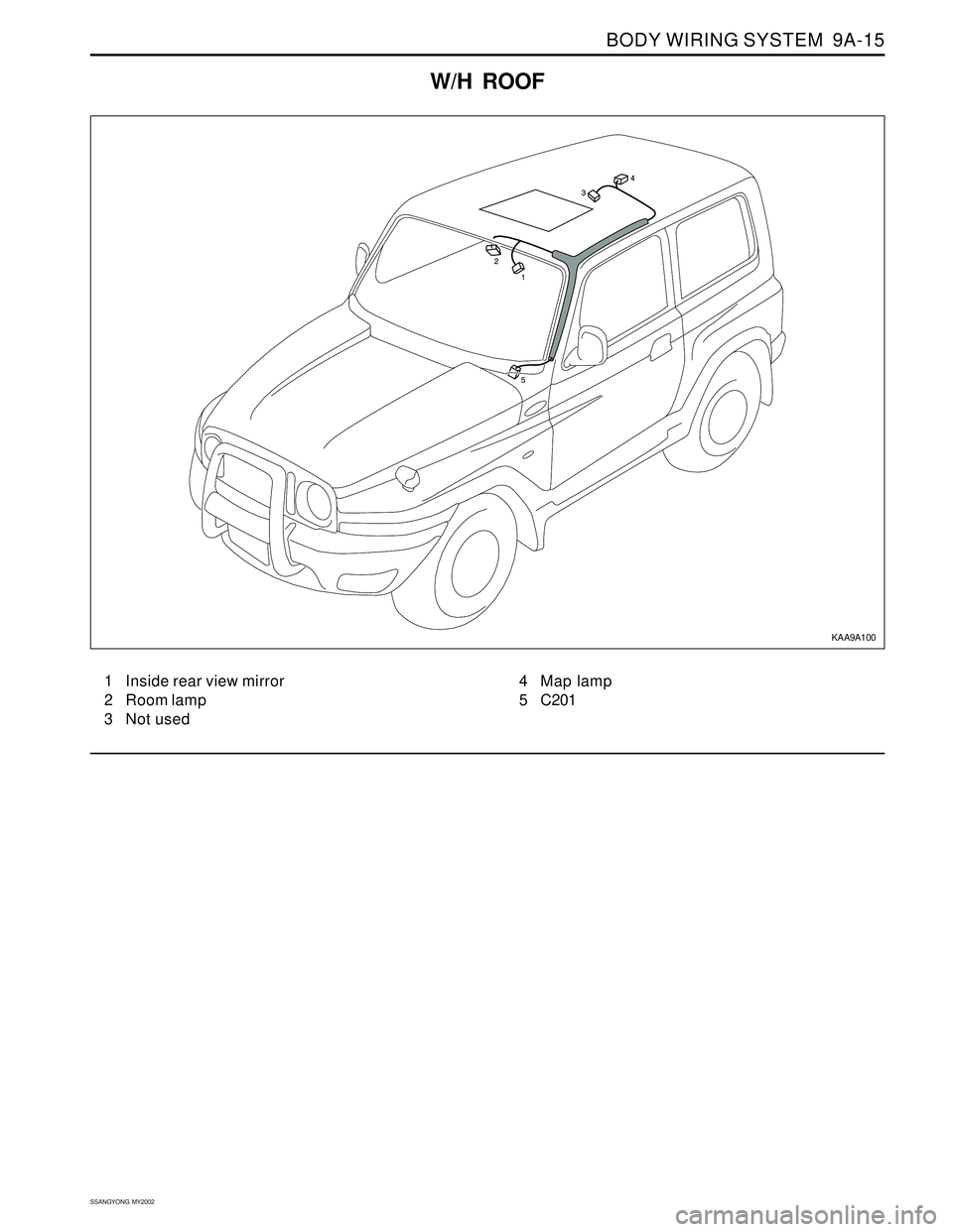
W/H ROOF
1 Inside rear view mirror
2 Room lamp
3 Not used4 Map lamp
5 C201
KAA9A100
Page 1754 of 2053

INTERIOR TRIM 9G-5
SSANGYONG MY2002
EF
KAA9G060
KAA9G050
A-PILLAR TRIM PANEL
Removal and Installation Procedure
1. Remove the roof assist handle with the screws.
2. Remove the A-pillar trim panel.
3. Installation should follow the removal procedure
in the reverse order. 6. Disconnect the electrical connector.
7. Remove the door trim panel.
8. Installation should follow the removal procedure
in the reverse order.
KAA9G080
KAA9G070
3. Remove the upper quarter trim panel.
4. Installation should follow the removal procedure
in the reverse order.
UPPER QUARTER TRIM PANEL
Removal and Installation Procedure
1. Remove the roof assist handle with the screws.
2. Remove the seat belt anchor with the bolt.
Installation Notice
•Dissimilar metals in direct contact with each
other may corrode rapidly. Make sure to use
the correct fasteners to prevent premature
corrosion.
Tightening Torque 45 Nm (33 lb-ft)
Page 1755 of 2053

SSANGYONG MY2002
9G-6 INTERIOR TRIM
� �
�
y y
y
KAA9G100
KAA9G090
2. Remove the armrest. Refer to Section 9H “SEATS”.
3. Remove the ashtray and compartment lamp from
lower quarter trim panel.
4. Remove the roof rear trim and back panel cover.
LOWER QUARTER TRIM PANEL
Removal and Installation Procedure
1. Lift up the rear seat from the floor.
KAA9G120
KAA9G110
COWL SIDE TRIM PANEL
Removal and Installation Procedure
1. Remove the cowl side trim panel. Refer to front
rocker trim panel in this section.
2. Remove the cowl side trim panel with the screws.
3. Installation should follow the removal procedure
in the reverse order. 5. Remove the lower quarter trim panel with the
screws.
6. Installation should follow the removal procedure
in the reverse order.
Page 1796 of 2053

Description and Operation..................................9M-2
Emblems and Lettering.......................................9M-2
Mud Guards.......................................................9M-2
Components Locator ...........................................9M-3
Exterior Trim.......................................................9M-3
Repair Instructions...............................................9M-4
On-Vehicle Service Unit Repair...............................9M-4
B-Pillar Molding..................................................9M-4
B-Pillar Cover......................................................9M-4
SECTION 9M
EXTERIOR TRIM
CAUTION: Disconnect the negative battery cable before removing or installing any electrical unit or when a
tool or equipment could easily come in contact with exposed electrical terminals. Disconnecting this cable
will help prevent personal injury and damage to the vehicle. The ignition must also be in LOCK unless
otherwise noted.
TABLE OF CONTENTS
Air Extractor Grille...............................................9M-4
Door Molding......................................................9M-5
Front Wheel Molding...........................................9M-5
Rear Wheel Molding...........................................9M-5
Side Step...........................................................9M-6
C-Pillar Cover......................................................9M-6
Roof Molding......................................................9M-6
Specifications......................................................9M-7
Fastener Tightening Specifications......................9M-7
Page 1798 of 2053

EXTERIOR TRIM 9M-3
SSANGYONG MY2002
COMPONENTS LOCATOR
EXTERIOR TRIM
1 Rivet
2 B Pillar Cover
3 Air Extractor Grill
4 Air Extractor Grill Tape
5 Door Molding
6 Front Wheel Arch Molding
7 Rear Wheel Arch Molding
8 Side Step
9 Side Step Upper Cover
10 Bolt
11 Wheel Arch Clip12 Garnish Clip
13 Garnish Clip
14 Door Molding Clip
15 Door Molding Clip
16 Clip
17 “C” Pillar Cover
18 Clip
19 Tailgate Garnish
20 Roof Molding
21 Roof Molding Endcap
22 Clip
KAA9M010
Page 1801 of 2053

SSANGYONG MY2002
9M-6 EXTERIOR TRIM
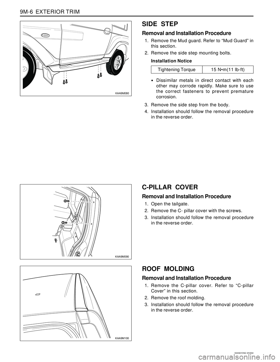
KAA9M090
KAA9M100
C-PILLAR COVER
Removal and Installation Procedure
1. Open the tailgate.
2. Remove the C- pillar cover with the screws.
3. Installation should follow the removal procedure
in the reverse order. 3. Remove the side step from the body.
4. Installation should follow the removal procedure
in the reverse order.
ROOF MOLDING
Removal and Installation Procedure
1. Remove the C-pillar cover. Refer to “C-pillar
Cover” in this section.
2. Remove the roof molding.
3. Installation should follow the removal procedure
in the reverse order.
SIDE STEP
Removal and Installation Procedure
1. Remove the Mud guard. Refer to “Mud Guard” in
this section.
2. Remove the side step mounting bolts.
Installation Notice
Dissimilar metals in direct contact with each
other may corrode rapidly. Make sure to use
the correct fasteners to prevent premature
corrosion.
KAA9M080
Tightening Torque 15 Nm(11 lb-ft)
Page 1811 of 2053

FRAME AND UNDERBODY 9N-9
SSANGYONG MY2002
GENERAL DESCRIPTION AND SYSTEM OPERATION
GENERAL BODY CONSTRUCTION
This vehicle is constructed with a unitized body which
in-corporates integral front and rear frame side rails.
The front suspension lower control arms are bolted to
and retained by supports, one each on the right and
left sides. The front suspension lower control arm
supports are attached to the underbody with three bolts
at two locations. The engine is bolted to the integral
front side rails. The suspension strut towers must be
dimensionally correct in relation to the remainder of
the underbody in order to maintain specified
suspension strut and caster/camber angles.
Since the individual underbody parts contribute directly
to the overall strength of the body, it is essential to
observe proper welding techniques during servicerepair operations. The underbody parts should be
properly sealed and rustproofed whenever body repair
operations destroy or damage the original sealing and
rustproofing. When rustproofing critical underbody
parts, use a good-quality type of air-dry primer, such
as a corrosion-resistant chromate or an equivalent
material. Combination-type primer/surfacers are not
recommended.
ENGINE UNDER COVERS
The engine under covers are molded pieces of plastic
that serve as shields for the underside of the engine.
The covers help protect the engine from small rocks,
gravel and other objects that would otherwise come
into contact with the engine during normal driving
conditions.
Page 1812 of 2053

SSANGYONG MY2002
9O-6 BUMPERS AND FASCIAS
KAA9O070
REAR BUMPER IMPACT BAR
Removal and Installation Procedure
1. Remove the rear bumper fascia. Refer to Rear
Bumper Fascia in this section.
2. Remove the rear bumper impact bar.
3. Installation should follow the removal procedure
in the reverse order.
ROOF MOLDING
Removal and Installation Procedure
1. Remove the C-pillar cover. Refer to “C-pillar
Cover” in this section.
2. Remove the roof molding
3. Installation should follow the removal procedure
in the reverse order.