check engine SSANGYONG KORANDO 1997 Service Repair Manual
[x] Cancel search | Manufacturer: SSANGYONG, Model Year: 1997, Model line: KORANDO, Model: SSANGYONG KORANDO 1997Pages: 2053, PDF Size: 88.33 MB
Page 8 of 2053
0B -- 8 GENERAL INFORMATION
D AEW OO M Y_2000
MAINTENANCE AND REPAIR
MAINTENANCE AND
LUBRICATION
NORMAL VEHICLE USE
The maintenance instructions contained in the mainte-
nance schedule are based on the assumption that the
vehicle will be used for the following reasons:
DTo carry passengers and cargo within the limitation of
the tire inflation prassure. Refer to “Tire and Wheel” in
section 2E.
DTo be driven on reasonable road surfaces and within
legal operating limits.
EXPLANATION OF SCHEDULED
MAINTENANCE SERVICES
The services listed in the maintenance schedule are fur-
ther explained below. When the following maintenance
services are performed, make sure all the parts are re-
placed and all the necessary repairs are done before
driving the vehicle. Always use the proper fluid and lubri-
cants.
Engine Oil and Oil Filter Change
Always use above the API SH grade or recommended
engine oil.
Engine Oil Viscosity
Engine oil viscosity (thickness) has an effect on fuel
economy and cold weather operation. Lower viscosity
engine oils can provide better fuel economy and cold
weather performance; however, higher temperature
weather conditions require higher viscosity engine oils
for satisfactory lubrication. Using oils of any viscosity
other than those viscosities recommended could result
in engine damage.
Cooling System Service
Drain, flush and refill the system with new coolant. Refer
to “Recommended Fluids And Lubricants“ in this sec-
tion.
Air Cleaner Element Replacement
Clean the air cleaner element every.
DGasoline Engine : 15,000km (10,000 miles)
DDiesel Engine : 10,000km (6,000 miles)
Replace the air cleaner element every .
DGasoline Engine : 60,000km (36,000 miles)DDiesel Engine : 30,000km (18,000 miles)
Replace the air cleaner more often under dusty condi-
tions.
Fuel Filter Replacement
Replace the engine fuel filter every.
DGasoline Engine : 60,000km (36,000 miles)
DDiesel Engine : 45,000km (24,000 miles)
Spark Plug Replacement
Replace spark plugs with same type.
DType : BOSCH : F8DC4
BERU : 14F-- 8DU4
Champion : C11YCC
DGap : 0.8±0.1 mm
Spark Plug Wire Replacement
Clean wires and inspect them for burns, cracks or other
damage. Check the wire boot fit at the Distributor and at
the spark plugs. Replace the wires as needed.
Brake System Service
Check the disc brake pads or the drum brake linings.
Check the pad and the lining thickness carefully.
Tire and Wheel Inspection and Rotation
Check the tires for abnormal wear or damage. To equal-
ize wear and obtain maximum tire life, rotate the tires. If
irregular or premature wear exists, check the wheel
alignment and check for damaged wheels. While the
tires and wheels are removed, inspect the brakes.
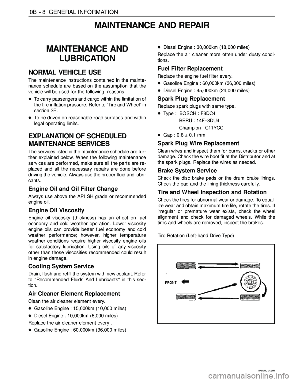
Tire Rotation (Left-hand Drive Type)
Page 13 of 2053
GENERAL INFORMATION 0B -- 13
D AEW OO M Y_2000
OWNER INSPECTIONS AND SERVICES
WHILE OPERATING THE VEHICLE
Horn Operation
Blow the horn occasionally to make sure it works. Check
all the button locations.
Brake System Operation
Be alert for abnormal sounds, increased brake pedal
travel or repeated puling to one side when braking. Also,
if the brake warning light goes on, or flashes, something
may be wrong with part of the brake system.
Exhaust System Operation
Be alert to any changes inthe sound of the system or
the smell of the fumes. These are signs that the system
may be leaking or overheating. Have the system in-
spected and repaired immediately.
Tires, Wheels and Alignment Operation
Be alert to any vibration of the steering wheel or the
seats at normal highway speeds. This may mean a
wheel needs to be balanced. Also, a pull right or left on a
straight, level road may show the need for a tire pres-
sure adjustment or a wheel alignment.
Steering System Operation
Be alert to changes in the steering action. An inspection
is needed when the steering wheel is hard to turn or has
too much free play, or is unusual sounds are noticed
when turning or parking.
Headlight Aim
Take note of the light pattern occasionally. Adjust the
headlights if the beams seem improperly aimed.
AT EACH FUEL FILL
A fluid loss in any (except windshield washer) system
may indicate a problem. Have the system inspected and
repaired immediately.
Engine Oil Level
Check the oil level and add oil if necessary. The best
time to check the engine oil level is when the oil is warm.
1. After stopping the engine, wait a few minutes for the
oil to drain back to the oil pan.
2. Pull out the oil level indicator (dip stick).
3. Wipe it clean, and push the oil level indicator back
down all the way.
4. Pull out the oil level indicator and look at the oil level
on it.
5. Add oil, if needed, to keep the oil level above the low-
er mark. Avoid overfilling theengine, since this may
cause engine damage.
6. Push the indicator all the way back down into the en-
gine after taking the reading.If you check the oil level when the oil is cold, do not run
the engine first. The cold oil will not drain back to the pan
fast enough to give a true oil level reading.
Engine Coolant Level and Condition
Check the coolant level in the coolant reservoir tank and
add coolant if necessary. Inspect the coolant. Replace
dirty or rusty coolant.
Windshield Washer Fluid Level
Check the washer fluid level in the reservoir. Add fluid if
necessary.
AT LEAST TWICE A MONTH
Tire And Wheel Inspection and Pressure
Check
Check the tire for abnormal wear or damage. Also check
for damaged wheels. Check the tire pressure when the
tires are cold ( check the spare also, unless it is a stow-
away). Maintain the recommended pressures. Refer to
“Tire and Wheel” is in section 0B.
AT LEAST MONTHLY
Light Operation
Check the operation of the license plate light, the head-
lights (including the high beams), the parking lights, the
fog lights, the taillight, the brake lights, the turn signals,
the backup lights and the hazard warning flasher.
Fluid Leak Check
Periodically inspect the surface beneath the vehicle for
water, oil, fuel or other fluids, after the vehicle has been
parked for a while. Water dripping from the air condition-
ing system after use is normal. If you notice fuel leaks or
fumes, find the cause and correct it at once.
AT LEAST TWICE A YEAR
Power Steering System Reservoir Level
Check the power steering fluid level. Keep the power
steering fluid at the proper level. Refer to Section 6A,
Power Steering System.
Brake Master Cylinder Reservoir Level
Check the fluid and keep it at the proper level. A low fluid
level can indicate worn disc brake pads which may need
to be serviced. Check the breather hole in the reservoir
cover to be free from dirt and check for an open pas-
sage.
Weather- Strip Lubrication
Apply a thin film silicone grease using a clean cloth.
Page 14 of 2053
0B -- 14 GENERAL INFORMATION
D AEW OO M Y_2000
EACH TIME THE OIL IS CHANGED
Brake System Inspection
This inspection should be done when the wheels are re-
moved for rotation. Inspect the lines and the hoses for
proper hookup, binding, leaks, cracks, chafing, etc. In-
spect the disc brake pads for wear. Inspect the rotors for
surface condition. Inspect other brake parts, the parking
brake, etc., at the same time. Inspect the brakes more
often if habit or conditions result in frequent braking.
Steering, Suspension and Front Drive Axle
Boot And Seal Inspection
Inspect the front and rear suspension and the steering
system for damaged, loose or missing parts, signs of
wear or lack of lubrication. Inspect the power steering
line and the hoses for proper hookup, binding, leaks,
cracks, chafing, etc. Clean and inspect the drive axle
boot and seals for damage, tears or leakage. Replace
the seals if necessary.
Exhaust System Inspection
Inspect the complete system (including the catalytic
converter if equipped). Inspect the body near the ex-
haust system. Look for broken, damaged, missing, or
out -- of -- position parts as well as open seams, holes,
loose connections, or other conditions which could
cause heat buildup in the floor pan or could let exhaust
fumes seep into the trunk or passenger compartment.
Throttle Linkage Inspection
Inspect the throttle linkage for interference or binding,
damaged, or missing parts. Lubricate all linkage joints
and throttle cable joints, the intermediate throttle shaft
bearing, the return spring at throttle valve assembly, and
the accelerator pedal sliding face with suitable grease.
Check the throttle cable for free movements.
Engine Drive Belts
Inspect all belts for cracks, fraying, wear and proper ten-
sion. Adjust or replace the belts as needed.
Hood Latch Operation
When opening the hood, note the operation of the sec-
ondary latch. It should keep the hood from opening all
the way when the primary latch is released. The hood
must close firmly.
AT LEAST ANNUALLY
Lap and Shoulder Belts Condition and Operation
Inspect the belt system including: the webbing, the
buckles, the latch plates, the retractor, the guide loops
and the anchors.
Movable Head Restraint Operation
On vehicles with movable head restraints, the restraints
must stay in the desired position.
Spare Tire and Jack Storage
Be alert to rattles in the rear of the vehicle. The spare
tire, all the jacking equipment, and the tools must be se-
curely stowed at all times. Oil the jack ratchet or the
screw mechanism after each use.
Key Lock Service
Lubricate the key lock cylinder.
Body Lubrication Service
Lubricate all the body door hinges including the hood,
the fuel door, the rear compartment hinges and the
latches, the glove box and the console doors, and any
folding seat hardware.
Underbody Flushing
Flushing the underbody will remove any corrosive mate-
rials used for ice and snow removal and dust control. At
least every spring clean the underbody. First, loosen the
sediment packed in closed areas of the vehicle. Then
flush the underbody with plain water.
Engine Cooling System
Inspect the coolant and freeze protection fluid. If the
fluid is dirty or rusty, drain, flush and refill the engine
cooling system with new coolant. Keep the coolant at
the proper mixture in order to ensure proper freeze
protection, corrosion protection and engine operating
temperature. Inspect the hoses. Replace the cracked,
swollen, or deteriorated hoses. Tighten the clamps.
Clean the outside of the radiator and the air conditioning
condenser. Wash the filler cap and the neck. Pressure
test the cooling system and the cap in order to help en-
sure proper operation.
Page 26 of 2053
1A1 -- 6 GENERAL ENGINE INFORMATION
D AEW OO M Y_2000
DIAGNOSIS
OIL LEAK DIAGNOSIS
Most fluid oil leaks are easily located and repaired by
visually finding the leak and replacing or repairing the
necessary parts. On some occasions a fluid leak may be
difficult to locate or repair. The following procedures may
help you in locating and repairing most leaks.
Finding the Leak
1. Identify the fluid. Determine whether it is engine oil,
automatic transmission fluid, power steering fluid,
etc.
2. Identify where the fluid is leaking from.
2.1 After running the vehicle at normal operating
temperature, park the vehicle over a large sheet
of paper.
2.2 Wait a few minutes.
2.3 You should be able to find the approximate loca-
tion of the leak by the drippings on the paper.
3. Visually check around the suspected component.
Check around all the gasket mating surfaces for
leaks. A mirror is useful for finding leaks in areas that
are hard to reach.
4. If the leak still cannot be found, it may be necessary
to clean the suspected area with a degreaser, steam
or spray solvent.
4.1 Clean the area well.
4.2 Dry the area.
4.3 Operate the vehicle for several miles at normal
operating temperature and varying speeds.
4.4 After operating the vehicle, visually check the
suspected component.
4.5 If you still cannot locate the leak, try using the
powder or black light and dye method.
Powder Method
1. Clean the suspected area.
2. Apply an aerosol-- type powder (such as foot powder)
to the suspected area.
3. Operate the vehicle under normal operating condi-
toins.
4. Visually inspect the suspected component. You
should be able to trace the leak path over the white
powder surface to the source.
Black Light and Dye Method
A dye and light kit is available for finding leaks, Refer to
the manufacturer ’s directions when using the kit.
1. Pour the specified amount of dye into the engine oil fill
tube.
2. Operate the vehicle normal operating conditions as
directed in the kit.
3. Direct the light toward the suspected area. The dyed
fluid willappear as a yellow path leading to the
source.
Repairing the Leak
Once the origin of the leak has been pinpointed and
traced back to its source, the cause of the leak must be
determined n order for it to be repaired properly. If a gas-
ket is replaced, but the sealing flange is bent, the new
gasket will not repair the leak. Thebent flange must be
repaired also. Before attempting to repair a leak, check
for the following conditions and correct them as they
may cause a leak.
Gaskets
DThe fluid level/pressure is too high.
DThe crankcase ventilation system is malfunctioning.
DThe fasteners are tightened improperly or the threads
are dirty or damaged.
DThe flanges or the sealing surface is warped.
DThere are scratches, burrs or other damage to the
sealing surface.
DThe gasket is damaged or worn.
DThere is cracking or porosity of the component.
DAn improper seal was used (where applicable).
Seals
DThe fluid level/pressure is too high.
DThe crankcase ventilation system is malfunctioning.
DThe seal bore is damaged (scratched, burred or
nicked).
DThe seal is damaged or worn.
DImproper installation is evident.
DThere are cracks in the components.
DThe shaft surface is scratched, nicked or damaged.
DA loose or worn bearing is causing excess seal wear.
Page 31 of 2053
GENERAL ENGINE INFORMATION 1A1 -- 11
D AEW OO M Y_2000
Leakage Test
1. Warm the engine up to normal operating tempera-
ture.
2. Disconnect the negative battery cable.
3. Remove the spark plugs.
4. Check the coolant level by opening the coolant
surge tank cap and replenish if insufficient.
5. Open the engine oil filler cap.
6. Connect the tester to air pressure line and adjust the
scale of tester.
7. Install the connecting hose to spark plug hole.
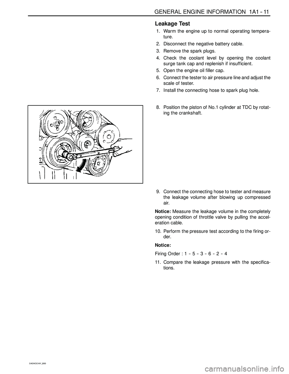
8. Position the piston of No.1 cylinder at TDC by rotat-
ing the crankshaft.
9. Connect the connecting hose to tester and measure
the leakage volume after blowing up compressed
air.
Notice:Measure the leakage volume in the completely
opening condition of throttle valve by pulling the accel-
eration cable.
10. Perform the pressure test according to the firing or-
der.
Notice:
FiringOrder:1--5--3--6--2--4
11. Compare the leakage pressure with the specifica-
tions.
Page 50 of 2053
1B1 -- 18 M162 ENGINE MECHANICAL
D AEW OO M Y_2000
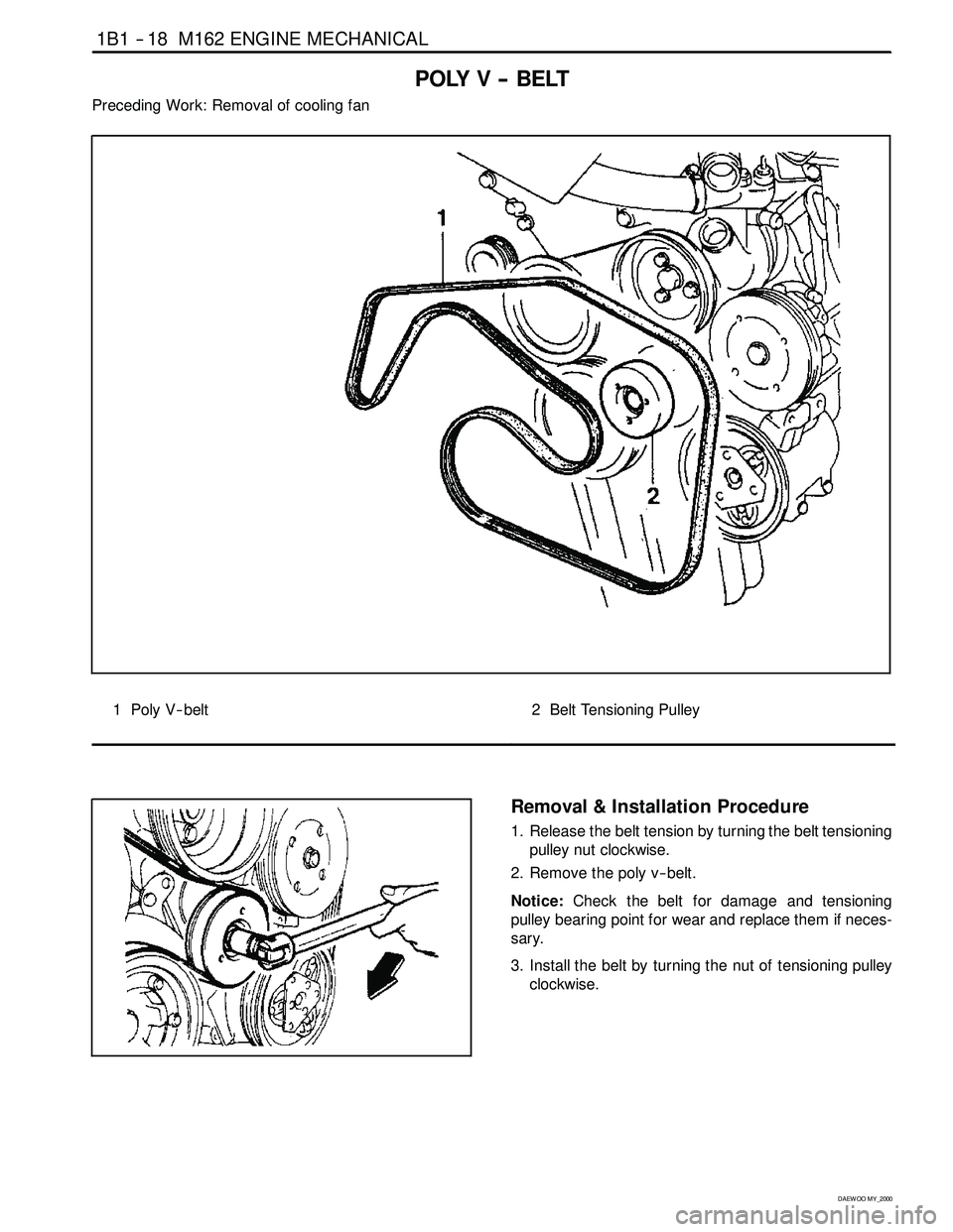
POLY V -- BELT
Preceding Work: Removal of cooling fan
1 Poly V-- belt2 Belt Tensioning Pulley
Removal & Installation Procedure
1. Release the belt tension by turning the belt tensioning
pulley nut clockwise.
2. Remove the poly v -- belt.
Notice:Check the belt for damage and tensioning
pulley bearing point for wear and replace them if neces-
sary.
3. Install the belt by turning the nut of tensioning pulley
clockwise.
Page 53 of 2053
M162 ENGINE MECHANICAL 1B1 -- 21
D AEW OO M Y_2000
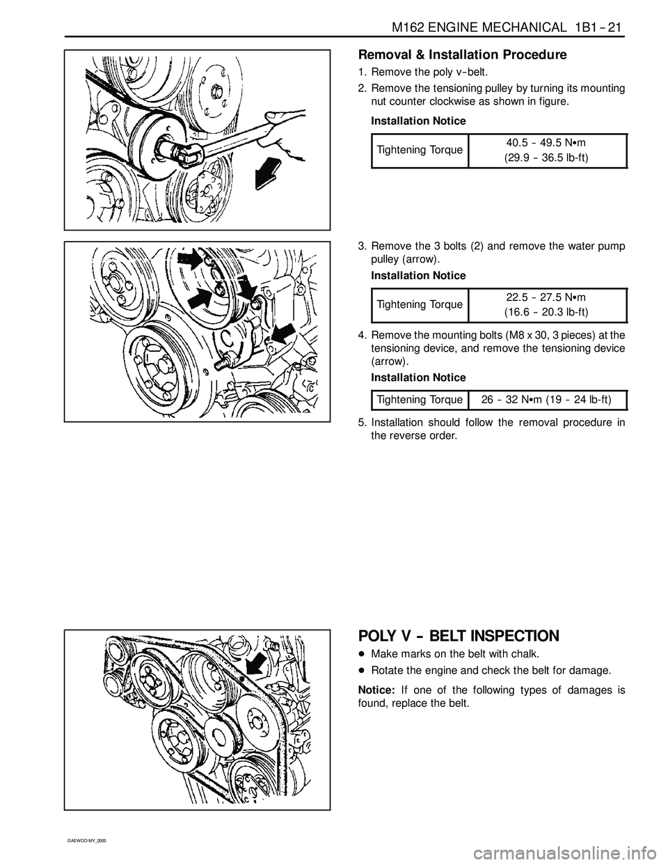
Removal & Installation Procedure
1. Remove the poly v -- belt.
2. Remove the tensioning pulley by turning its mounting
nut counter clockwise as shown in figure.
Installation Notice
Tightening Torque
40.5 -- 49.5 NSm
(29.9 -- 36.5 lb-ft)
3. Remove the 3 bolts (2) and remove the water pump
pulley (arrow).
Installation Notice
Tightening Torque
22.5 -- 27.5 NSm
(16.6 -- 20.3 lb-ft)
4. Remove the mounting bolts (M8 x 30, 3 pieces) at the
tensioning device, and remove the tensioning device
(arrow).
Installation Notice
Tightening Torque
26 -- 32 NSm (19 -- 24 lb-ft)
5. Installation should follow the removal procedure in
the reverse order.
POLY V -- BELT INSPECTION
DMake marks on the belt with chalk.
DRotate the engine and check the belt for damage.
Notice:If one of the following types of damages is
found, replace the belt.
Page 57 of 2053
M162 ENGINE MECHANICAL 1B1 -- 25
D AEW OO M Y_2000
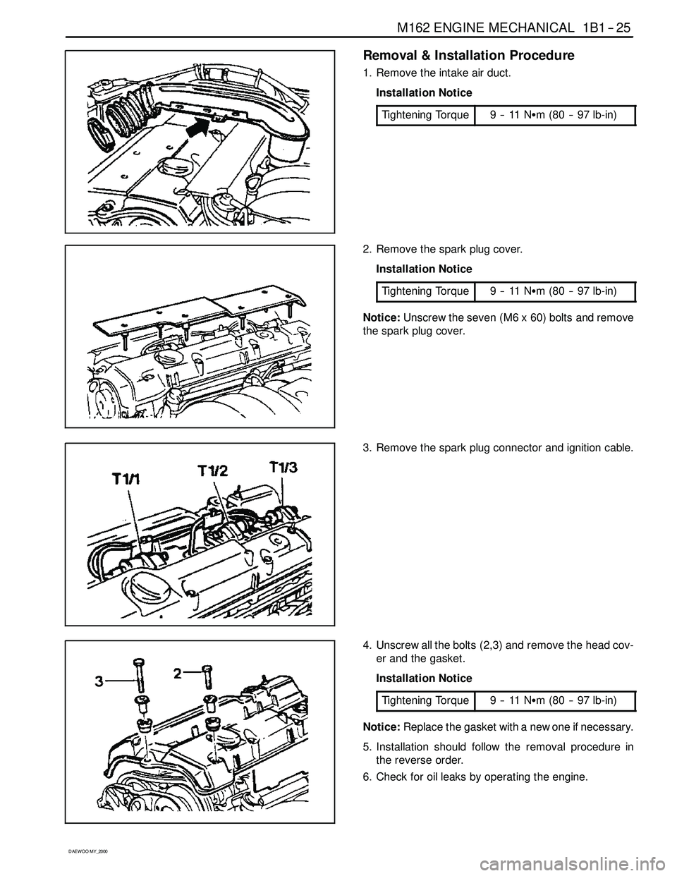
Removal & Installation Procedure
1. Remove the intake air duct.
Installation Notice
Tightening Torque
9--11NSm (80 -- 97 lb-in)
2. Remove the spark plug cover.
Installation Notice
Tightening Torque
9--11NSm (80 -- 97 lb-in)
Notice:Unscrew the seven (M6 x 60) bolts and remove
the spark plug cover.
3. Remove the spark plug connector and ignition cable.
4. Unscrew all the bolts (2,3) and remove the head cov-
er and the gasket.
Installation Notice
Tightening Torque
9--11NSm (80 -- 97 lb-in)
Notice:Replace the gasket with a new one if necessary.
5. Installation should follow the removal procedure in
the reverse order.
6. Check for oil leaks by operating the engine.
Page 62 of 2053
1B1 -- 30 M162 ENGINE MECHANICAL
D AEW OO M Y_2000
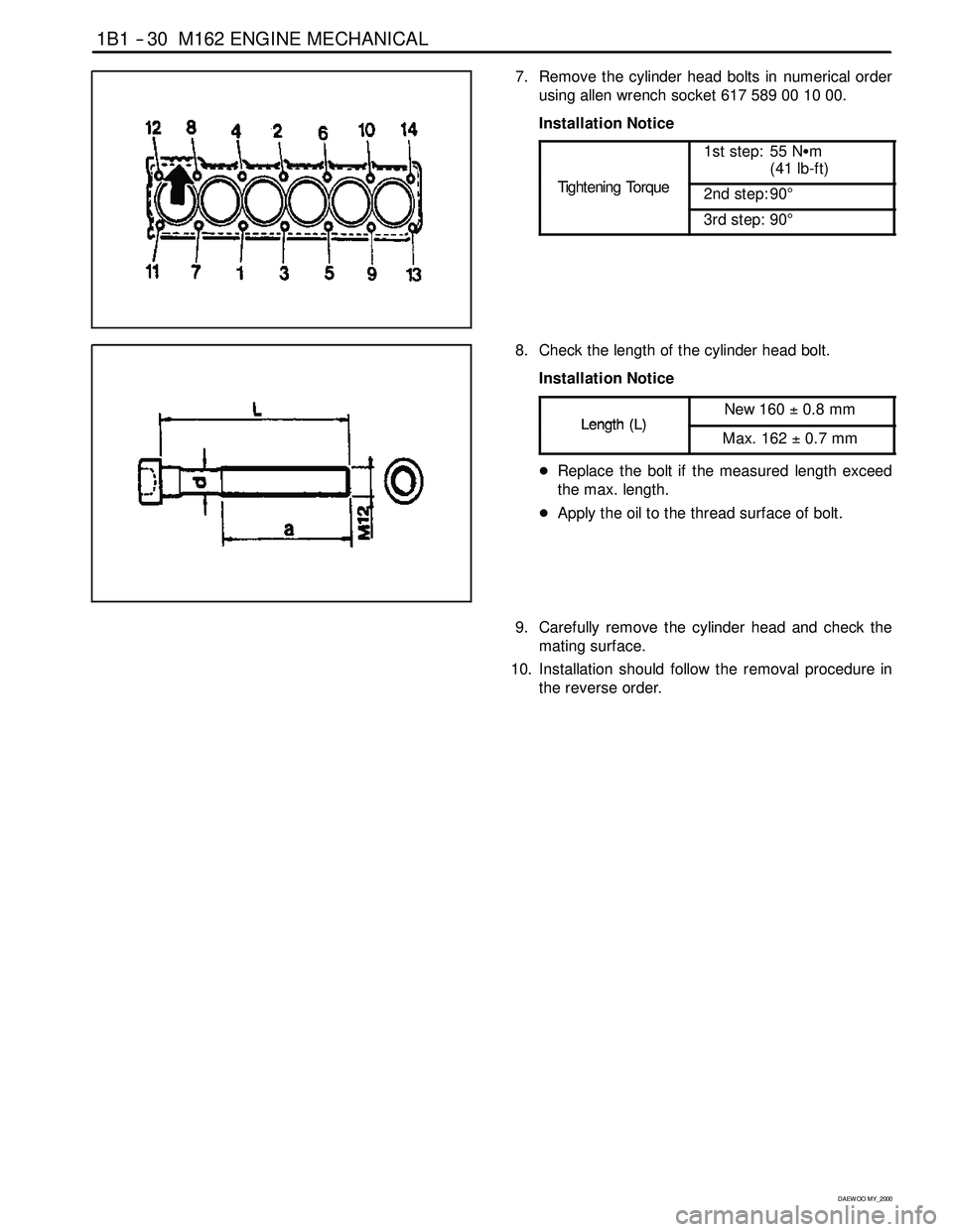
7. Remove the cylinder head bolts in numerical order
usingallenwrenchsocket617589001000.
Installation Notice
TihtiT
1st step: 55 NSm
(41 lb-ft)
Tightening Torque2nd step: 90°
3rd step: 90°
8. Check the length of the cylinder head bolt.
Installation Notice
Length(L)New 160±0.8 mmLength(L)Max. 162±0.7 mm
DReplace the bolt if the measured length exceed
the max. length.
DApply the oil to the thread surface of bolt.
9. Carefully remove the cylinder head and check the
mating surface.
10. Installation should follow the removal procedure in
the reverse order.
Page 64 of 2053
1B1 -- 32 M162 ENGINE MECHANICAL
D AEW OO M Y_2000
Removal & Installation Procedure
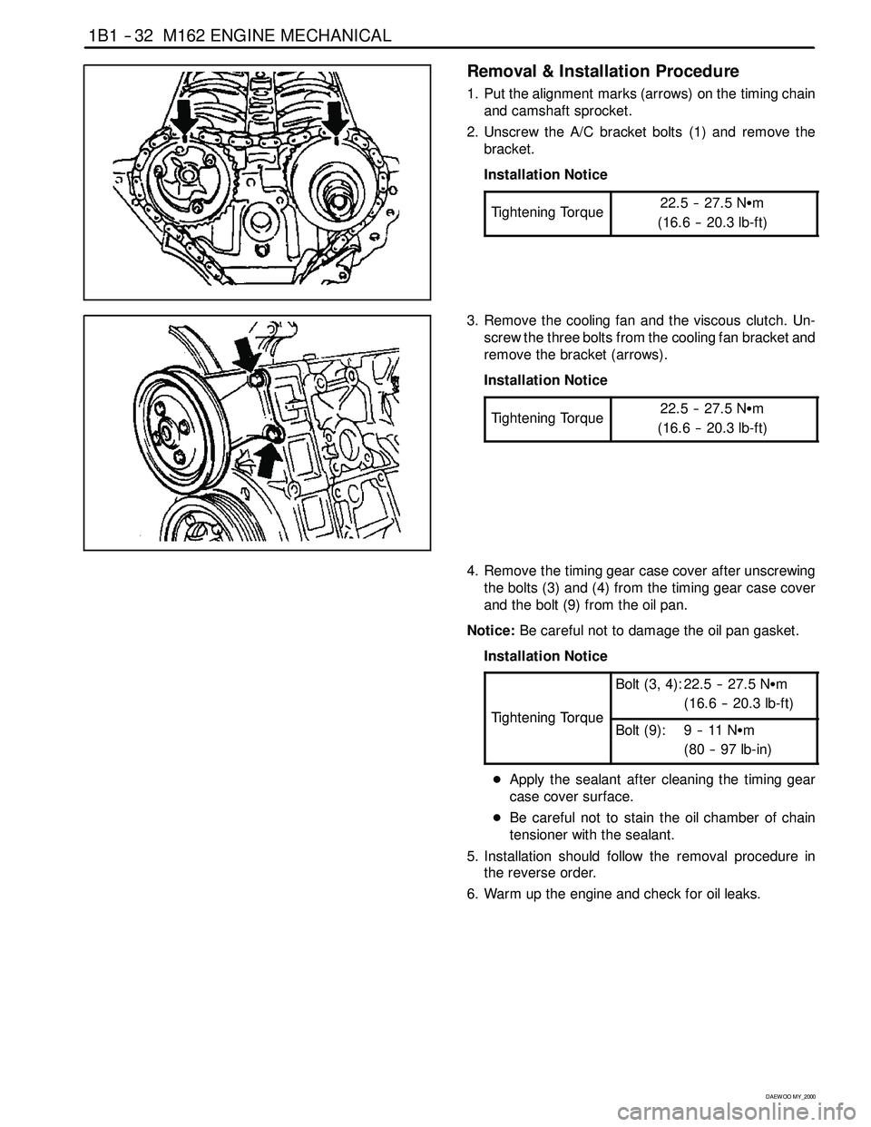
1. Put the alignment marks (arrows) on the timing chain
and camshaft sprocket.
2. Unscrew the A/C bracket bolts (1) and remove the
bracket.
Installation Notice
Tightening Torque
22.5 -- 27.5 NSm
(16.6 -- 20.3 lb-ft)
3. Remove the cooling fan and the viscous clutch. Un-
screw the three bolts from the cooling fan bracket and
remove the bracket (arrows).
Installation Notice
Tightening Torque
22.5 -- 27.5 NSm
(16.6 -- 20.3 lb-ft)
4. Remove the timing gear case cover after unscrewing
the bolts (3) and (4) from the timing gear case cover
and the bolt (9) from the oil pan.
Notice:Be careful not to damage the oil pan gasket.
Installation Notice
TighteningTorque
Bolt (3, 4): 22.5 -- 27.5 NSm
(16.6 -- 20.3 lb-ft)
TighteningTorqueBolt (9): 9 -- 11 NSm
(80 -- 97 lb-in)
DApply the sealant after cleaning the timing gear
case cover surface.
DBe careful not to stain the oil chamber of chain
tensioner with the sealant.
5. Installation should follow the removal procedure in
the reverse order.
6. Warm up the engine and check for oil leaks.