transmission SSANGYONG KORANDO 1997 Service Repair Manual
[x] Cancel search | Manufacturer: SSANGYONG, Model Year: 1997, Model line: KORANDO, Model: SSANGYONG KORANDO 1997Pages: 2053, PDF Size: 88.33 MB
Page 3 of 2053
GENERAL INFORMATION 0B -- 3
D AEW OO M Y_2000
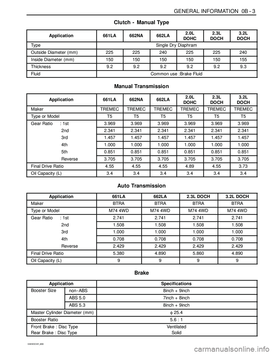
Clutch - Manual Type
Application661LA662NA662LA2.0L
DOHC2.3L
DOCH3.2L
DOCH
Ty p eSingle Dry Diaphram
Outside Diameter (mm)225225240225225240
Inside Diameter (mm)150150150150150155
Thickness9.29.29.29.29.29.3
FluidCommon use :Brake Fluid
Manual Transmission
Application661LA662NA662LA2.0L
DOHC2.3L
DOCH3.2L
DOCH
MakerTREMECTREMECTREMECTREMECTREMECTREMEC
Type or ModelT5T5T5T5T5T5
Gear Ratio : 1st3.9693.9693.9693.9693.9693.969
2nd2.3412.3412.3412.3412.3412.341
3rd1.4571.4571.4571.4571.4571.457
4th1.0001.0001.0001.0001.0001.000
5th0.8510.8510.8510.8510.8510.851
Reverse3.7053.7053.7053.7053.7053.705
Final Drive Ratio4.554.554.554.894.553.73
Oil Capacity (L)3.43.43.43.43.43.4
Auto Transmission
Application661LA662LA2.3L DOCH3.2L DOCH
MakerBTRABTRABTRABTRA
Type or ModelM74 4WDM74 4WDM74 4WDM74 4WD
Gear Ratio : 1st2.7412.7412.7412.741
2nd1.5081.5081.5081.508
3rd1.0001.0001.0001.000
4th0.7080.7080.7080.708
Reverse2.4292.4292.4292.429
Final Drive Ratio5.3804.8905.8604.890
Oil Capacity (L)9999
Brake
ApplicationSpecifications
Booster Sizenon-- ABS8inch + 9inch
ABS 5.07inch + 8inch
ABS 5.38inch + 9inch
Master Cylinder Diameter(mm)φ25.4
Booster Ratio5.6 : 1
Front Brake : Disc Type
Rear Brake : Disc TypeVentilated
Solid
Page 10 of 2053
0B -- 10 GENERAL INFORMATION
D AEW OO M Y_2000
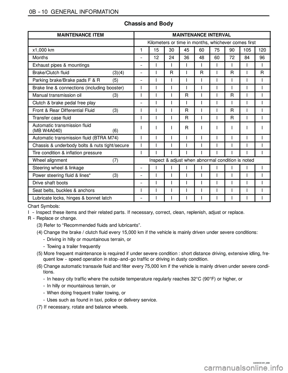
Chassis and Body
MAINTENANCE ITEMMAINTENANCE INTERVAL
Kilometers or time in months, whichever comes first
x1,000 km1153045607590105120
Months--1224364860728496
Exhaust pipes & mountings--IIIIIIII
Brake/Clutch fluid (3)(4)--IRIRIRIR
Parking brake/Brake pads F & R (5)--IIIIIIII
Brake line & connections (including booster)IIIIIIIII
Manual transmission oil (3)IIIRIIRII
Clutch & brake pedal free play--IIIIIIII
Front & Rear Differential Fluid (3)IIIRIIRII
Transfer case fluidIIIRIIRII
Automatic transmission fluid
(MB W4A040) (6)IIIRIIIII
Automatic transmission fluid (BTRA M74)IIIIIIIII
Chassis & underbody bolts & nuts tight/secureIIIIIIIII
Tire condition & inflation pressureIIIIIIIII
Wheel alignment (7)Inspect & adjust when abnormal condition is noted
Steering wheel & linkage--IIIIIIII
Power steering fluid & lines* (3)--IIIIIIII
Drive shaft boots--IIIIIIII
Seat belts, buckles & anchorsIIIIIIIII
Lubricate locks, hinges & bonnet latch--IIIIIIII
Chart Symbols:
I -- Inspect these items and their related parts. If necessary, correct, clean, replenish, adjust or replace.
R -- Replace or change.
(3) Refer to “Recommended fluids and lubricants”.
(4) Change the brake / clutch fluid every 15,000 km if the vehicle is mainly driven under severe conditions:
-- Driving in hilly or mountainous terrain, or
-- Towing a trailer frequently
(5) More frequent maintenance is required if under severe condition : short distance driving, extensive idling, fre-
quent low -- speed operation in stop-- and-- go traffic or driving in dusty condition.
(6) Change automatic transaxle fluid and filter every 75,000 km if the vehicle is mainly driven under severe condi-
tions.
-- In heavy city traffic where the outside temperature regularly reaches 32°C(90°F) or higher, or
-- In hilly or mountainous terrain, or
-- When doing frequent trailer towing, or
-- Uses such as found in taxi, police or delivery service.
(7) If necessary, rotate and balance wheels.
Page 12 of 2053
0B -- 12 GENERAL INFORMATION
D AEW OO M Y_2000
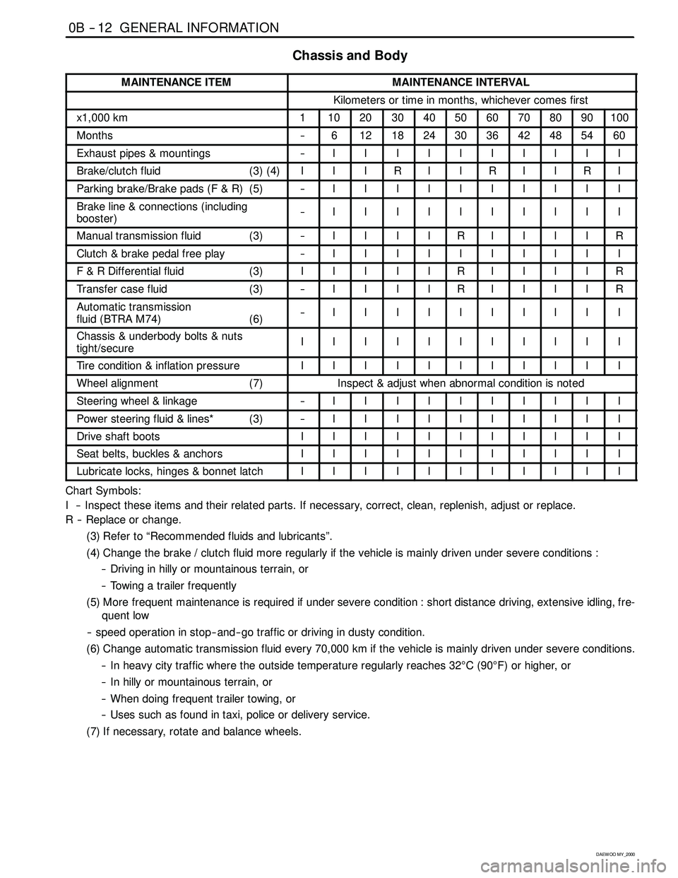
Chassis and Body
MAINTENANCE ITEMMAINTENANCE INTERVAL
Kilometers or time in months, whichever comes first
x1,000 km1102030405060708090100
Months--6121824303642485460
Exhaust pipes & mountings--IIIIIIIIII
Brake/clutch fluid (3) (4)IIIRIIRIIRI
Parking brake/Brake pads (F & R) (5)--IIIIIIIIII
Brake line & connections (including
booster)--IIIIIIIIII
Manual transmission fluid (3)--IIIIRIIIIR
Clutch & brake pedal free play--IIIIIIIIII
F & R Differential fluid (3)IIIIIRIIIIR
Transfer case fluid (3)--IIIIRIIIIR
Automatic transmission
fluid (BTRA M74) (6)--IIIIIIIIII
Chassis & underbody bolts & nuts
tight/secureIIIIIIIIIII
Tire condition & inflation pressureIIIIIIIIIII
Wheel alignment (7)Inspect & adjust when abnormal condition is noted
Steering wheel & linkage--IIIIIIIIII
Power steering fluid & lines* (3)--IIIIIIIIII
Drive shaft bootsIIIIIIIIIII
Seat belts, buckles & anchorsIIIIIIIIIII
Lubricate locks, hinges & bonnet latchIIIIIIIIIII
Chart Symbols:
I -- Inspect these items and their related parts. If necessary, correct, clean, replenish, adjust or replace.
R -- Replace or change.
(3) Refer to “Recommended fluids and lubricants”.
(4) Change the brake / clutch fluid more regularly if the vehicle is mainly driven under severe conditions :
-- Driving in hilly or mountainous terrain, or
-- Towing a trailer frequently
(5) More frequent maintenance is required if under severe condition : short distance driving, extensive idling, fre-
quent low
-- speed operation in stop-- and-- go traffic or driving in dusty condition.
(6) Change automatic transmission fluid every 70,000 km if the vehicle is mainly driven under severe conditions.
-- In heavy city traffic where the outside temperature regularly reaches 32°C(90°F) or higher, or
-- In hilly or mountainous terrain, or
-- When doing frequent trailer towing, or
-- Uses such as found in taxi, police or delivery service.
(7) If necessary, rotate and balance wheels.
Page 26 of 2053
1A1 -- 6 GENERAL ENGINE INFORMATION
D AEW OO M Y_2000
DIAGNOSIS
OIL LEAK DIAGNOSIS
Most fluid oil leaks are easily located and repaired by
visually finding the leak and replacing or repairing the
necessary parts. On some occasions a fluid leak may be
difficult to locate or repair. The following procedures may
help you in locating and repairing most leaks.
Finding the Leak
1. Identify the fluid. Determine whether it is engine oil,
automatic transmission fluid, power steering fluid,
etc.
2. Identify where the fluid is leaking from.
2.1 After running the vehicle at normal operating
temperature, park the vehicle over a large sheet
of paper.
2.2 Wait a few minutes.
2.3 You should be able to find the approximate loca-
tion of the leak by the drippings on the paper.
3. Visually check around the suspected component.
Check around all the gasket mating surfaces for
leaks. A mirror is useful for finding leaks in areas that
are hard to reach.
4. If the leak still cannot be found, it may be necessary
to clean the suspected area with a degreaser, steam
or spray solvent.
4.1 Clean the area well.
4.2 Dry the area.
4.3 Operate the vehicle for several miles at normal
operating temperature and varying speeds.
4.4 After operating the vehicle, visually check the
suspected component.
4.5 If you still cannot locate the leak, try using the
powder or black light and dye method.
Powder Method
1. Clean the suspected area.
2. Apply an aerosol-- type powder (such as foot powder)
to the suspected area.
3. Operate the vehicle under normal operating condi-
toins.
4. Visually inspect the suspected component. You
should be able to trace the leak path over the white
powder surface to the source.
Black Light and Dye Method
A dye and light kit is available for finding leaks, Refer to
the manufacturer ’s directions when using the kit.
1. Pour the specified amount of dye into the engine oil fill
tube.
2. Operate the vehicle normal operating conditions as
directed in the kit.
3. Direct the light toward the suspected area. The dyed
fluid willappear as a yellow path leading to the
source.
Repairing the Leak
Once the origin of the leak has been pinpointed and
traced back to its source, the cause of the leak must be
determined n order for it to be repaired properly. If a gas-
ket is replaced, but the sealing flange is bent, the new
gasket will not repair the leak. Thebent flange must be
repaired also. Before attempting to repair a leak, check
for the following conditions and correct them as they
may cause a leak.
Gaskets
DThe fluid level/pressure is too high.
DThe crankcase ventilation system is malfunctioning.
DThe fasteners are tightened improperly or the threads
are dirty or damaged.
DThe flanges or the sealing surface is warped.
DThere are scratches, burrs or other damage to the
sealing surface.
DThe gasket is damaged or worn.
DThere is cracking or porosity of the component.
DAn improper seal was used (where applicable).
Seals
DThe fluid level/pressure is too high.
DThe crankcase ventilation system is malfunctioning.
DThe seal bore is damaged (scratched, burred or
nicked).
DThe seal is damaged or worn.
DImproper installation is evident.
DThere are cracks in the components.
DThe shaft surface is scratched, nicked or damaged.
DA loose or worn bearing is causing excess seal wear.
Page 34 of 2053
1B1 -- 2 M162 ENGINE MECHANICAL
D AEW OO M Y_2000
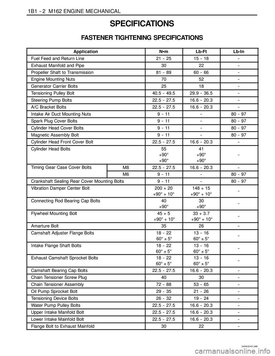
SPECIFICATIONS
FASTENER TIGHTENING SPECIFICATIONS
ApplicationNSmLb-FtLb-In
Fuel Feed and Return Line21 -- 2515 -- 18--
Exhaust Manifold and Pipe3022--
Propeller Shaft to Transmission81 -- 8960 -- 66--
Engine Mounting Nuts7052--
Generator Carrier Bolts2518--
Tensioning Pulley Bolt40.5 -- 49.529.9 -- 36.5--
Steering Pump Bolts22.5 -- 27.516.6 -- 20.3--
A/C Bracket Bolts22.5 -- 27.516.6 -- 20.3--
Intake Air Duct Mounting Nuts9--11--80 -- 97
Spark Plug Cover Bolts9--11--80 -- 97
Cylinder Head Cover Bolts9--11--80 -- 97
Magnetic Assembly Bolt9--11--80 -- 97
Cylinder Head Front Cover Bolt22.5 -- 27.516.6 -- 20.3--
Cylinder Head Bolts55
+90°
+90°41
+90°
+90°
--
Timing Gear Case Cover BoltsM822.5 -- 27.516.6 -- 20.3--g
M69--11--80 -- 97
Crankshaft Sealing Rear Cover Mounting Bolts9--11--80 -- 97
Vibration Damper Center Bolt200 + 20
+90°+10°148 + 15
+90°+10°--
Connecting Rod Bearing Cap Bolts40
+90°30
+90°--
Flywheel Mounting Bolt45 + 5
+90°+10°33 + 3.7
+90°+10°--
Amarture Bolt3526--
Camshaft Adjuster Flange Bolts18 -- 22
60°±5°13 -- 16
60°±5°--
Intake Flange Shaft Bolts18 -- 22
60°±5°13 -- 16
60°±5°--
Exhaust Camshaft Sprocket Bolts18 -- 22
60°±5°13 -- 16
60°±5°--
Camshaft Bearing Cap Bolts22.5 -- 27.516.6 -- 20.3--
Chain Tensioner Screw Plug4030--
Chain Tensioner Assembly72 -- 8853 -- 65--
Oil Pump Sprocket Bolt29 -- 3521 -- 26--
Tensioning Device Bolts26 -- 3219 -- 24--
Water Pump Pulley Bolts22.5 -- 27.516.6 -- 20.3--
Upper Intake Manifold Bolt22.5 -- 27.516.6 -- 20.3--
Lower Intake Mainfold Bolt22.5 -- 27.516.6 -- 20.3--
Flange Bolt to Exhaust Mainfold3022--
Page 44 of 2053
1B1 -- 12 M162 ENGINE MECHANICAL
D AEW OO M Y_2000
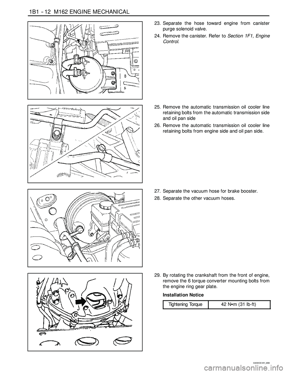
23. Separate the hose toward engine from canister
purge solenoid valve.
24. Remove the canister. Refer toSection 1F1, Engine
Control.
25. Remove the automatic transmission oil cooler line
retaining bolts from the automatic transmission side
and oil pan side
26. Remove the automatic transmission oil cooler line
retaining bolts from engine side and oil pan side.
27. Separate the vacuum hose for brake booster.
28. Separate the other vacuum hoses.
29. By rotating the crankshaft from the front of engine,
remove the 6 torque converter mounting bolts from
the engine ring gear plate.
Installation Notice
Tightening Torque
42 NSm (31 lb-ft)
Page 45 of 2053

M162 ENGINE MECHANICAL 1B1 -- 13
D AEW OO M Y_2000
30. Remove the exhaust manifold and exhaust pipe.
Installation Notice
Tightening Torque
30 NSm (22 lb-ft)
31. Remove the transmission.Refer to Section 5A, Au-
tomatic Transmission.
32. Install a chain to the bracket of engine, by using a
hoist or crane.
33. Remove the engine mount nuts.
Installation Notice
Tightening Torque
70 NSm (52 lb-ft)
34. Carefully separate the engine assembly from the ve-
hicle.
35. Installation should follow the removal procedure in
the reverse order.
Page 65 of 2053
M162 ENGINE MECHANICAL 1B1 -- 33
D AEW OO M Y_2000
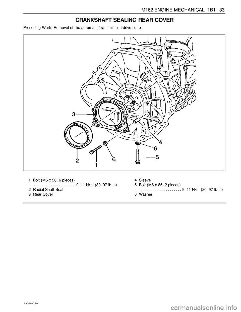
CRANKSHAFT SEALING REAR COVER
Preceding Work: Removal of the automatic transmission drive plate
1 Bolt (M6 x 20, 6 pieces)
9--11 NSm (80-- 97 lb-in) .....................
2 Radial Shaft Seal
3 Rear Cover4 Sleeve
5 Bolt (M6 x 85, 2 pieces)
9--11 NSm (80-- 97 lb-in) .....................
6Washer
Page 79 of 2053
M162 ENGINE MECHANICAL 1B1 -- 47
D AEW OO M Y_2000
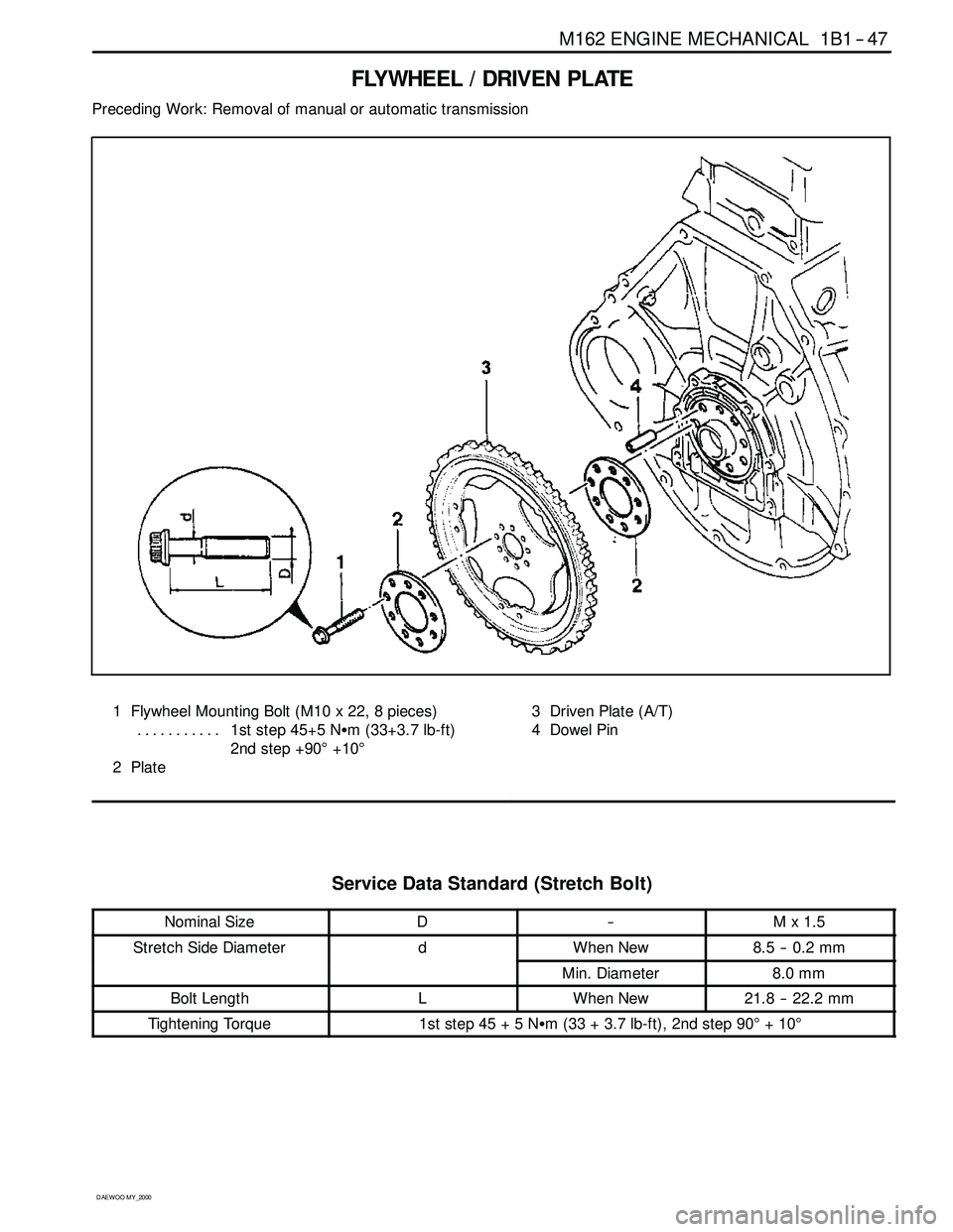
FLYWHEEL / DRIVEN PLATE
Preceding Work: Removal of manual or automatic transmission
1 Flywheel Mounting Bolt (M10 x 22, 8 pieces)
1st step 45+5 NSm (33+3.7 lb-ft) ...........
2nd step +90°+10°
2Plate3 Driven Plate (A/T)
4 Dowel Pin
Service Data Standard (Stretch Bolt)
Nominal SizeD--Mx1.5
Stretch Side DiameterdWhen New8.5 -- 0.2 mm
Min. Diameter8.0 mm
Bolt LengthLWhen New21.8 -- 22.2 mm
Tightening Torque1ststep45+5NSm (33 + 3.7 lb-ft), 2nd step 90°+10°
Page 80 of 2053
1B1 -- 48 M162 ENGINE MECHANICAL
D AEW OO M Y_2000
Removal & Installation Procedure
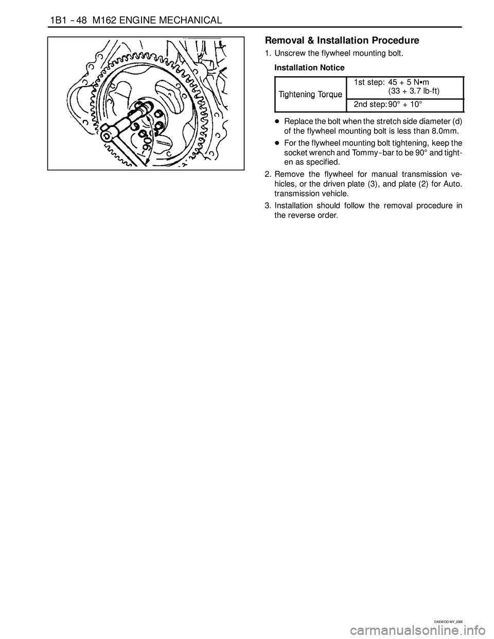
1. Unscrew the flywheel mounting bolt.
Installation Notice
Ti
ghteningTo rque
1st step: 45 + 5 NSm
(33+3.7lb-ft)
TighteningTorque
2nd step: 90°+10°
DReplace the bolt when the stretch side diameter (d)
of the flywheel mounting bolt is less than 8.0mm.
DFor the flywheel mounting bolt tightening, keep the
socket wrench and Tommy -- bar to be 90°and tight-
en as specified.
2. Remove the flywheel for manual transmission ve-
hicles, or the driven plate (3), and plate (2) for Auto.
transmission vehicle.
3. Installation should follow the removal procedure in
the reverse order.