oil type SSANGYONG KORANDO 2012 Owner's Manual
[x] Cancel search | Manufacturer: SSANGYONG, Model Year: 2012, Model line: KORANDO, Model: SSANGYONG KORANDO 2012Pages: 1082, PDF Size: 96.1 MB
Page 830 of 1082

01-20
Steering gear box assembly
The steering gear box assembly consists of power cylinder and control valve. The power cylinder has a
cylinder, piston and piston rod. The control valve directs the oil to one end face of the piston to enhance
the steering force. There is a safety check valve which lets the driver steer manually when there is a
malfunction in the hydraulic circuit.
8. STEERING SYSTEM LAYOUT
1) HPS (Hydraulic Power Steering)
The hydraulic pump is a vane
type pump and consists of the
flow control valve and pressure
relief valve.The oil reservoir sends the oil to
the power steering pump and
receives the oil from the power
steering gear.There is a shock absorber which
is folded in the axial direction
when the vehicle is crashed and
a ignition switch assembly on
the column shaft.
The lower shaft minimizes the
torque change using a CV joint
which has constant angular
speed.
Tie rod endSteering cylinderGear box
Tie rod end
Hydraulic pipeColumn shaft
Lower shaft
Steering wheel
assembly
Hydraulic pipe & hose
Page 833 of 1082
01-230000-00
3) General Instructions
Before lifting up the vehicle with a lift, correctly support the lifting points.
When using a jack, park the vehicle on a level ground and place the wheel chocks under the tires.
Position the jack under the frame and lift up the vehicle and then support with chassis stand before
service work.
Make sure to disconnect the negative (-) cable from the battery to prevent any damage to electric
systems.
If you have to work on vehicle, cover the seats and floor with protection covers to avoid any
damage and contamination.
Brake fluid and anti-freeze can damage the painted surface of body. So carefully handle them
during service work.
To improve the efficiency of service work, use only recommended and specified tools.
Use only Ssangyong genuine spare parts.
Never reuse the cotter pin, gasket, O-ring, oil seal, lock washer and self-locking nut. Replace them
with new ones. If reused, normal functions cannot be maintained.
Store the disassembled parts as a set based on disassembly order and unit.
Pay particular attention not to miss or mix the fasteners.
If necessary, especially for inspection, clean the removed parts completely.
Apply the oil or grease on the running and sliding surfeces before installation. Use the specified
sealant and gasket to prevent leakage if necessary.
Tighten the fasteners to the specified tightening torque.
As a final stage of service work, check if the serviced system is working properly and the problem
has been eliminated clearly. (1)
(2)
(3)
(4)
(5)
(6)
(7)
(8)
(9)
(10)
(11)
(12)
(13)
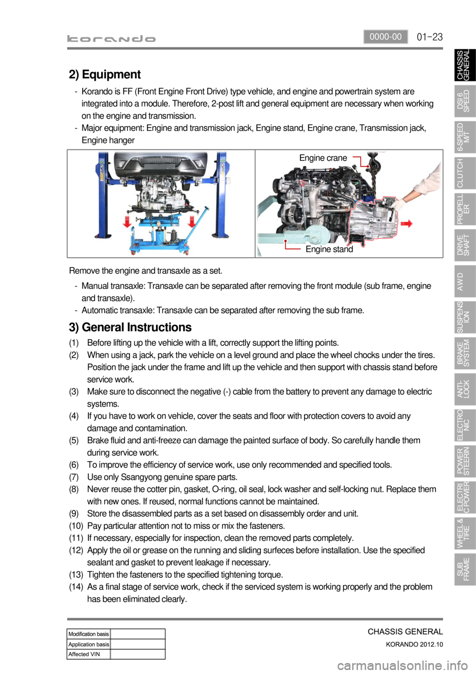
(14) Remove the engine and transaxle as a set.
Manual transaxle: Transaxle can be separated after removing the front module (sub frame, engine
and transaxle).
Automatic transaxle: Transaxle can be separated after removing the sub frame. -
-
2) Equipment
Korando is FF (Front Engine Front Drive) type vehicle, and engine and powertrain system are
integrated into a module. Therefore, 2-post lift and general equipment are necessary when working
on the engine and transmission.
Major equipment: Engine and transmission jack, Engine stand, Engine crane, Transmission jack,
Engine hanger -
-
Engine stand
Engine crane
Page 837 of 1082
02-33680-01
1. GENERAL INFORMATION
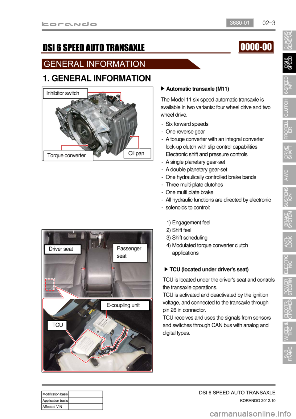
Automatic transaxle (M11) ▶
The Model 11 six speed automatic transaxle is
available in two variants: four wheel drive and two
wheel drive.
Six forward speeds
One reverse gear
A toruqe converter with an integral converter
lock-up clutch with slip control capabilities
Electronic shift and pressure controls
A single planetary gear-set
A double planetary gear-set
One hydraulically controlled brake bands
Three multi-plate clutches
One multi plate brake
All hydraulic functions are directed by electronic
solenoids to control: -
-
-
-
-
-
-
-
-
-
Engagement feel
Shift feel
Shift scheduling
Modulated torque converter clutch
applications 1)
2)
3)
4) Inhibitor switch
Oil pan
Torque converter
TCU (located under driver's seat) ▶
TCU is located under the driver's seat and controls
the transaxle operations.
TCU is activated and deactivated by the ignition
voltage, and connected to the transaxle through
pin 26 in connector.
TCU receives and uses the signals from sensors
and switches through CAN bus with analog and
digital types. Driver seat
E-coupling unit
TCU
Passenger
seat
Page 839 of 1082
02-53680-01
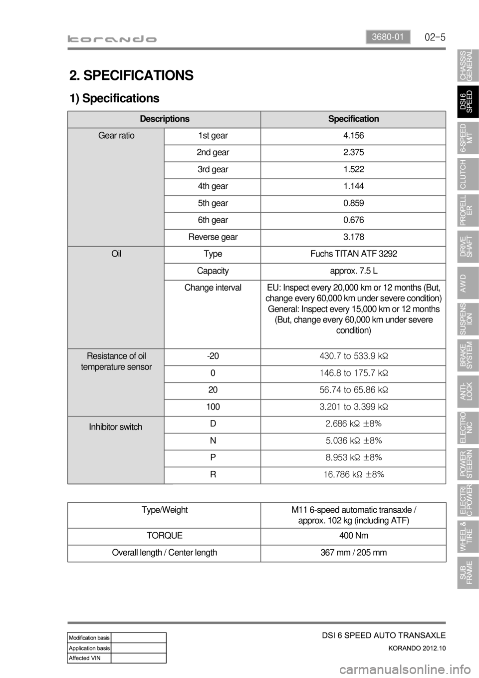
2. SPECIFICATIONS
1) Specifications
Type/Weight M11 6-speed automatic transaxle /
approx. 102 kg (including ATF)
TORQUE 400 Nm
Overall length / Center length 367 mm / 205 mm
Descriptions Specification
Gear ratio 1st gear 4.156
2nd gear 2.375
3rd gear 1.522
4th gear 1.144
5th gear 0.859
6th gear 0.676
Reverse gear 3.178
Oil Type Fuchs TITAN ATF 3292
Capacity approx. 7.5 L
Change interval EU: Inspect every 20,000 km or 12 months (But,
change every 60,000 km under severe condition)
General: Inspect every 15,000 km or 12 months
(But, change every 60,000 km under severe
condition)
Resistance of oil
temperature sensor-20430.7 to 533.9 kΩ
0146.8 to 175.7 kΩ
2056.74 to 65.86 kΩ
1003.201 to 3.399 kΩ
D2.686 kΩ ±8%
N5.036 kΩ ±8%
P8.953 kΩ ±8%
R16.786 kΩ ±8%
Inhibitor switch
Page 842 of 1082
02-8
1. OVERVIEW
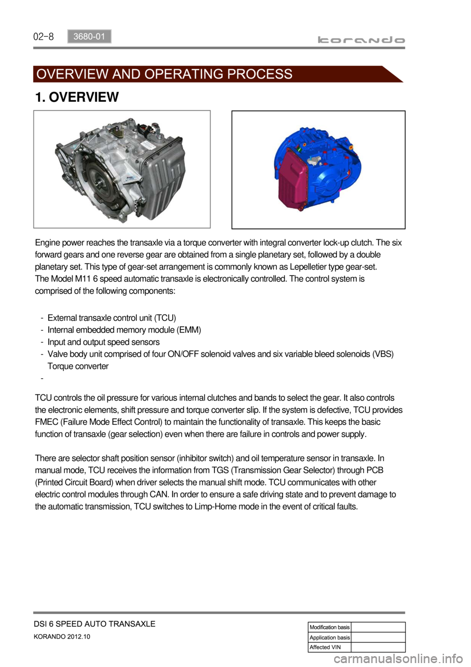
Engine power reaches the transaxle via a torque converter with integral converter lock-up clutch. The six
forward gears and one reverse gear are obtained from a single planetary set, followed by a double
planetary set. This type of gear-set arrangement is commonly known as Lepelletier type gear-set.
The Model M11 6 speed automatic transaxle is electronically controlled. The control system is
comprised of the following components:
External transaxle control unit (TCU)
Internal embedded memory module (EMM)
Input and output speed sensors
Valve body unit comprised of four ON/OFF solenoid valves and six variable bleed solenoids (VBS)
Torque converter -
-
-
-
-
TCU controls the oil pressure for various internal clutches and bands to select the gear. It also controls
the electronic elements, shift pressure and torque converter slip. If the system is defective, TCU provides
FMEC (Failure Mode Effect Control) to maintain the functionality of transaxle. This keeps the basic
function of transaxle (gear selection) even when there are failure in controls and power supply.
There are selector shaft position sensor (inhibitor switch) and oil temperature sensor in transaxle. In
manual mode, TCU receives the information from TGS (Transmission Gear Selector) through PCB
(Printed Circuit Board) when driver selects the manual shift mode. TCU communicates with other
electric control modules through CAN. In order to ensure a safe driving state and to prevent damage to
the automatic transmission, TCU switches to Limp-Home mode in the event of critical faults.
Page 864 of 1082
03-4
2. GENERAL INFORMATION
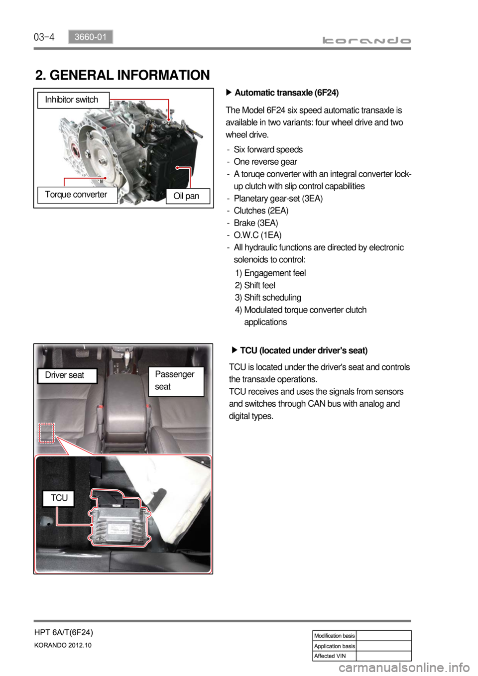
Automatic transaxle (6F24) ▶
The Model 6F24 six speed automatic transaxle is
available in two variants: four wheel drive and two
wheel drive.
Six forward speeds
One reverse gear
A toruqe converter with an integral converter lock-
up clutch with slip control capabilities
Planetary gear-set (3EA)
Clutches (2EA)
Brake (3EA)
O.W.C (1EA)
All hydraulic functions are directed by electronic
solenoids to control: -
-
-
-
-
-
-
-
Engagement feel
Shift feel
Shift scheduling
Modulated torque converter clutch
applications 1)
2)
3)
4) Inhibitor switch
Oil pan
Torque converter
TCU (located under driver's seat) ▶
TCU is located under the driver's seat and controls
the transaxle operations.
TCU receives and uses the signals from sensors
and switches through CAN bus with analog and
digital types. Driver seat
TCU
Passenger
seat
Page 866 of 1082
03-6
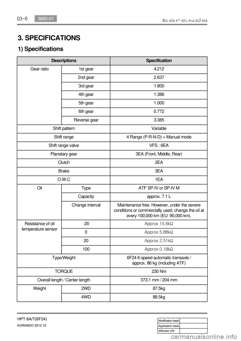
3. SPECIFICATIONS
1) Specifications
Type/Weight 6F24 6-speed automatic transaxle /
approx. 86 kg (including ATF)
TORQUE 230 Nm
Overall length / Center length 373.1 mm / 204 mm
Descriptions Specification
Gear ratio 1st gear 4.212
2nd gear 2.637
3rd gear 1.800
4th gear 1.386
5th gear 1.000
6th gear 0.772
Reverse gear 3.385
Shift pattern Variable
Shift range 4 Range (P-R-N-D) + Manual mode
Shift range valve VFS : 6EA
Planetary gear 3EA (Front, Middle, Rear)
Clutch 2EA
Brake 3EA
O.W.C 1EA
Oil Type ATF SP-IV or SP-IV M
Capacity approx. 7.1 L
Change interval Maintenance free. However, under the severe
conditions or commercially used, change the oil at
every 100,000 km (EU: 90,000 km).
Resistance of oil
temperature sensor-20Approx 15.6kΩ
0Approx 5.88kΩ
20Approx 2.51kΩ
100Approx 0.18kΩ
Weight 2WD 87.5kg
4WD 88.5kg
Page 893 of 1082

03-8
1) Characteristics of WM6F1 M/T
Both Forward and Reverse gears use the helical gear and are made of high-strength material.
Drives the clutch with a concentric slave cylinder mounting bolt.
Shifting the transmission gears is performed through the remote control cable.
A pull type clutch is used for Reverse gear shifting.
Features triple/double/single synchronization. -
-
-
-
-
Clutch housing
Transmission case
Input shaft
Concentric slave cylinder
Shift lever
Selector lever
Wiring bracket
Neutral switch
Backup lamp switch
Reverse idle shaft mounting bolt 1.
2.
3.
4.
5.
6.
7.
8.
9.
10.Control guide bolt
Oil filler plug (for servicing)
Oil drain plug
Oil filler plug (for manufacturing)
Air breather
Detent pin (for securing shift fork)
Oil seal (RH)
Oil seal (LH)
Control housing 11.
12.
13.
14.
15.
16.
17.
18.
19.
Page 899 of 1082
04-30000-00
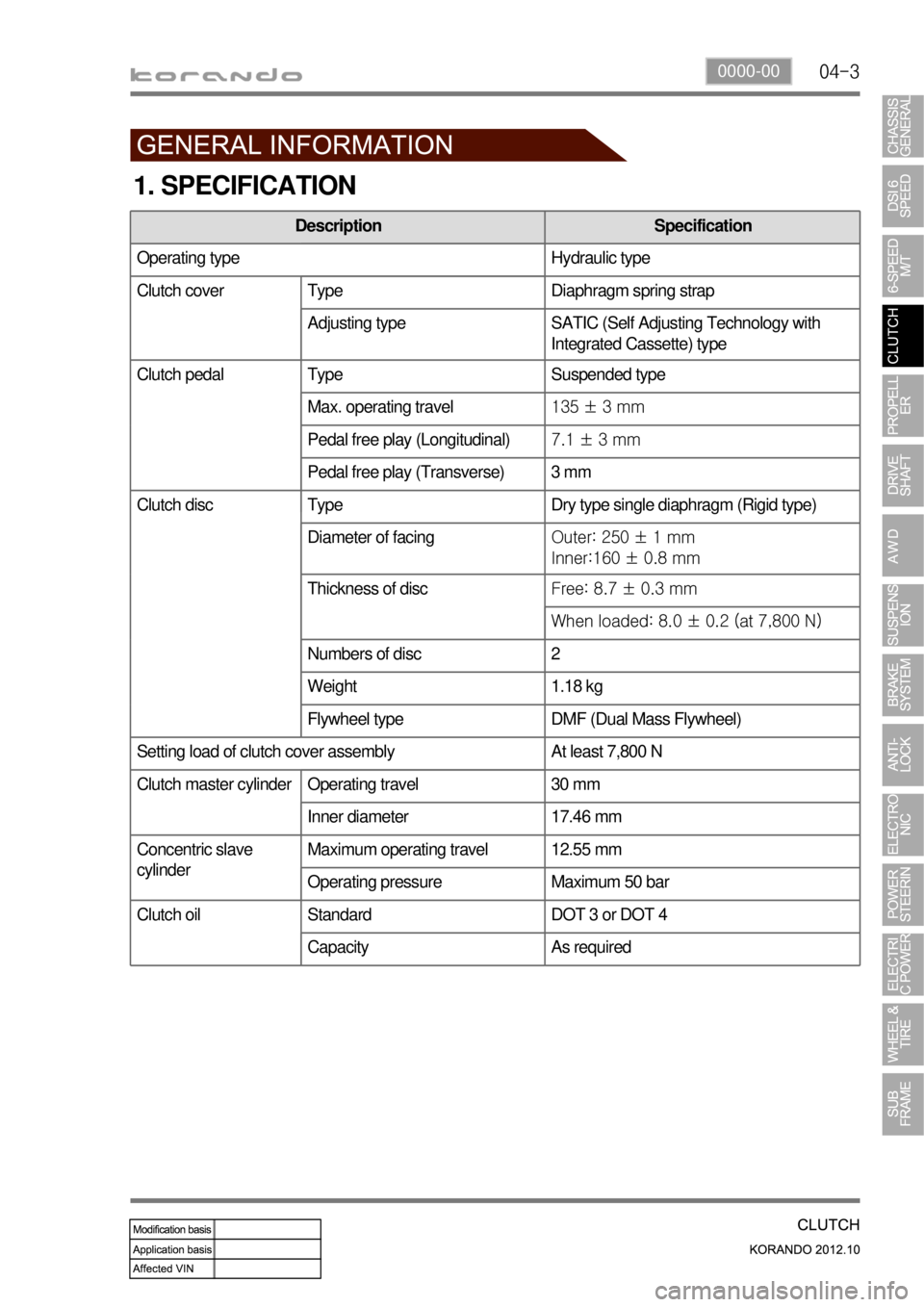
1. SPECIFICATION
Description Specification
Operating type Hydraulic type
Clutch cover Type Diaphragm spring strap
Adjusting type SATIC (Self Adjusting Technology with
Integrated Cassette) type
Clutch pedal Type Suspended type
Max. operating travel135 ± 3 mm
Pedal free play (Longitudinal)7.1 ± 3 mm
Pedal free play (Transverse) 3 mm
Clutch disc Type Dry type single diaphragm (Rigid type)
Diameter of facingOuter: 250 ± 1 mm
Inner:160 ± 0.8 mm
Thickness of discFree: 8.7 ± 0.3 mm
When loaded: 8.0 ± 0.2 (at 7,800 N)
Numbers of disc 2
Weight 1.18 kg
Flywheel type DMF (Dual Mass Flywheel)
Setting load of clutch cover assembly At least 7,800 N
Clutch master cylinder Operating travel 30 mm
Inner diameter 17.46 mm
Concentric slave
cylinderMaximum operating travel 12.55 mm
Operating pressure Maximum 50 bar
Standard DOT 3 or DOT 4
Capacity As required
Clutch oil
Page 909 of 1082

06-34110-01
1. SPECIFICATION
Component Item Specifications
2WD,
4WDFront drive
shaftJoint type Inside: Tripod joint
Outside: Ball joint
Max. allowed angleInside: 23°
Outside: 46°
To compensate the bending
angleInstallation of equivalent
length shaft
Rear drive
shaftJoint type Inside: Cross groove joint
Outside: Ball joint
Max. allowed angleInside: 23°
Outside: 23°
Rear differential
carrierType Independent Rear Drive Axle
(IRDA)
Reduction gear type Hypoid gear
Gear reduction ratio 2.93
Diameter of gearØ152 mm
Oil type Hypoid gear oil
(SAE 75W/90)
Final drive gear backlash 0.10 to 0.15 mm
Differential gear backlash 0 to 0.076 mm
Propeller shaft Joint type PTU side: CV joint
Rear axle side: Rubber coupling
Sliding distance±25 mm or more
Unbalance 80 g.mm or less at 3,000 rpm
Total runout 0.3 mm or less
4WD
only