ESP SSANGYONG KORANDO 2012 Service Manual
[x] Cancel search | Manufacturer: SSANGYONG, Model Year: 2012, Model line: KORANDO, Model: SSANGYONG KORANDO 2012Pages: 1082, PDF Size: 96.1 MB
Page 103 of 1082
01-70000-00
3) General Instructions
Before lifting up the vehicle with a lift, correctly support the lifting points.
When using a jack, park the vehicle on a level ground and place the wheel chocks under the tires.
Position the jack under the frame and lift up the vehicle and then support with chassis stand before
service work.
Make sure to disconnect the negative (-) cable from the battery to prevent any damage to electric
systems.
If you have to work on vehicle, cover the seats and floor with protection covers to avoid any
damage and contamination.
Brake fluid and anti-freeze can damage the painted surface of body. So carefully handle them
during service work.
To improve the efficiency of service work, use only recommended and specified tools.
Use only Ssangyong genuine spare parts.
Never reuse the cotter pin, gasket, O-ring, oil seal, lock washer and self-locking nut. Replace them
with new ones. If reused, normal functions cannot be maintained.
Store the disassembled parts as a set based on disassembly order and unit.
Pay particular attention not to miss or mix the fasteners.
If necessary, especially for inspection, clean the removed parts completely.
Apply the oil or grease on the running and sliding surfeces before installation. Use the specified
sealant and gasket to prevent leakage if necessary.
Tighten the fasteners with the specified tightening torque.
As a final stage of service work, check if the serviced system is working properly and the problem
has been eliminated clearly. (1)
(2)
(3)
(4)
(5)
(6)
(7)
(8)
(9)
(10)
(11)
(12)
(13)
(14)
(15) Remove the engine and transaxle as a set.
Korando is FF (Front Engine Front Drive) type vehicle, and engine and powertrain system are
integrated into a module. Therefore, 2-post lift and general equipment are necessary when working
on the engine and transmission.
Major equipment: Engine and transmission jack, Engine stand, Engine crane, Transmission jack,
Engine hanger -
-
Page 134 of 1082
02-270000-00
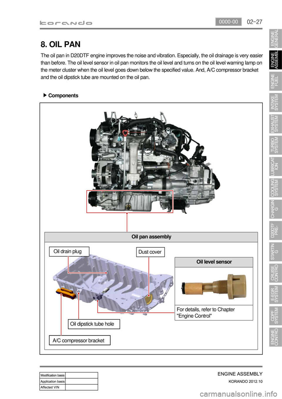
Oil pan assembly
8. OIL PAN
The oil pan in D20DTF engine improves the noise and vibration. Especially, the oil drainage is very easier
than before. The oil level sensor in oil pan monitors the oil level and turns on the oil level warning lamp on
the meter cluster when the oil level goes down below the specified value. And, A/C compressor bracket
and the oil dipstick tube are mounted on the oil pan.
Components ▶
Oil drain plugDust cover
Oil dipstick tube hole
A/C compressor bracket
Oil level sensor
For details, refer to Chapter
"Engine Control"
Page 139 of 1082
03-4
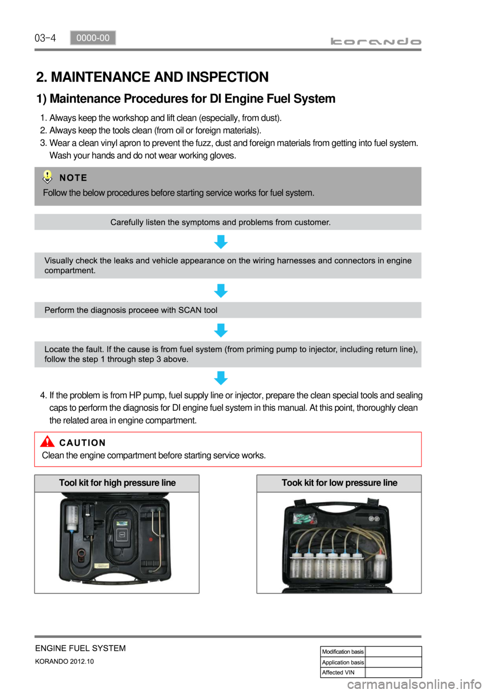
2. MAINTENANCE AND INSPECTION
1) Maintenance Procedures for DI Engine Fuel System
Always keep the workshop and lift clean (especially, from dust).
Always keep the tools clean (from oil or foreign materials).
Wear a clean vinyl apron to prevent the fuzz, dust and foreign materials from getting into fuel system.
Wash your hands and do not wear working gloves. 1.
2.
3.
Follow the below procedures before starting service works for fuel system.
If the problem is from HP pump, fuel supply line or injector, prepare the clean special tools and sealing
caps to perform the diagnosis for DI engine fuel system in this manual. At this point, thoroughly clean
the related area in engine compartment. 4.
Clean the engine compartment before starting service works.
Tool kit for high pressure lineTook kit for low pressure line
Page 183 of 1082
06-6
3) Inspection of Turbine
Thoroughly check the followings.
Interference: In case where is trace of interference or smallest damage on the compressor wheel
means, most of times, that abrasion has occurred on the journal bearing. Must inspect after the
overhaul.
Oil Leakage: The reason for oil leakage at the compressor section is the air cleaner, clogged by
substances such as dust, causes the compressor inlet negative pressure. -
-
Rotating in high speed at no-load for extended period of time can cause oil leakage to the
compressor section as oil pressure within the center housing gets higher than pressure within the
compressor housing.
Overuse of engine break (especially in low gear) in down hill makes significantly low exhaust gas
energy compared to the time where great amount of air is required during idling conditions of the
engine. Therefore, amount of air in the compressor inlet increases but the turbocharge pressure
is not high, which makes negative pressure at the compressor section causing the oilleakage
within the center housing. a.
b.
No problem will occur with the turbocharger if above conditions are found in early stage but oil
leaked over long period of time will solidify at each section causing to breakout secondary
defects.
Damages by foreign materials: In case where the compressor wheel is damaged by foreign materials
requires having an overhaul. At this time, it's necessary to check whether the foreign materials have
contaminated intake/exhaust manifold or inside of engine.
Must absolutely not operate the turbocharger with the compressor outlet and inlet opened
as it could damage the turbocharger or be hazardous during inspection.
Page 195 of 1082
06-18
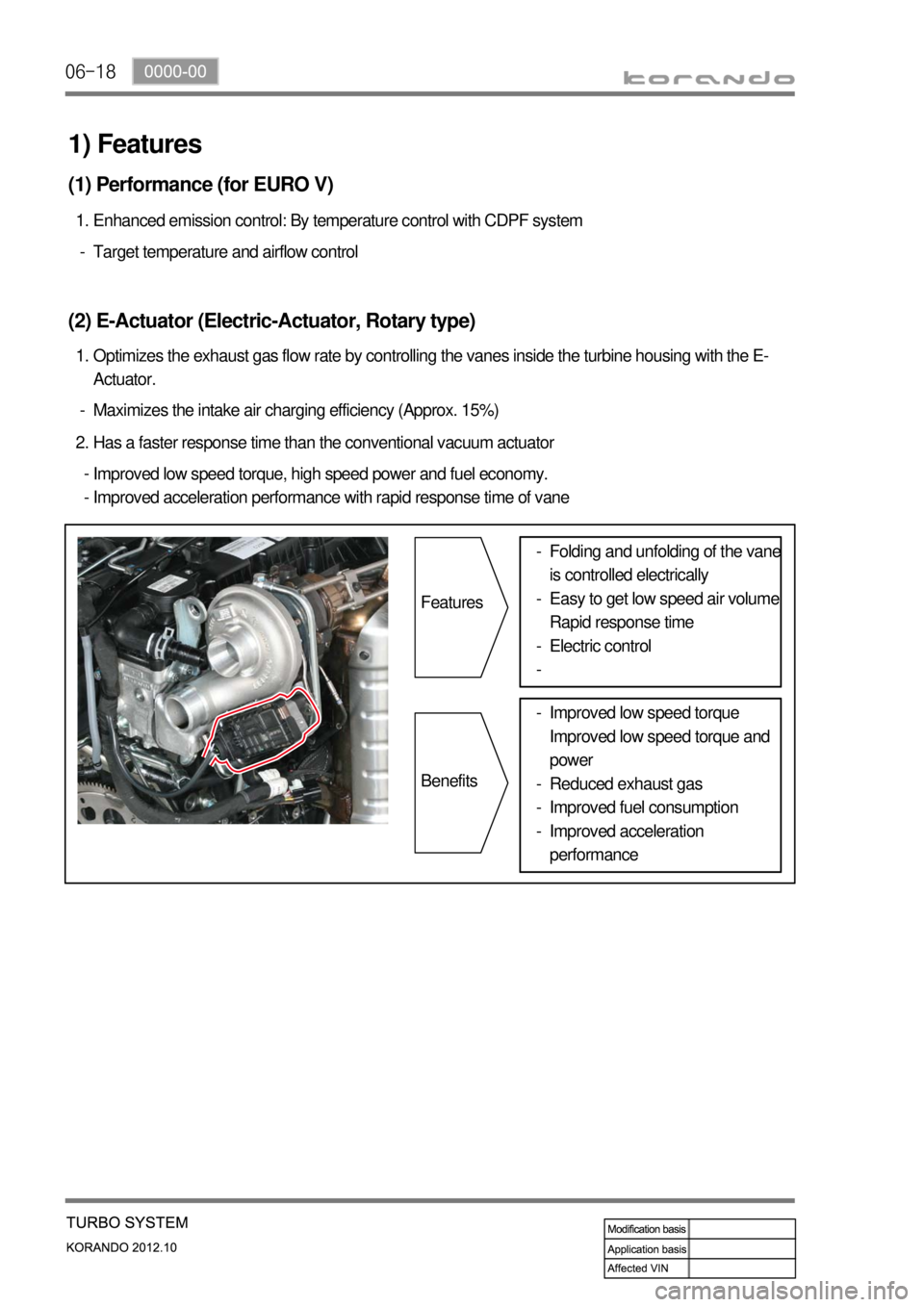
Maximizes the intake air charging efficiency (Approx. 15%) -Optimizes the exhaust gas flow rate by controlling the vanes inside the turbine housing with the E-
Actuator. 1.
(2) E-Actuator (Electric-Actuator, Rotary type)
Target temperature and airflow control -Enhanced emission control: By temperature control with CDPF system 1.
(1) Performance (for EURO V)
Has a faster response time than the conventional vacuum actuator 2.
Improved low speed torque, high speed power and fuel economy.
Improved acceleration performance with rapid response time of vane -
-
1) Features
Features
BenefitsFolding and unfolding of the vane
is controlled electrically
Easy to get low speed air volume
Rapid response time
Electric control -
-
-
-
Improved low speed torque
Improved low speed torque and
power
Reduced exhaust gas
Improved fuel consumption
Improved acceleration
performance -
-
-
-
Page 222 of 1082
09-10
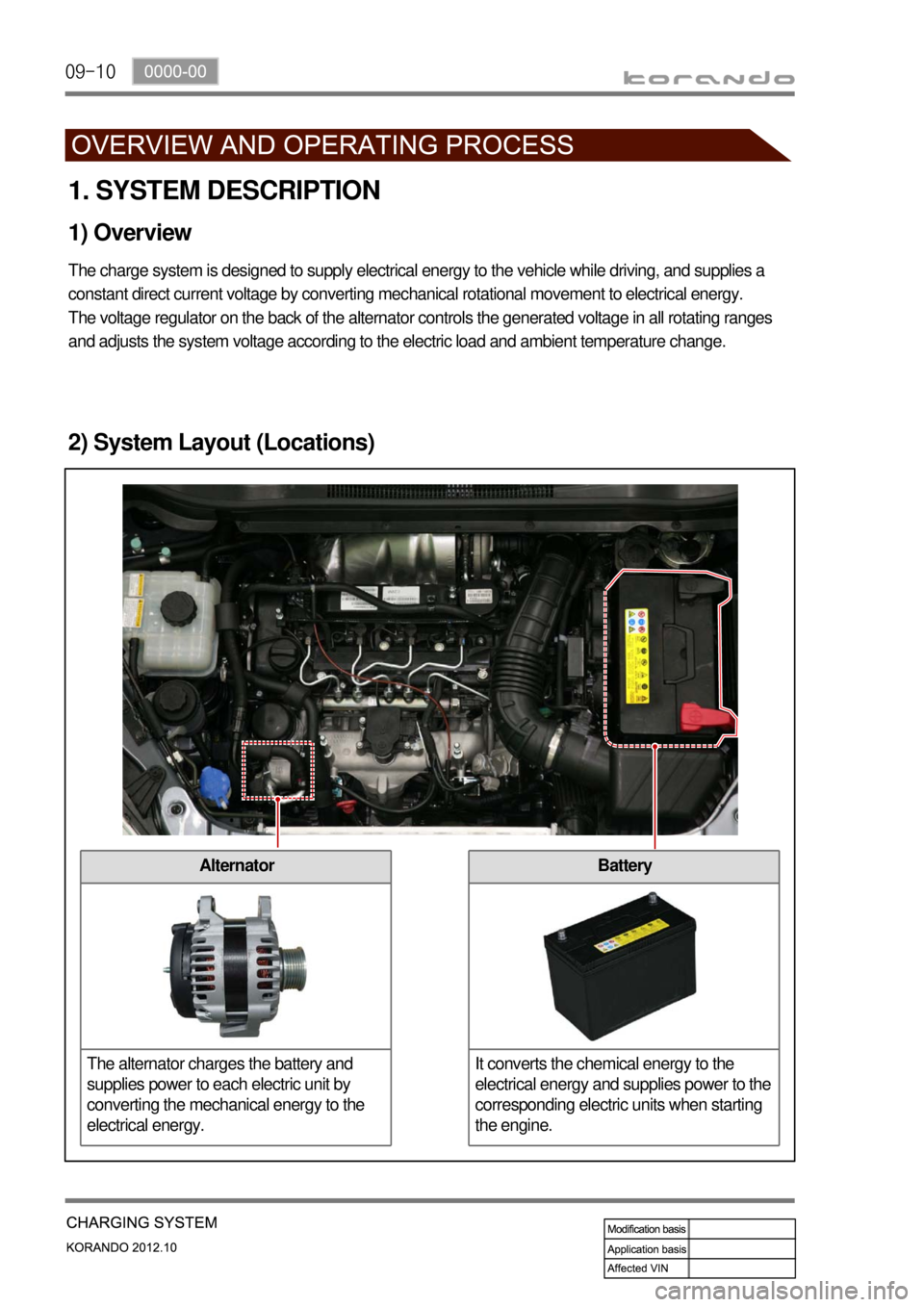
Battery
It converts the chemical energy to the
electrical energy and supplies power to the
corresponding electric units when starting
the engine.Alternator
The alternator charges the battery and
supplies power to each electric unit by
converting the mechanical energy to the
electrical energy.
1. SYSTEM DESCRIPTION
1) Overview
The charge system is designed to supply electrical energy to the vehicle while driving, and supplies a
constant direct current voltage by converting mechanical rotational movement to electrical energy.
The voltage regulator on the back of the alternator controls the generated voltage in all rotating ranges
and adjusts the system voltage according to the electric load and ambient temperature change.
2) System Layout (Locations)
Page 250 of 1082

12-38530-00
1. OVERVIEW
1) System Description
The cruise control is an automatic speed control system that maintains a desired driving speed without
using the accelerator pedal.
The vehicle speed must be greater than 38 km/h to engage the cruise control. This feature is especially
useful for motorway driving.
The cruise control system is a supplementary system, which helps the driver to drive the vehicle at a
desired speed without using the accelerator pedal under the traffic condition where the vehicle-to-
vehicle distance meets the legal requirement.
Auto cruise operated ECO cruise operated
Page 252 of 1082
12-58530-00
2. CONFIGURATION
1) Circuit Diagram
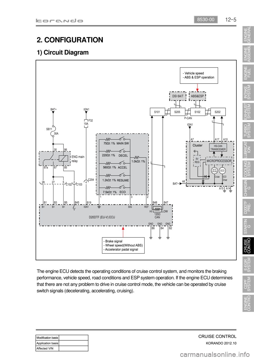
The engine ECU detects the operating conditions of cruise control system, and monitors the braking
performance, vehicle speed, road conditions and ESP system operation. If the engine ECU determines
that there are not any problem to drive in cruise control mode, the vehicle can be operated by cruise
switch signals (decelerating, accelerating, cruising).
Page 259 of 1082

12-12
6) Normal Cancellation of the Cruise Control
The cruise control system will be canceled when one or more items of the following conditions are
applied;
When the brake pedal is depressed.
When the cruising speed is downed less than 38 km/h.
When pushing the ON-OFF switch of the cruise control lever.
When ESP is activated.
When applying the parking brake when driving.
When using the clutch in order to shift (M/T only).
And the cruise control system can be operated again in driving state. 1.
2.
3.
4.
5.
Keep the main cruise control switch in the neutral position when not using the cruise control.
Page 261 of 1082

13-31793-01
E-EGR bypass valve Solenoid valve Drivien byVacuum
(Solenoid valve)
1. SPECIFICATION
Item
E-EGR valve Motor EGR response time 50 mS
Driven by DC motor
Valve EGR gas flow rate 120 Kg/h
Position sensor Sensing type Hall sensor
Supply voltage 5V ± 10%
Signal range 5% ~ 95%
Max. current consumption<15mA
E-EGR cooler Cooling capacity 8.3 kW or more
Coolin fin type Wavy fin
Coller type U-shaped