air condition SSANGYONG KORANDO 2012 Service Manual
[x] Cancel search | Manufacturer: SSANGYONG, Model Year: 2012, Model line: KORANDO, Model: SSANGYONG KORANDO 2012Pages: 1082, PDF Size: 96.1 MB
Page 104 of 1082
01-8
4) Basic Inspection
(1) Horn operation
Listen for the horn sound when pressing the horn pad on the steering wheel. -
(2) Brake operation
Check if there is any abnormal noise, unusually long braking distance, or uneven braking force. If the
brake warning lamp does not go out even after starting the engien or are flashing during driving,
have the brake system checked immediately.
Check the brake pipes and hoses for connection, oil leak, crack or interference after changing the
position of tires. When replacing the tires, check the brake disc for surface condition and wear.
Check the parking brake cable and brake operation. Shorten the checking interval if the parking
brake is used frequently. -
-
-
(3) Exhaust system
Be aware to any changes in sound or smell from the exhaust system. These may be caused by leak or
overheat. Have the exhaust system checked and repaired immediately.
Inspect the exhaust system including catalytic converter. Inspect all the components and body frame
near the exhaust system. -
-
(4) Tires
Unusual vibration of the steering wheel and seats or pulling to one side on the straight and level roads
may indicates the uneven tire inflation pressure or poor wheel balance. -
(5) Steering and suspension system
Inspect the front and rear suspension and the steering system for damage, looseness or missing
parts, signs of wear or lack of lubrication. Inspect the power steering line and the hoses for
connection, leak, crack and chafing. Inspect the drive axle boot and seals for damage, tear or leak.
Replace or repair the system if necessary. -
(6) Engine oil
Check the oil level when the engine is still warm and add the specified engine oil if necessary. -
(7) Coolant
Check the coolant level in the coolant reservoir, coolant conditions (contamination, foreign material),
and hoses for damage and leak. Replace or add the Ssangyong genuine coolant, if needed. -
(8) Engine drive belt
Check all drive belts on the engine for wear, crack and looseness. Retighten or replace the belt, if
needed. -
Page 163 of 1082
03-28
The engine ECU calculates the accelerator pedal based on the input signals from various sensors, and
controls the overall operation of the vehicle.
The ECU receives the signals from various sensor through data line, and performs effective air-fuel ratio
control based on these signals.
The crankshaft speed (position) sensor measures the engine speed, and the camshaft speed (position)
sensor determines the order of injections, and the ECU detects the amount of the accelerator pedal
depressed (driver's will) by receiving the electrical signals from the accelerator pedal sensor.
The mass air flow sensor detects the volume of intake air and sends the value to the ECU.
The major function of the ECU is controlling air-fuel ratio to reduce the emission level (EGR valve control)
by detecting instantaneous air flow change with the signals from the mass air flow sensor.
Also, the ECU uses the signals from the coolant temperature & air temperature sensors, booster pressure
sensor, atmospheric pressure sensor to: a) determine injection starting point and set value for pilot
injection, and b) deal with various operations and variable conditions.
Page 166 of 1082
04-30000-00
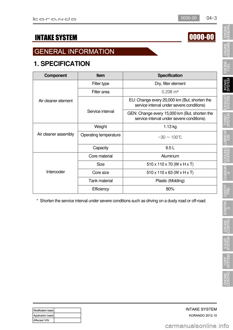
1. SPECIFICATION
Component Item Specification
Air cleaner elementFilter type Dry, filter element
Filter area0.208 m²
Service intervalEU: Change every 20,000 km (But, shorten the
service interval under severe conditions)
GEN: Change every 15,000 km (But, shorten the
service interval under severe conditions)
Air cleaner assemblyWeight 1.13 kg
Operating temperature
-30 ~ 100℃
Capacity 6.5 L
IntercoolerCore material Aluminum
Size 510 x 110 x 70 (W x H x T)
Core size 510 x 110 x 63 (W x H x T)
Tank material Plastic (Molding)
Efficiency 80%
Shorten the service interval under severe conditions such as driving on a dusty road or off-road. *
Page 174 of 1082

04-110000-00
Load Engine speed Swirl
valveAmount of
swirlRemarks
Low speed,
Low loadbelow 3,000 rpm Closed HeavyIncreased EGR ratio, better air-fuel
mixture (reduce exhaust gas)
High speed,
High loadover 3,000 rpm Open LightIncrease charge efficiency, higher
engine power
The variable swirl valve actuator operates when
turning the ignition switch ON/OFF position to
open/close the swirl valve. In this period, the soot
will be removed and the learning for swirl valve
position is performed.
Swirl valve
Swirl: This is the twisted (radial) air flow along the cylinder wall during the intake stroke. This
stabilizes the combustion even in lean air-fuel mixture condition.
3) Features
Swirl and air intake efficiency
To generate the swirl, the intake port should be serpentine design. This makes the resistance in air
flow. The resistance in air flow in engine high speed decreases the intake efficiency. Eventually, the
engine power is also decreased, Thus, the swirl operation is deactivated in high speed range to
increase the intake efficiency.
Relationship between swirl and EGR
To reduce Nox, it is essential to increase EGR ratio. However, if EGR ratio is too high, the PM also
could be very higher. And, the exhaust gas should be evenly mixed with newly aspired air. Otherwise,
PM and CO are dramatically increased in highly concentrated exhaust gas range and EGR ratio
could not be increased beyond a certain limit. If the swirl valve operates in this moment, the limit of
EGR ratio will be higher. -
-
4) Relationship between swirl and fuel injection pressure
The injector for DI engine uses the multi hole design. For this vehicle, there are 8 holes in injector. If the
swirl is too strong, the injection angles might be overlapped and may cause the increased PM and
insufficient engine power. Also, if the injection pressure is too high during strong swirl, the injection angles
might be overlapped. Therefore, the system may decreases the fuel injection pressure when the swirl is
too strong.
Page 183 of 1082
06-6
3) Inspection of Turbine
Thoroughly check the followings.
Interference: In case where is trace of interference or smallest damage on the compressor wheel
means, most of times, that abrasion has occurred on the journal bearing. Must inspect after the
overhaul.
Oil Leakage: The reason for oil leakage at the compressor section is the air cleaner, clogged by
substances such as dust, causes the compressor inlet negative pressure. -
-
Rotating in high speed at no-load for extended period of time can cause oil leakage to the
compressor section as oil pressure within the center housing gets higher than pressure within the
compressor housing.
Overuse of engine break (especially in low gear) in down hill makes significantly low exhaust gas
energy compared to the time where great amount of air is required during idling conditions of the
engine. Therefore, amount of air in the compressor inlet increases but the turbocharge pressure
is not high, which makes negative pressure at the compressor section causing the oilleakage
within the center housing. a.
b.
No problem will occur with the turbocharger if above conditions are found in early stage but oil
leaked over long period of time will solidify at each section causing to breakout secondary
defects.
Damages by foreign materials: In case where the compressor wheel is damaged by foreign materials
requires having an overhaul. At this time, it's necessary to check whether the foreign materials have
contaminated intake/exhaust manifold or inside of engine.
Must absolutely not operate the turbocharger with the compressor outlet and inlet opened
as it could damage the turbocharger or be hazardous during inspection.
Page 188 of 1082
06-110000-00
3. TROUBLESHOOTING
The followings are cautions to take in handling defects of turbocharger, which must be fully aware of.
1) Cautions
After stopping the engine, check whether the bolts on pipe connecting section are
loose as well as the connecting condition of vacuum port and modulator, which is
connected to the actuator.
During idling of the engine, check for leakage in the connecting section of pipe (hoses
and pipes, duct connections, after the turbocharger) by applying soap water. The
leakage condition in the engine block and turbine housing opening can be determined
by the occurrence of abnormal noise of exhaust.
By running the engine at idle speed, abnormal vibration and noise can be checked.
Immediately stop the engine when abnormal vibration and noise is detected and make
thorough inspection whether the turbocharger shaft wheel has any damages as well as
checking the condition of connections between pipes.
In case where the noise of engine is louder than usual, there is possibility of dampness
in the areas related with air cleaner and engine or engine block and turbocharger. And
it could affect the smooth supply of engine oil and discharge.
Check for damp condition in exhaust gas when there is sign of thermal discoloration or
discharge of carbon in connecting area of the duct.
When the engine rotates or in case where there is change in noise level, check for
clogging of air cleaner or air cleaner duct or if there is any significant amount of dust in
the compressor housing.
During the inspection of center housing, inspect inside of the housing by removing the
oil drain pipe to check for sludge generation and its attachment condition at shaft area
or turbine side.
Inspect or replace the air cleaner when the compressor wheel is damaged by inflow of
foreign materials.
Inspect both side of the turbocharger wheel after removing inlet and outlet pipe of the
turbocharger.
- Is the rotation smooth when the rotor is rotated by hand?
- Is the movement of bearing normal?
- Inspect whether there has been any signs of interference between two wheels. 1.
2.
3.
4.
5.
6.
7.
8.
9.
It's important not to drive the engine when the intake manifold hose has been removed.
Page 198 of 1082

06-210000-00
Basic principle at low speed
At low speed, it utilizes the principle of venturi. For
example, when air flows through the venturi tube,
the flow speed is faster and the pressure is lower
at the point "A". In this case, if the inner diameter
of venturi is more narrowed, the flow speed is so
much faster (refer to the equation). ※
Control
rangeTurbocharger driving
mechanismControl method
EffectImproved
performance
At low
speedNarrows the flow
passage for the
exhaust gas by
folding the vanesThe flow rate is
increased as the
exhaust gas passes
the narrow passage
→ Increased
turbine & impeller
speed, Increased
compressive forceImproved
low speed torque
4. OPERATING PRINCIPLES
The E-VGT is designed to get more improved engine power in all ranges by controlling the turbine as
follows:
1) How it Works at Low Speed
Normal turbocharger cannot get the turbo effect because the amount of exhaust gas is not enough and
the flow speed is slow in a low speed zone, but VGT allows the flow passage of exhaust to narrow,
resulting in increasing the flow speed of exhaust gas and running the turbine quickly and powerfully.
Therefore, as VGT can intake more air than normal turbocharger, it can give the benefit of the increased
output even in a low speed zone.
Turbocharger lag
The turbocharger is at idle speed when there is no load or it is in the normal driving condition. During
this period, the amount of exhaust gas passing through the turbine is not enough to turn the
compressor wheel (impeller) fast. Therefore, the intake air is not compressed as needed.
Because of this, it takes time for turbocharger to supply the additional power after the accelerator
pedal is depressed. This is called "turbocharger lag".
Page 229 of 1082
10-51413-00
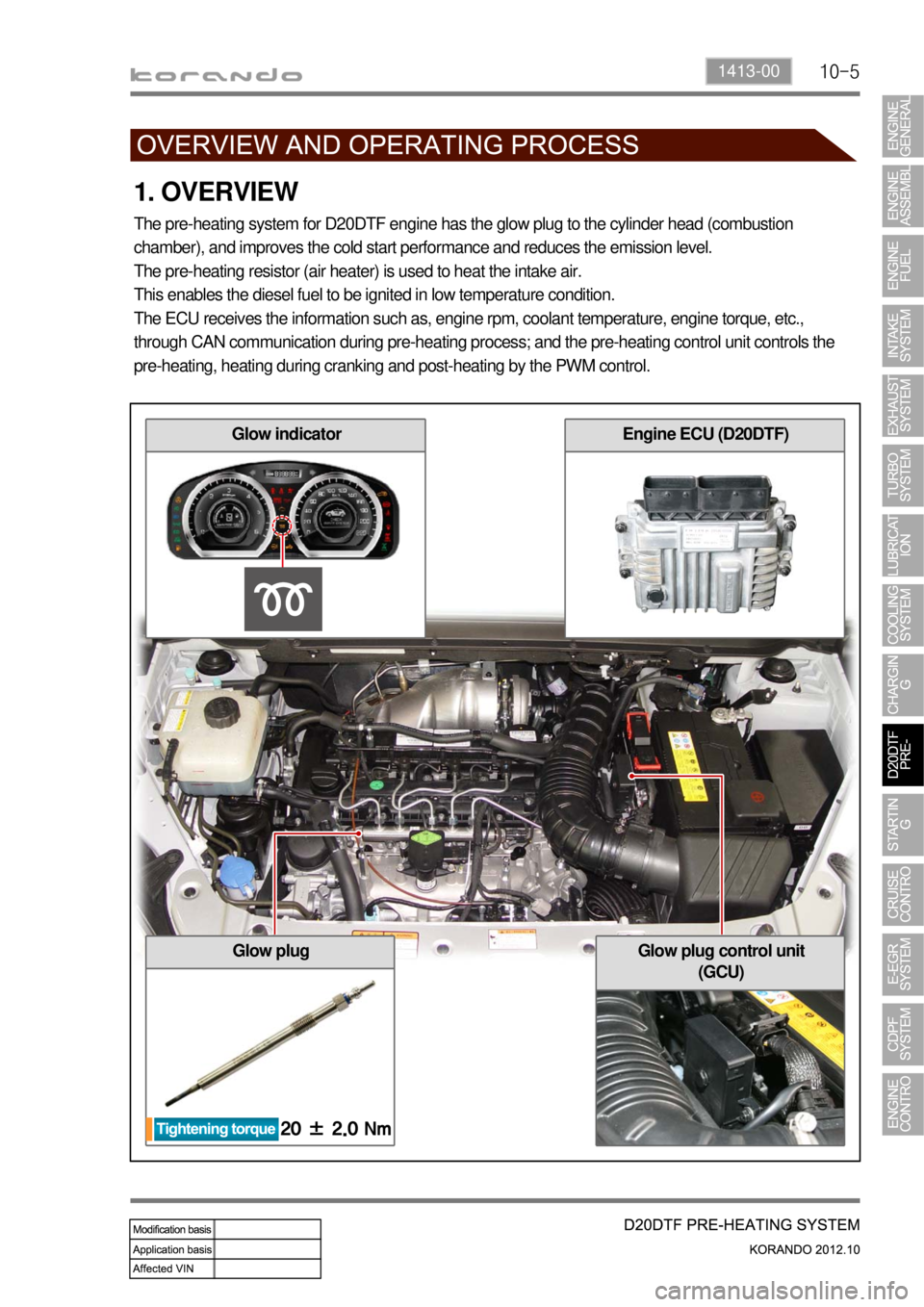
1. OVERVIEW
The pre-heating system for D20DTF engine has the glow plug to the cylinder head (combustion
chamber), and improves the cold start performance and reduces the emission level.
The pre-heating resistor (air heater) is used to heat the intake air.
This enables the diesel fuel to be ignited in low temperature condition.
The ECU receives the information such as, engine rpm, coolant temperature, engine torque, etc.,
through CAN communication during pre-heating process; and the pre-heating control unit controls the
pre-heating, heating during cranking and post-heating by the PWM control.
Glow plugGlow plug control unit
(GCU)
Glow indicatorEngine ECU (D20DTF)
Page 265 of 1082
13-71793-01
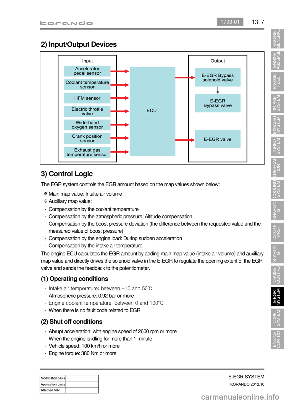
2) Input/Output Devices
3) Control Logic
The EGR system controls the EGR amount based on the map values shown below:
Main map value: Intake air volume
Auxiliary map value: ※
※
Compensation by the coolant temperature
Compensation by the atmospheric pressure: Altitude compensation
Compensation by the boost pressure deviation (the difference between the requested value and the
measured value of boost pressure)
Compensation by the engine load: During sudden acceleration
Compensation by the intake air temperature -
-
-
-
-
The engine ECU calculates the EGR amount by adding main map value (intake air volume) and auxiliary
map value and directly drives the solenoid valve in the E-EGR to regulate the opening extent of the EGR
valve and sends the feedback to the potentiometer.
(1) Operating conditions
Intake air temperature: between -10 and 50℃
Atmospheric pressure: 0.92 bar or more
Engine coolant temperature: between 0 and 100°C
When there is no fault code related to EGR -
-
-
-
(2) Shut off conditions
Abrupt acceleration: with engine speed of 2600 rpm or more
When the engine is idling for more than 1 minute
Vehicle speed: 100 km/h or more
Engine torque: 380 Nm or more -
-
-
-
Page 268 of 1082
14-51114-00
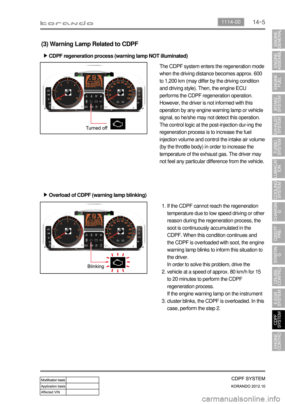
(3) Warning Lamp Related to CDPF
CDPF regeneration process (warning lamp NOT illuminated) ▶
Overload of CDPF (warning lamp blinking) ▶
The CDPF system enters the regeneration mode
when the driving distance becomes approx. 600
to 1,200 km (may differ by the driving condition
and driving style). Then, the engine ECU
performs the CDPF regeneration operation.
However, the driver is not informed with this
operation by any engine warning lamp or vehicle
signal, so he/she may not detect this operation.
The control logic at the post-injection dur-ing the
regeneration process is to increase the fuel
injection volume and control the intake air volume
(by the throttle body) in order to increase the
temperature of the exhaust gas. The driver may
not feel any particular difference from the vehicle.
If the CDPF cannot reach the regeneration
temperature due to low speed driving or other
reason during the regeneration process, the
soot is continuously accumulated in the
CDPF. When this condition continues and
the CDPF is overloaded with soot, the engine
warning lamp blinks to inform this situation to
the driver.
In order to solve this problem, drive the
vehicle at a speed of approx. 80 km/h for 15
to 20 minutes to perform the CDPF
regeneration process.
If the engine warning lamp on the instrument
cluster blinks, the CDPF is overloaded. In this
case, perform the step 2. 1.
2.
3.