warning SSANGYONG KORANDO 2013 Owners Manual
[x] Cancel search | Manufacturer: SSANGYONG, Model Year: 2013, Model line: KORANDO, Model: SSANGYONG KORANDO 2013Pages: 1336, PDF Size: 92.18 MB
Page 994 of 1336

A. Indicators on instrument cluster
C. HECU assembly
The HECU assemblies for ABS and ESP have
similar appearance but they have different inner
structure and connector connections from each
other. D. Front brake assembly
The disc brake for 4WD vehicle is the same with
the one for 2WD vehicle.
7. BRAKE SYSTEM AND ESP SYSTEM LAYOUT
B. Master cylinder assembly
Description for master cylinder in this chapter is
based on ABS/ESP equipped vehicle. For CBS,
there is an extra pressure valve mounted to the
master cylinder.
CaliperDisc
Parking brake
warning light
ABS warning lamp
ESP indicator
Page 1000 of 1336
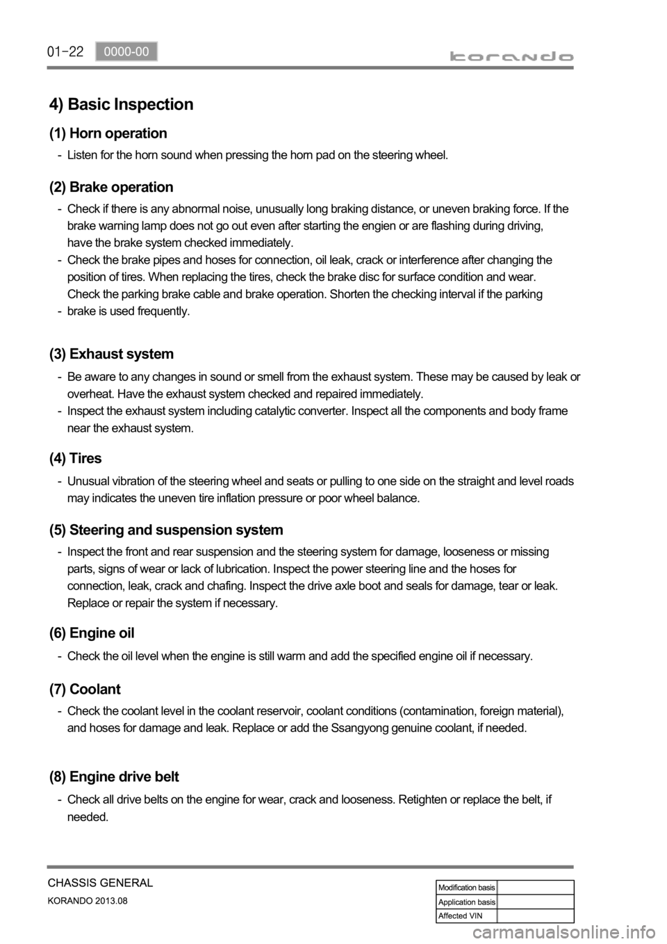
4) Basic Inspection
(1) Horn operation
Listen for the horn sound when pressing the horn pad on the steering wheel. -
(2) Brake operation
Check if there is any abnormal noise, unusually long braking distance, or uneven braking force. If the
brake warning lamp does not go out even after starting the engien or are flashing during driving,
have the brake system checked immediately.
Check the brake pipes and hoses for connection, oil leak, crack or interference after changing the
position of tires. When replacing the tires, check the brake disc for surface condition and wear.
Check the parking brake cable and brake operation. Shorten the checking interval if the parking
brake is used frequently. -
-
-
(3) Exhaust system
Be aware to any changes in sound or smell from the exhaust system. These may be caused by leak or
overheat. Have the exhaust system checked and repaired immediately.
Inspect the exhaust system including catalytic converter. Inspect all the components and body frame
near the exhaust system. -
-
(4) Tires
Unusual vibration of the steering wheel and seats or pulling to one side on the straight and level roads
may indicates the uneven tire inflation pressure or poor wheel balance. -
(5) Steering and suspension system
Inspect the front and rear suspension and the steering system for damage, looseness or missing
parts, signs of wear or lack of lubrication. Inspect the power steering line and the hoses for
connection, leak, crack and chafing. Inspect the drive axle boot and seals for damage, tear or leak.
Replace or repair the system if necessary. -
(6) Engine oil
Check the oil level when the engine is still warm and add the specified engine oil if necessary. -
(7) Coolant
Check the coolant level in the coolant reservoir, coolant conditions (contamination, foreign material),
and hoses for damage and leak. Replace or add the Ssangyong genuine coolant, if needed. -
(8) Engine drive belt
Check all drive belts on the engine for wear, crack and looseness. Retighten or replace the belt, if
needed. -
Page 1015 of 1336
3680-01
This information is used by the TCU to decide which shift pattern to select and for shift energy
management. Electro-hydraulic solenoid valves and variable bleed solenoids control the transaxle gear
changes.
Six variable bleed solenoids and four on/off solenoids are used to direct transaxle fluid flow to control the
fluid pressure within the three clutches and two bands. Separate pressure regulators are used
exclusively for torque converter clutch control and main transaxle line pressure.
The TCU monitors all TCU inputs and outputs to confirm correct system operation. If a fault occurs the
TCU is able to perform default action and inform the driver of the problem through the instrument cluster
warning lights. Detailed information is available via trouble codes which can be read with the service tool.
Page 1043 of 1336
3660-01
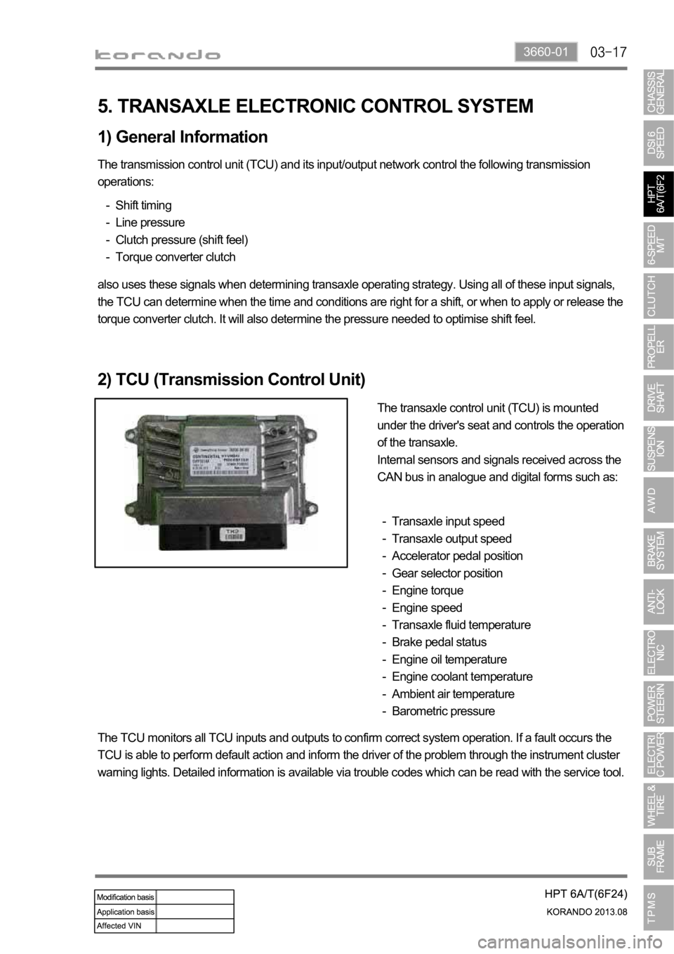
5. TRANSAXLE ELECTRONIC CONTROL SYSTEM
1) General Information
The transmission control unit (TCU) and its input/output network control the following transmission
operations:
Shift timing
Line pressure
Clutch pressure (shift feel)
Torque converter clutch -
-
-
-
also uses these signals when determining transaxle operating strategy. Using all of these input signals,
the TCU can determine when the time and conditions are right for a shift, or when to apply or release the
torque converter clutch. It will also determine the pressure needed to optimise shift feel.
2) TCU (Transmission Control Unit)
The transaxle control unit (TCU) is mounted
under the driver's seat and controls the operation
of the transaxle.
Internal sensors and signals received across the
CAN bus in analogue and digital forms such as:
Transaxle input speed
Transaxle output speed
Accelerator pedal position
Gear selector position
Engine torque
Engine speed
Transaxle fluid temperature
Brake pedal status
Engine oil temperature
Engine coolant temperature
Ambient air temperature
Barometric pressure -
-
-
-
-
-
-
-
-
-
-
-
The TCU monitors all TCU inputs and outputs to confirm correct system operation. If a fault occurs the
TCU is able to perform default action and inform the driver of the problem through the instrument cluster
warning lights. Detailed information is available via trouble codes which can be read with the service tool.
Page 1089 of 1336
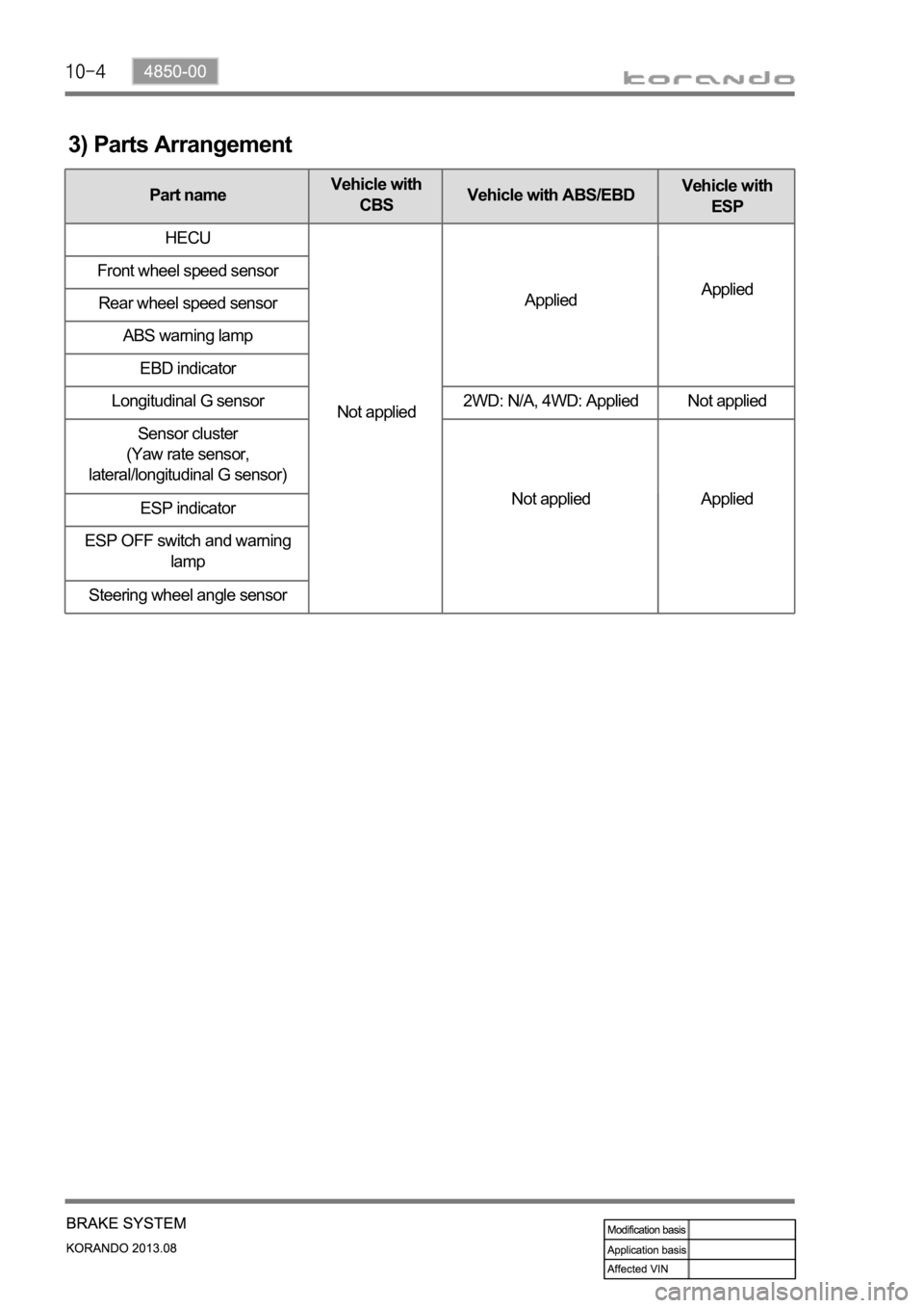
3) Parts Arrangement
Part nameVehicle with
CBSVehicle with ABS/EBDVehicle with
ESP
HECU
Not appliedAppliedApplied Front wheel speed sensor
Rear wheel speed sensor
ABS warning lamp
EBD indicator
Longitudinal G sensor 2WD: N/A, 4WD: Applied Not applied
Sensor cluster
(Yaw rate sensor,
lateral/longitudinal G sensor)
Not applied Applied
ESP indicator
ESP OFF switch and warning
lamp
Steering wheel angle sensor
Page 1090 of 1336

4850-00
A. Meter cluster-ABS, EBD, ESP
indicator/warning lampB. Master cylinder and
boosterC. HECU
F. Front/rear wheel speed sensor
Front/rear-4WD Rear-2WDH. Parking brakeG. Brake pedal
4) Component
ABS warning lamp
ESP indicator
D. Front brake
assembly
E. Rear brake
assembly
Disc
Disc
Parking brake
warning lamp
Caliper
Caliper
Page 1102 of 1336
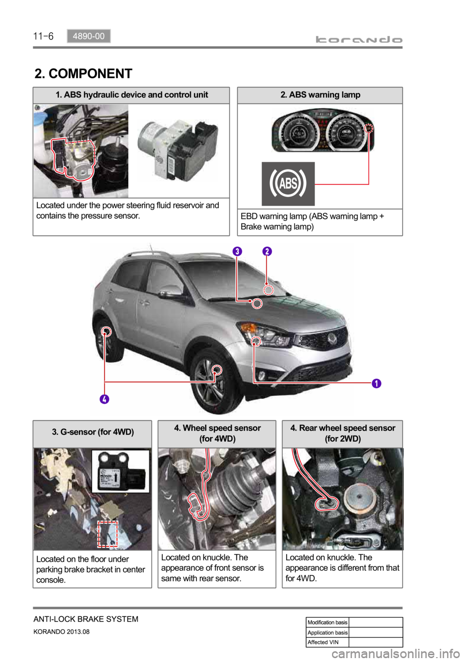
3. G-sensor (for 4WD)
Located on the floor under
parking brake bracket in center
console.4. Rear wheel speed sensor
(for 2WD)
Located on knuckle. The
appearance is different from that
for 4WD.4. Wheel speed sensor
(for 4WD)
Located on knuckle. The
appearance of front sensor is
same with rear sensor.
2. ABS warning lamp
EBD warning lamp (ABS warning lamp +
Brake warning lamp)1. ABS hydraulic device and control unit
Located under the power steering fluid reservoir and
contains the pressure sensor.
2. COMPONENT
Page 1106 of 1336

4. WARNING LAMPS
1) ABS Warning Lamp
ABS warning lamp module indicates the self diagnosis and malfunction.
ABS warning lamp ON:
When turning the ignition switch to ON position, ABS warning lamp comes on for 3 seconds for self-
diagnosis and goes off if the system is OK (initialization mode).
When the system is defective, the warning lamp comes on.
When the self-diagnosis is performing, the warning lamp comes on.
When the HECU connector is disconnected, the warning lamp comes on.
ABS is not available during lamp ON. In this condition, Only normal brake system without ABS function
is available.
When the communication between warning lamp CAN module in meter cluster, the warning lamp
comes on. 1.
2.
3.
4.
5.
6.
ABS warning lamp
Brake warning lamp
(EBD warning lamp: ABS warning lamp + Brake warning lamp) 1.
2.
Page 1107 of 1336

4890-00
2) EBD (Electronic Brake-force Distribution) Warning Lamp (Brake
Warning Lamp)
EBD warning lamp when the system performs the self diagnosis and when it detects the malfunction of
EBD system. However, the brake warning lamp comes on regardless of EBD when the parking brake is
applied.
EBD warning lamp ON:
When turning the ignition switch to ON position, ABS warning lamp and the brake warning lamp
comes on for 3 seconds for self diagnosis and goes off if the system is OK (initialization mode).
When applying the parking brake, the brake warning lamp comes on.
When the brake fluid is not sufficient, the brake warning lamp comes on.
When the self-diagnosis is performing, the warning lamp comes on.
When the HECU connector is disconnected, the warning lamp comes on.
When the system is defective, ABS warning lamp and the brake warning lamp come on
simultaneously. 1.
2.
3.
4.
5.
6.
When the solenoid valve is defective
When one or more wheel sensors are defective
When ABS HECU is defective
When the voltage is abnormal
When valve relay is defective a.
b.
c.
d.
e.
When the communication between warning lamp CAN module in meter cluster, the warning lamp
comes on. 7.
Page 1124 of 1336
0000-00
3. PRECAUTIONS
The warning lamp flashes and warning beep sounds when the ESP is operating
When the ESP operates during vehicle movement, the ESP warning lamp on the instrument panel
flashes and beep comes on every 0.1 second. The ESP system is only a supplementary device for
comfortable driving. When the vehicle exceeds its physical limits, it cannot be controlled.
Do not rely on the system. Keep on the safe driving.
Feeling when ESP is working
When the ESP system activates, the feeling can be different depending on vehicle driving conditions.
For example, you will feel differently when the ESP system is activated during the ABS is operating
with the brakes applied and when the brakes are not applied on a curve.
If the ESP system operates when the brake is applied, the brake pressure will be increased on the
corresponding wheel which already has braking pressure for the ESP controls.
ARP Operation
During the ARP operation, vehicle safety (rollover prevention) takes the first priority and thus,
stronger engine control is in effect. Consequently, the vehicle speed decreases rapidly, so the driver
must take caution for the vehicle may drift away from the lane.
Noise and vibration that driver feels when ESP system is operating
The ESP system may transfer noise and vibration to the driver due to the pressure changes caused
by the motor and valve operations in a very short period of time. And, keep in mind that the output
and vehicle speed could be decreased without rpm increase due to the ASR function that controls
the engine power.