warning SSANGYONG KORANDO 2013 Service Manual
[x] Cancel search | Manufacturer: SSANGYONG, Model Year: 2013, Model line: KORANDO, Model: SSANGYONG KORANDO 2013Pages: 1336, PDF Size: 92.18 MB
Page 1125 of 1336

4. WARNING LAMPS
1) ABS
ABS warning lamp module indicates the self-diagnosis and malfunction.
ABS warning lamp ON: Warning Lamp
When turning the ignition switch to ON position, ABS warning lamp comes on for 3 seconds for self-
diagnosis and goes off if the system is OK (initialization mode).
When the system is defective, the warning lamp comes on.
When the self-diagnosis is performing, the warning lamp comes on.
When the HECU connector is disconnected, the warning lamp comes on.
ABS is not available during lamp ON. In this condition, Only normal brake system without ABS
function is available.
When the communication between warning lamp CAN module in meter cluster, the warning lamp
comes on. 1.
2.
3.
4.
5.
6.ABS warning lamp
Brake warning lamp
ESP OFF indicator
ESP warning lamp/indicator
EBD warning lamp 1.
2.
3.
4.
5.
Page 1126 of 1336

0000-00
2) EBD (Electronic Brake-force Distribution) Warning Lamp (Brake
Warning Lamp)
EBD warning lamp when the system perform the self diagnosis and when it detects the malfunction of
EBD system. However, the brake warning lamp comes on regardless of EBD when the parking brake is
applied.
EBD warning lamp ON:
When turning the ignition switch to ON position, ABS warning lamp and the brake warning lamp
comes on for 3 seconds for self diagnosis and goes off if the system is OK (initialization mode).
When applying the parking brake, the brake warning lamp comes on.
When the brake fluid is not sufficient, the brake warning lamp comes on.
When the self-diagnosis is performing, the warning lamp comes on.
When the HECU connector is disconnected, the warning lamp comes on.
When the system is defective, ABS warning lamp and the brake warning lamp come on
simultaneously. 1.
2.
3.
4.
5.
6.
When the solenoid valve is defective
When one or more wheel sensors are defective
When ABS HECU is defective
When the voltage is abnormal
When valve relay is defective a.
b.
c.
d.
e.
When the communication between warning lamp CAN module in meter cluster, the warning lamp
comes on. 7.
3) ESP OFF Indicator
ESP OFF indicator ON:
When turning the ignition switch to ON position, ESP warning lamp comes on for 3 seconds for self
diagnosis and goes off if the system is OK (initialization mode).
When the ESP OFF switch is pressed to turn off ESP function, ESP OFF indicator comes on. 1.
2.
4) ESP Warning Lamp
ESP warning lamp ON:
When turning the ignition switch to ON position, ESP warning lamp comes on for 3 seconds for self
diagnosis and goes off if the system is OK (initialization mode).
When the system is defective, the warning lamp comes on.
When the ESP function is activated, ESP warning lamp blinks with the interval of 2 Hz.
When the communication between warning lamp CAN module in meter cluster, the warning lamp
comes on. 1.
2.
3.
4.
5.
5) ESP OFF Switch
If ESP OFF switch is pressed, ESP function is deactivated and the ESP OFF indicator in the instrument
cluster comes on.
To resume the ESP function, press the switch again. At this time, ESP OFF indicator goes out.
Page 1134 of 1336

0000-00
7) Emergency Hazard Flasher Control (Coupled with ABS)
(1) System layout
(2) Emergency stop signal function
When ABS system is operating (or sudden braking), the hazard warning flashers will blink for 10
seconds to inform the emergency situation to the vehicles behind.
(3) Operating process
When receiving the emergency stop signal through PCAN communication it blinks with the interval of 4
Hz and when receiving the emergency stop OFF signal through PCAN communication it blinks with the
interval of 1.25 Hz, normal operating speed.
However, the manual operation of the switch has a priority over this function.
flasher
Page 1137 of 1336

Circuit description
When compared to the vehicle equipped with ABS/EBD only, the internal hydraulic circuit has a
normally-open separation valve and a shuttle valve in primary circuit and in secondary circuit.
When the vehicle brakes are not applied during engine running or when applying the non-ABS operating
brakes, the normally-open separation valve and the inlet valve are open, whereas the normally-closed
shuttle valve and the outlet valve are closed.
When the ESP system is operating, the normally-open separation valve will be closed by the solenoid
valve operation and the hydraulic circuit will be established by the shuttle valve. Then, the inlet and outlet
valves will be closed or open depending on the braking pressure RISE, HOLD or DUMP conditions.
Flashing warning lamp and warning sound during ESP operation
When the ESP operates while the vehicle is moving, the ESP warning lamp on the instrument panel
flickers and the buzzer sounds at every 0.1 second. The ESP lamp operation is to inform a driver that the
vehicle is extremely unstable.
The ESP system is just a supplementary system for the vehicle and it cannot control the vehicle over the
physical limit. Do not solely rely on the system but be advised to drive the vehicle safely.
Drive feeling during ESP operation
When the ESP system activates, the driving feeling can be different depending on vehicle driving
conditions. For example, it will feel different when the ESP system is activated while the ABS is operated
by depressing the brake pedal and when the ESP system is in control without the brake pedal
depressed on the same curve.
If the ESP system operates with the brake applied, the brake pressure will be increased on the
corresponding wheel which already has braking pressure for the ESP controls. In other words, the ESP
system would make the driver feel more abruptly braked compared to the situation that the braking
pressure is applied to wheel which had no braking force.
Noise and vibration that driver senses during ESP operation
The ESP system may transfer noise and vibration to a driver due to the pressure changes caused by the
motor and valve operations in a very short period of time.
Extreme cornering will trigger the ESP operation and this will make the driver sense noise and vibration
due to sudden brake application.
Also, the ESP system controls the engine power. Therefore, the driver may notice the engine power
decreases even when the accelerator pedal is depressed.
Page 1143 of 1336

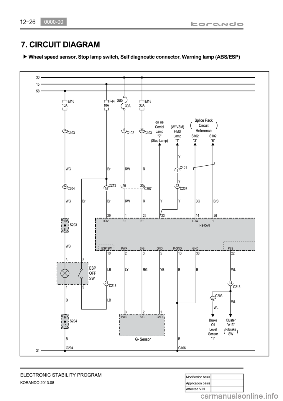
7. CIRCUIT DIAGRAM
Wheel speed sensor, Stop lamp switch, Self diagnostic connector, Warning lamp (ABS/ESP)
Page 1172 of 1336

4190-00
3. CAUTIONS
The tire pressure values displayed on the instrument cluster are sent from the wheel modules after
the vehicle is driven for a period of time. Therefore, they are not displayed at initial start (more than
20 minutes have elapsed after ignition off). It can be displayed after 10 minutes of driving at speed of
20 km/h or higher. -
The TPMS uses a radio frequency and a high frequency band between the wheel module and the
TPMS ECU for communication.
Therefore, if the vehicle is equipped with the electronic equipment such as mobile camera monitor
or the vehicle is passing through the area with a strong electromagnetic field, the system may not
operate normally.
For the vehicle equipped with the TPMS, the TPMS warning lamp on the instrument cluster comes
on and pressure values on the EL display is displayed as bars (--) after driving for a certain period of
time if a newly installed tire is not equipped with the wheel module. -
-
At initial startDisplay pressure value after
detecting
position automatically
Standard type
Supervision type
Page 1175 of 1336

Instrument cluster display related to TPMS (with standard)
DOT LCD display TPMS warning lamp Global warning lamp
2. LAYOUT 1. OVERVIEW
The TPMS is used to reduce the accident rate, enhance driving stability and avoid an unnecessary fuel
consumption and tire wear by monitoring the tire pressure and temperature to inform the driver of tire
pressure information and its status through the instrument cluster. The wheel module fitted in the tire
transmits the internal data for the tire to the TPMS ECU periodically through the wireless transmission.
The TPMS ECU can detect the positions of the wheel modules fitted to each wheel automatically and
sends the signal on tire condition through the CAN line to the instrument cluster so that the driver can
identify the wheel module in question.
Instrument cluster display related to TPMS (with supervision)
DOT LCD display TPMS warning lamp Global warning lamp
Page 1178 of 1336

4190-00
4. TPMS PRESSURE VALUE DISPLAYING PROCESS
The TPMS ECU receives the tire pressure value from the wheel module through the wireless
transmission once every about 30 seconds and displays the pressure value on the instrument cluster
through CAN line.
Under normal circumstances, it transmits the tire pressure value and temperature value together
with its ID (Identification) once every about 30 seconds to reduce the load on the wheel module's
battery. But, in the event of emergency or situation which should give a warning to the driver, it
transmits the data once every about 1 second. Since the battery consumption will be increased
rapidly until the data transmission interval will be returned to normal after certain length of time,
adjust the tire pressure to the specified one after rectifying the cause.
The tire pressure is displayed through the following sequences, which occur at the same
time.
Wheel module detection
(Auto learning)This is a step which receives an ID signal from the wheel module fitted
to the vehicle. When the wheel module sends the signal about twice
every 1 minute, each wheel module will be identified.
Wheel module mounting
location detection
(Auto location)The TPMS ECU check which wheel module is installed to which tire.
Page 1179 of 1336

5. LOW TIRE PRESSURE WARNING
If the tire pressure is less than 13% of the proper value calculated by the TPMS ECU depending on the
ambient temperature for more than 8 minutes, the 1st low tire pressure warning is given. And, if the tire
pressure is less than 20% for more than 4 minutes, the 2nd warning is given. At this time, the "Check
tire" message is displayed on the DOT LCD display and the global warning lamp comes on.
ECU receives the ambient temperature signal from the instrument cluster through CAN
communication and calculates the proper tire pressure to correct it since the tire pressure changes
depending on the ambient temperature.
Page 1181 of 1336

Display on cluster
TPMS warning lamp
Global warning lamp
DOT LCD display
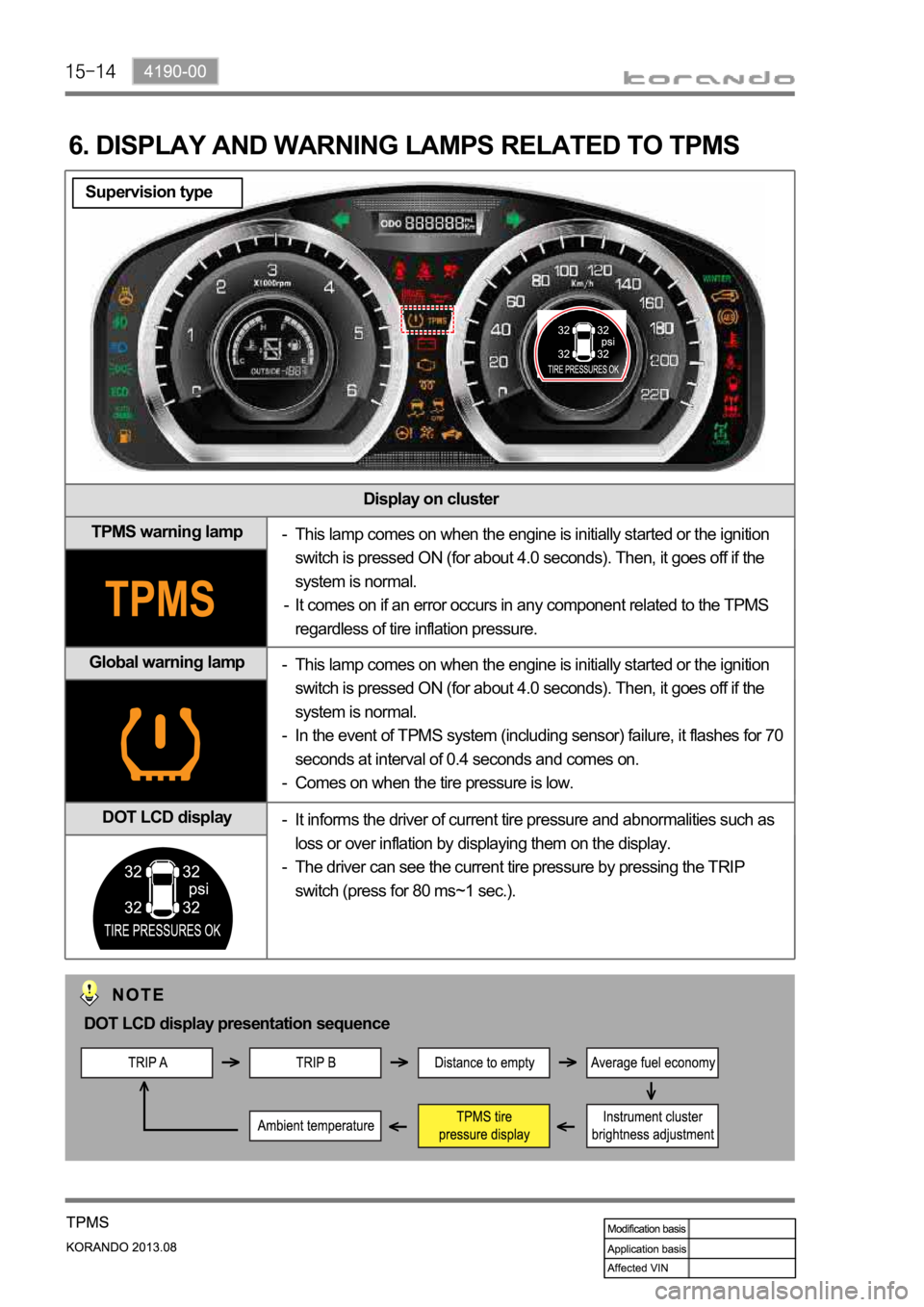
6. DISPLAY AND WARNING LAMPS RELATED TO TPMS
This lamp comes on when the engine is initially started or the ignition
switch is pressed ON (for about 4.0 seconds). Then, it goes off if the
system is normal.
It comes on if an error occurs in any component related to the TPMS
regardless of tire inflation pressure. -
-
This lamp comes on when the engine is initially started or the ignition
switch is pressed ON (for about 4.0 seconds). Then, it goes off if the
system is normal.
In the event of TPMS system (including sensor) failure, it flashes for 70
seconds at interval of 0.4 seconds and comes on.
Comes on when the tire pressure is low. -
-
-
It informs the driver of current tire pressure and abnormalities such as
loss or over inflation by displaying them on the display.
The driver can see the current tire pressure by pressing the TRIP
switch (press for 80 ms~1 sec.). -
-
DOT LCD display presentation sequence
Supervision type